1
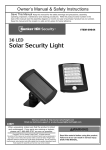
Owner’s Manual & Safety Instructions
Save This Manual Keep this manual for the safety warnings and precautions, assembly, operating,
inspection, maintenance and cleaning procedures. Write the product’s serial number in the back of the manual
near the assembly diagram (or month and year of purchase if product has no number). Keep this manual and
the receipt in a safe and dry place for future reference.
ITEM 69643
Visit our website at: http://www.harborfreight.com
Email our technical support at: [email protected]
When unpacking, make sure that the product is intact
and undamaged. If any parts are missing or broken,
please call 1-800-444-3353 as soon as possible.
Copyright© 2012 by Harbor Freight Tools®. All rights reserved.
No portion of this manual or any artwork contained herein may be reproduced in
any shape or form without the express written consent of Harbor Freight Tools.
Diagrams within this manual may not be drawn proportionally. Due to continuing
improvements, actual product may differ slightly from the product described herein.
Tools required for assembly and service may not be included.
Read this material before using this product.
Failure to do so can result in serious injury.
Save this manual.
Table of Contents
Safety
Safety.......................................................... 2
Maintenance................................................ 9
Specifications.............................................. 4
Setup........................................................... 4
Operation..................................................... 6
Parts List and Diagram............................... 10
Warranty..................................................... 12
WARNING SYMBOLS AND DEFINITIONS
Setup
This is the safety alert symbol. It is used to alert you to potential personal injury hazards.
Obey all safety messages that follow this symbol to avoid possible injury or death.
Indicates a hazardous situation which, if not avoided,
will result in death or serious injury.
Indicates a hazardous situation which, if not avoided,
could result in death or serious injury.
Indicates a hazardous situation which, if not avoided,
could result in minor or moderate injury.
Addresses practices not related to personal injury.
Operation
Important Safety Information
Read all safety warnings and instructions.
Failure to follow the warnings and instructions may result in electric shock, fire and/or serious injury.
Save all warnings and instructions for future reference.
1. Keep installation area clean. Cluttered
areas invite accidents.
Maintenance
2. Observe installation area conditions. Keep
work area well lit during installation.
3. Check for damaged parts. Before using
any product, any part that appears damaged
should be carefully checked to determine that
it will operate properly and perform its intended
function. Check for any broken or damaged
parts and any other conditions that may affect its
operation. Replace or repair damaged or worn
parts immediately. Do not use the Security Light
if any switch does not turn on and off properly.
Page 2
4. Replacement parts and accessories. When
servicing, use only identical replacement parts.
Use of any other parts will void the warranty.
5. Check hardware and assembled parts
after assembling. All connections should
be tight and hardware tightened.
6. Keep children away. Mount the Light, Solar
Panel, and Cord out of children’s reach.
For technical questions, please call 1-800-444-3353.
Item 69643
9. Maintain products with care. Keep the Solar
Powered Security Light clean for better and safer
performance. Inspect the Light periodically. If
damaged, have it repaired by a qualified technician.
10. Do not overreach. Keep proper footing and
balance at all times. If a ladder is to be used during
installation, it should be supported by an assistant.
11. Do not set up the Solar Powered Security Light
if under the influence of alcohol or drugs. Read
warning labels on prescriptions to determine if your
judgement or reflexes are impaired while taking
drugs. If there is any doubt, do not set up the Light.
13. Have your power tool serviced by a
qualified repair person using only identical
replacement parts. This will ensure that the
safety of the power tool is maintained.
14. WARNING: Handling the cord on this product’s
Charger will expose you to lead, a chemical
known to the State of California to cause cancer,
and birth defects or other reproductive harm.
Wash hands after handling.
(California Health & Safety Code § 25249.5, et seq.)
15. The warnings, precautions, and instructions
discussed in this instruction manual cannot
cover all possible conditions and situations
that may occur. It must be understood by the
operator that common sense and caution are
factors which cannot be built into this product,
but must be supplied by the operator.
Maintenance
Operation
Save these instructions.
Safety
8. Use eye protection. Wear ANSI-approved impact
safety goggles when setting up this product.
12. NiCd BATTERY MUST BE RECYCLED
OR DISPOSED OF PROPERLY. Do not
short, incinerate or open battery.
Setup
7. Dress properly. Protective, electrically nonconductive clothes and nonskid footwear are
recommended when working with the Solar
Powered Security Light. Wear restrictive
hair covering to contain long hair.
Item 69643
For technical questions, please call 1-800-444-3353.
Page 3
Specifications
Safety
Lamp
60 Super Bright White LEDs
Battery Pack
6V, 900mAh, NiCd Battery Pack
Solar Panel
6-1/4" x 5" Amorphous Solar Panel
Detects Motion
Up to 50'
Range of Motion
Up to 120°
Delay Time
5 to 120 Seconds (adjustable)
Setup - Before Use:
Read the entire Important Safety Information section at the beginning of this
manual including all text under subheadings therein before set up or use of this product.
Note: For additional information regarding the parts listed in the following pages,
refer to Parts List and Diagram on page 10.
Setup
Installation
1. Decide where you want to place the Lamp and the
Solar Panel. The Solar Panel is equipped with
a 16 ft. connecting wire, so the Lamp and Solar
Panel can be installed up to 16 ft. apart. The Solar
Panel must be set in a location that receives
full, direct sunlight, a minimum of eight hours
a day. Ideally, the solar panel should be angled
slightly toward the south (northern hemisphere).
2. Mount the Solar Panel:
Operation
a. Place the Solar Panel in the desired location,
adjusting the unit to best fit the surface.
b. Mark the hole locations of the Base,
then set the Solar Panel aside.
3. Mount the Lamp:
a. Locate the unit six to eight feet above ground
on a solid surface capable of supporting the
Lamp and secure enough so that it will not
move when exposed to vibrations or wind.
The unit must be high enough to allow for
motion detection and light distribution.
b. Mark the hole locations of the Mounting
Bracket, then set the Lamp aside.
c. Check that the marked areas are clear of
obstacles such as cables and electrical
lines. Drill holes for the enclosed Screws.
d. Secure the Lamp in place with the screws.
c. Check that the marked areas are clear of
obstacles such as cables and electrical
lines. Drill holes for the enclosed
Screws and plastic Anchors.
4. Carefully route the Power Cord of the Solar Panel
to the Lamp and plug it into the Battery Housing
Outlet on the back of the Battery Housing.
d. Insert the plastic Anchors then secure the
Solar Panel in place with the screws.
5. Loosen the Detector Angle Lock, swivel
the Motion Detector Head so that it faces
the area where movement will occur, and
tighten the Detector Angle Lock.
Maintenance
Page 4
For technical questions, please call 1-800-444-3353.
Item 69643
Functions
Lamp
Solar Panel
Safety
Mounting Bracket
Battery Housing
Power Switch
(On bottom of
Battery Housing)
Base
Detector Angle Lock
(On side of Motion
Detector Head)
Motion Detector Head
Setup
Battery Housing Outlet
(On bottom of Battery Housing)
Solar Panel Cable
Motion Detector Controls
(On bottom of
Motion Detector Head)
Maintenance
Operation
Figure A
Item 69643
For technical questions, please call 1-800-444-3353.
Page 5
Operating Instructions
Read the entire Important Safety Information section at the beginning of this
manual including all text under subheadings therein before set up or use of this product.
Safety
Initial Battery Charging
Before the Security Light can operate
properly, the batteries need to be fully
charged. To charge the batteries:
1. Turn OFF the Power Switch.
2. ALLOW 3 DAYS OF FULL SUNLIGHT
to fully charge the batteries.
3. After charging, turn the Power Switch Auto. The light
will illuminate for a short time when first switched
on. This indicates that it is working properly.
CAUTION
The UNIT WILL NOT FUNCTION
UNLESS:
The Solar Panel is first charged for
3 DAYS OF FULL SUN
with the SENSOR POWER OFF.
Setup
Power Switch
The Power Switch, located under the Battery
Housing of the Lamp has three settings:
ON: Towards the Lamp. The lamp stays
on functioning as a normal light.
OFF: Center position.
AUTO: Away from the Lamp. The light
will turn on automatically when motion is
detected by the Motion Sensor Head.
Motion Detector Control Knobs
Operation
The Solar Powered Security Light has 3
different Control Knobs on the underside of the
Motion Detector Head. They control the Motion
Detector Head’s sensor. They are sensitivity
to light (LUX), the light’s duration (TIME) and
the sensor’s sensitivity to motion (SENS).
NOTE: After each adjustment, walk the detection
area to check the adjustment just made.
SENS
Adjusting
Knob
TIME Adjusting Knob
SENS TIME
LUX
LUX
Adjusting
Knob
Underside of Motion
Detector Head
Maintenance
Page 6
For technical questions, please call 1-800-444-3353.
Item 69643
Motion Detector Control Knobs (cont.)
LUX (Light Level)
Adjust Light Level
(When light will go ON).
The LUX Adjusting Knob (9) tells the
sensor the level of darkness that must be
reached before the Light turns on.
Minimum Position
Turning the dial counterclockwise
to the minimum setting lowers the
sensor level. The sensor will only
trigger the light to turn on at dusk
or when it is dark out. This is the
ideal position for general evening
and night operation.
Safety
LUX
Maximum Position
Turning the dial clockwise to the
maximum setting increases the
sensor level. The light will go on
in most situations ranging from
dark to daylight.
Setup
Note: If the Security Light is not operating at night due to interference from a street light or other
interference, turn the LUX knob towards the maximum setting ( ). Adjust the dial as needed
between the minimum and maximum settings to achieve the desired level of sensitivity.
TIME (Light Duration)
2
min
Adjust Time
5
(How long light stays ON).
sec
The TIME Adjusting Knob (11) sets how
long the Light stays lit after motion is
no longer detected by the sensor.
Mid Range
Adjusting the dial between the
Minimum and Maximum to
choose any time between 5
seconds and 2 minutes for the
light to stay on after motion is no
longer detected.
Maximum Position
Turn the dial clockwise to the
maximum for the light to stay on
for 2 minutes after motion is no
longer detected.
Maintenance
The TIME is adjustable from 5 seconds to 2 minutes.
Minimum Position
Turn the dial counterclockwise to
the minimum for the light to stay
on for 5 seconds after motion is
no longer detected.
Operation
TIME
Item 69643
For technical questions, please call 1-800-444-3353.
Page 7
Motion Detector Control Knobs (cont.)
SENS (Sensitivity)
Safety
SENS
Adjust Sensitivity
(To sense small or large
moving objects).
The SENS Adjusting Knob (10) sets the level of
sensitivity of the Motion Detector Head.
Setup
The Motion Detector Head is most sensitive to
movement across the detection zone, rather than
movement toward or away from the
Motion Detector Head (6).
Movement is best detected at a distance of
40 feet or less.
Sensitivity is affected by the ambient air temperature.
If it is hot outside, the sensor has difficulty detecting
changes in heat. In cold temperatures, the sensitivity
is increased and may need to be adjusted.
Minimum Position
Turn the dial counterclockwise
to the minimum setting. Ideal
for cold winter conditions or
when nuisance tripping is a
problem. If the light is activated
by small animals or rapid
changes in heat, the sensitivity can be reduced by
turning the knob counterclockwise towards the
minimum setting (“-”).
Maximum Position
Turn the dial clockwise to the
maximum setting. Ideal for hot
summer conditions or to
maximize range.
Note: Turn the dial anywhere between the minimum and
maximum settings to adjust the level of sensitivity, as needed.
Testing the Light
Operation
After the battery is charged and the control Knobs are set, walk slowly around the detection area. The sensor
detects infrared radiation given off by a person or animal. This triggers the Light to turn on. The Light should go
on in the area that you set up the Security Light to monitor. Adjust the Knobs and sensor and re-test until the unit
functions as desired. Repeat the test procedure as needed when there are weather and/or temperature changes.
Maintenance
Page 8
For technical questions, please call 1-800-444-3353.
Item 69643
Maintenance and Servicing
Safety
Procedures not specifically explained in this manual must
be performed only by a qualified technician.
To prevent SERIOUS injury from TOOL FAILURE:
Do not use damaged equipment. If abnormal noise or vibration
occurs, have the problem corrected before further use.
Cleaning, Maintenance, and Lubrication
2. After Use, wipe external surfaces
of the tool with clean cloth.
3. NiCd BATTERY MUST BE RECYCLED
OR DISPOSED OF PROPERLY. Do not
short, incinerate or open battery.
Setup
1. BEFORE EACH USE, inspect the general
condition of the tool. Check for:
• leaking, swollen, or cracked battery pack,
• loose hardware,
• misalignment or binding of parts,
• cracked or broken parts, and
• any other condition that may
affect its safe operation.
Troubleshooting
Light turns on
LUX control is set too close to .
during day.
Light flashes
Low battery.
on and off with
clicking sounds.
Light stays
1. Duration time setting too long.
“ON”.
2. Frequent changes in heat being
detected.
Light turns ON
and OFF.
3. Power Switch set to ON.
1. Changes in heat are being
detected from a fixed heat
source or moving object.
2. Sudden temperature change
due to storms or high winds.
Likely Solutions
1. Check that Power Switch is set to ON or AUTO.
2. Plug in firmly at back of Battery Housing.
3. Turn LUX knob towards .
4. Adjust angle and direction of Motion Detector Head.
5. Keep solar panel clean. Allow to charge in full
sunlight for 3 days with the Power Switch OFF.
Turn knob towards
.
With Switch set to “OFF”, allow to charge in full
sunlight for 3 days before further use.
1. Turn TIME knob counterclockwise to
reduce the time the light stays on.
2. Check sensing area for possible heat sources such
as air vents, vehicles or objects in wind. Reposition
the Motion Detector Head if needed, or turn SENS
Knob counterclockwise to lower sensitivity.
3. Turn Power Switch to AUTO.
1. Check sensing area for possible heat sources
such as air vents, vehicles or objects in wind.
Reposition the Motion Detector Head.
2. Turn Power Switch “OFF” until storm passes.
Mount in a sheltered location.
Follow all safety precautions whenever diagnosing or servicing the tool.
Disconnect Battery Pack and Charger power supply before service.
Item 69643
Operation
Possible Causes
1. Power is not on.
2. Cable connection is loose.
3. LUX control is set
too close to .
4. Motion sensor not
detecting movement.
5. Battery pack not fully charged.
For technical questions, please call 1-800-444-3353.
Page 9
Maintenance
Problem
Light won’t
turn on.
Parts List and Diagram
PLEASE READ THE FOLLOWING CAREFULLY
Safety
The manufacturer and/or distributor has provided the parts list and assembly diagram
in this manual as a reference tool only. Neither the manufacturer or distributor
makes any representation or warranty of any kind to the buyer that he or she is
qualified to make any repairs to the product, or that he or she is qualified to replace
any parts of the product. In fact, the manufacturer and/or distributor expressly
states that all repairs and parts replacements should be undertaken by certified and
licensed technicians, and not by the buyer. The buyer assumes all risk and liability
arising out of his or her repairs to the original product or replacement parts
thereto, or arising out of his or her installation of replacement parts thereto.
Parts List
Part
Setup
1
2
3
4
5
6
7
Description
Lamp
Solar Panel
Mounting Screw
LED
Battery Housing
Motion Detector Head
Mounting Plate
Qty
1
1
6
60
1
1
1
Part
8
9
10
11
12
13
14
Description
Power Switch
Battery Housing Outlet
Solar Panel Mounting Bracket
LUX Adjusting Knob
SENS Adjusting Knob
TIME Adjusting Knob
6V NiCd Battery Pack (not shown)
Qty
1
1
1
1
1
1
1
Operation
Maintenance
Record Product’s Serial Number Here:
Note: If product has no serial number, record month and year of purchase instead.
Note: Some parts are listed and shown for illustration purposes only,
and are not available individually as replacement parts.
Page 10
For technical questions, please call 1-800-444-3353.
Item 69643
Operation
Setup
Safety
Assembly Diagram
13
12
SENS TIME
LUX
11
Item 69643
For technical questions, please call 1-800-444-3353.
Maintenance
Underside of Motion
Detector Head (6)
Page 11
Limited 90 Day Warranty
Harbor Freight Tools Co. makes every effort to assure that its products meet high quality and durability standards,
and warrants to the original purchaser that this product is free from defects in materials and workmanship for the
period of 90 days from the date of purchase. This warranty does not apply to damage due directly or indirectly,
to misuse, abuse, negligence or accidents, repairs or alterations outside our facilities, criminal activity, improper
installation, normal wear and tear, or to lack of maintenance. We shall in no event be liable for death, injuries
to persons or property, or for incidental, contingent, special or consequential damages arising from the use of
our product. Some states do not allow the exclusion or limitation of incidental or consequential damages, so the
above limitation of exclusion may not apply to you. This warranty is expressly in lieu of all other
warranties, express or implied, including the warranties of merchantability and fitness.
To take advantage of this warranty, the product or part must be returned to us with transportation charges
prepaid. Proof of purchase date and an explanation of the complaint must accompany the merchandise.
If our inspection verifies the defect, we will either repair or replace the product at our election or we may
elect to refund the purchase price if we cannot readily and quickly provide you with a replacement. We will
return repaired products at our expense, but if we determine there is no defect, or that the defect resulted
from causes not within the scope of our warranty, then you must bear the cost of returning the product.
This warranty gives you specific legal rights and you may also have other rights which vary from state to state.
3491 Mission Oaks Blvd. • PO Box 6009 • Camarillo, CA 93011 • (800) 444-3353