1
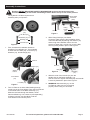
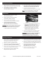
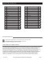
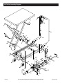
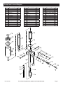
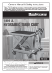
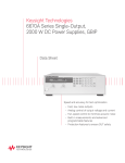
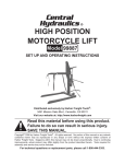
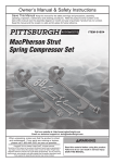
Specifications
Capacity
Table Height
Table Size
500 lb.
9" – 28-1/2"
27-3/8" x 17-3/4"
Unpacking Precautions
Note: When unpacking, use assistance when lifting the Hydraulic Lift Table from the box.
Or set the packaging box sideways and slide the Lift Table out from the box sideways.
CAUTION! When lifting Hydraulic Lift Table from packaging box, be sure to grip the main frame.
Do not just grip the Table. Doing so will only raise up the Table and keep the unit’s frame in the packaging box.
Important Safety Information
1. Do not exceed 500 lb. max weight capacity.
Be aware of dynamic loading!
Sudden load movement may briefly create
excess load causing product failure.
2. Use only on flat, level and hard surface capable of
supporting the Lift Table and any item(s) placed on
Table. Evenly distribute load on Table to avoid tipping.
3. Use as intended only. Do not use Lift Table to
lift or transport animals, pets, or people.
4. Assemble only according to these instructions.
Improper assembly can create hazards.
5. Follow all hydraulic bleeding instructions
specified in this manual.
6. Wear ANSI-approved safety goggles and heavy-duty
work gloves during assembly and use.
Page 2
7. Keep assembly area clean and well lit.
8. Keep bystanders out of the area during assembly.
9. Do not assemble when tired or when under
the influence of drugs or medication.
10. This product is not a toy. Do not allow
children to play with or near this item.
11. Use as intended only.
12. Inspect before every use; do not use
if parts are loose or damaged.
13. Maintain product labels and nameplates.
These carry important safety information.
If unreadable or missing, contact
Harbor Freight Tools for a replacement.
For technical questions, please call 1-800-444-3353.
Item 60730
Assembly Instructions
Read the ENTIRE IMPORTANT SAFETY INFORMATION section at the beginning of this
document including all text under subheadings therein before set up or use of this product.
The Hydraulic Lift Table requires some
assembly after you unpack it.
Front
Wheels
(47)
Wrench
Lifting
Pedal
(27)
Bolt (29)
Figure 3
Lock Nuts (14)
Washer (15)
Bushing (48)
Hex Bolts (16)
Figure 1
Lifting Pedal
Connector
(30a)
1. First, set aside the hardware needed to
install the Front Wheels (47). The hardware
includes the Hex Bolts (16), Lock Nuts (14),
Washers (15), and Bushings (48).
3. Slide Lifting Pedal (27) into Pedal
Connector (30a), aligning the installation holes.
Then slide the Bolt (29) through the Washer (15)
and through the installation holes. Use the
wrench to fasten the Lock Nut (12) over the Bolt,
securing Lifting Pedal in place. See Figure 3.
Handle
(21)
Wrench
Washer (15)
Bolt (20)
Wheel
Frame
Figure 4
Lock Nut (14)
2. Turn Lift Table on its side. Slide Bushing through
center hole in the Front Wheel. Then set Front Wheel
in the wheel frame of the Base Assembly (17).
Slide the Hex Bolt through the Washer, wheel
frame and Bushing. Use a wrench (sold separately)
to fasten Lock Nut onto Hex Bolts, until the
Front Wheel is secured into place.
Item 60730
Base
Assembly
(17)
4. Slide the ends of the Handle (21) into the
handle slots on the Base Assembly (17).
Use the wrench to tighten the Bolts (20) until Handle
is securely fastened in place. See Figure 4.
Front Wheel
(47)
Figure 2
Wrench
5. WARNING! After assembly, try out the
Lift Table to make sure it is functioning
properly before using it to lift a load.
For technical questions, please call 1-800-444-3353.
Page 3
Operating Instructions
1. Before loading and while stationary, lock the back
Casters (19) to prevent the Lift Table from moving.
2. The Lift Table (1) is raised by pumping
the Lifting Pedal (27) with your foot until
the desired height is achieved.
3. Once desired height is reached, swing down the
Safety Bars (7) on either side of the Lift Frame.
This helps prevent uncontrolled Lift Table drop.
4. To lower the Lift Table, Squeeze the
Release Handle (22) at the top of the main Handle.
Note: Be sure to lift Safety Bars up, allowing the
Lift Table to be completely lowered (if needed).
Maintenance
1. Lubricate hydraulic connections monthly
with a good quality grease.
Hex Bolt
(16)
Control
Cable
(49)
2. Check for the free movement and wear
of the wheels. Replace if needed.
Cable Bolt (50)
3. Check the Caster brakes regularly.
They should lock firmly and release completely.
4. If you encounter difficulty using the
Release Handle to lower the Lift Table,
the Control Cable (49) may need adjusting.
WARNING! Make sure the Release Handle is pressed
only halfway down during adjustment. This will allow
the Lift Table to lower slowly for safety purposes.
a. With assistance, tip over Table Cart.
Figure 5
b. Loosen the Cable Bolt (50) and Cable Nut (51)
and tug the Control Cable until it is tight.
WARNING! Do not pull too tight; you want to
leave a small amount of give. See Figure 5.
c. Re-fasten the Nut and Bolt. Then test the
Release Handle, making sure the Release
Handle is pressed halfway down.
5. Check for oil leakage from the hydraulic cylinder.
The hydraulic cylinder is not user serviceable.
WARNING! Any service or repairs to the Hydraulic
Lift Table should be performed by a qualified
service technician. Improper repairs or service
could result in equipment failure or personal injury.
Bleeding Instructions
If the Lift Table is not performing properly, it may
be due to air in the hydraulic system. Follow
these steps to bleed air from the system.
1. Raise the Lift Table to its highest position.
2. Swing down the two Safety Bars so that they both
rest on the top platform of the Base Assembly.
3. Remove the rubber Oil Plug (J04). You can carefully
remove it with a large flat head screwdriver.
4. After the Oil Plug is removed, swing the two
Safety Bars back against their stops.
Page 4
5. Squeeze the Release Handle to lower the Lift Table.
This should purge the air out of the hydraulic system.
6. Raise the Lift Table to its highest position and swing
both Safety Bars down onto the Base Assembly (17).
7. Top off hydraulic fluid into the oil hole
where the Oil Plug goes until it is full.
Note: Make sure you use new oil.
8. Replace the Oil Plug by firmly pressing
it into the oil hole while twisting it.
For technical questions, please call 1-800-444-3353.
Item 60730
Hydraulic Table Cart Parts List
Part
1
2
3
4
5
6
7
8
9
10
11
12
13
14
15
16
17
18
19
20
21
22
23
24
25
26
Description
Lift Table
Lift Frame
Shaft
Retaining Ring
Pin (1)
Bolt
Safety Bar
Nut
Pin
Pin (2)
Pin (3)
Nut M8
Lock Washer
Lock Nut
Washer
Hex Bolt M8 x 60
Base Ass'y
Bolt M8 x 16
Caster Ass'y
Bolt M8 x 30
Handle
Release Handle
Bolt M8 x 25
Pin
Bolt Sleeve
Brake Thread
Qty
1
1
2
8
2
2
2
2
2
1
2
12
8
2
14
2
1
8
2
2
1
1
2
1
1
1
Part
27
28
29
30a
31
33a
34a
35
36
37
38
39
40
41
42a
44
45
46a
47
48
49
50
51
52
53
Description
Lifting Pedal
Bumper
Bolt
Lifting Pedal Connector
Pin (4)
Connecting Plate
Cotter
Pin (5)
Pin (6)
Retaining Ring
Spring Cap
Spring
Spring
Bolt
Release Valve Link
R-pin
Pin (7)
Pump
Front Wheel
Wheel Bushing (not shown)
Control Cable (not shown)
Cable Bolt (not shown)
Cable Nut (not shown)
Washer
Retaining Ring
Qty
1
1
1
1
1
1
2
1
1
2
1
1
1
1
1
1
1
1
2
2
1
1
1
1
1
Record Serial Number Here:
Note:
If product has no serial number, record month and year of purchase instead.
Note: Some parts are listed and shown for illustration purposes only,
and are not available individually as replacement parts.
PLEASE READ THE FOLLOWING CAREFULLY
THE MANUFACTURER AND/OR DISTRIBUTOR HAS PROVIDED THE PARTS LIST AND ASSEMBLY DIAGRAM
IN THIS DOCUMENT AS A REFERENCE TOOL ONLY. NEITHER THE MANUFACTURER OR DISTRIBUTOR
MAKES ANY REPRESENTATION OR WARRANTY OF ANY KIND TO THE BUYER THAT HE OR SHE IS
QUALIFIED TO MAKE ANY REPAIRS TO THE PRODUCT, OR THAT HE OR SHE IS QUALIFIED TO REPLACE
ANY PARTS OF THE PRODUCT. IN FACT, THE MANUFACTURER AND/OR DISTRIBUTOR EXPRESSLY
STATES THAT ALL REPAIRS AND PARTS REPLACEMENTS SHOULD BE UNDERTAKEN BY CERTIFIED AND
LICENSED TECHNICIANS, AND NOT BY THE BUYER. THE BUYER ASSUMES ALL RISK AND LIABILITY
ARISING OUT OF HIS OR HER REPAIRS TO THE ORIGINAL PRODUCT OR REPLACEMENT PARTS
THERETO, OR ARISING OUT OF HIS OR HER INSTALLATION OF REPLACEMENT PARTS THERETO.
Item 60730
For technical questions, please call 1-800-444-3353.
Page 5
Lift Table Assembly Diagram
53
30a
33a
52
34a
34a
46a
Page 6
42a
For technical questions, please call 1-800-444-3353.
Item 60730
Pump Parts List and Diagram
Part Description
J01
J02
J03
J04
J05
J06
J07
J08
J09
J10
J11
J12
J13
J14
J15
Qty
O-ring
Top Nut
Nylon Ring
Oil Plug
Reservoir
Ram
Cup Seal
O-ring
Screw
Packing Washer
Spring
Ball
Oil Filter
Cylinder
Washer
Part Description
1
1
1
1
1
1
1
1
2
2
1
2
1
1
1
J16
J17
J18
J19
J20
J21
J22
J23
J24
J25
J26
J27
J28
J29
J30
Qty
Nylon Ring
Oil Filter
Spring
Ball
Ball Cup
Spring
Screw
O-ring
Screw
Plastic Cap
Spring Collar
Oil Filter
Valve Plug
Spring
Ball
Part Description
1
1
1
1
1
1
1
1
1
1
2
1
1
1
1
J31
J32
J33
J34
J35
J36
J37
J38
J39
J40
J41
J42
J43
J44
O-ring
Seal Ring
O-ring
Damp Valve Seat
Spring
O-ring
Damp Valve Rod
Screw
Pump
Copper Washer
Pump Cylinder
Seal Ring
Seal Ring
Pump Piston
Qty
1
1
1
1
1
1
1
1
1
1
1
1
1
1
J
J
J
J
J
J
J
J
J
J
J
J
J
J
J
J
J
J
J
J
J
J
J
J
J
J
J
J
J
J
J
J
J
J
J
J
J
J
J
J
J
J
J
J
J
Item 60730
J
J
J
For technical questions, please call 1-800-444-3353.
Page 7
Limited 90 Day Warranty
Harbor Freight Tools Co. makes every effort to assure that its products meet high quality and durability standards,
and warrants to the original purchaser that this product is free from defects in materials and workmanship for the
period of 90 days from the date of purchase. This warranty does not apply to damage due directly or indirectly,
to misuse, abuse, negligence or accidents, repairs or alterations outside our facilities, criminal activity, improper
installation, normal wear and tear, or to lack of maintenance. We shall in no event be liable for death, injuries
to persons or property, or for incidental, contingent, special or consequential damages arising from the use of
our product. Some states do not allow the exclusion or limitation of incidental or consequential damages, so the
above limitation of exclusion may not apply to you. THIS WARRANTY IS EXPRESSLY IN LIEU OF ALL OTHER
WARRANTIES, EXPRESS OR IMPLIED, INCLUDING THE WARRANTIES OF MERCHANTABILITY AND FITNESS.
To take advantage of this warranty, the product or part must be returned to us with transportation charges
prepaid. Proof of purchase date and an explanation of the complaint must accompany the merchandise.
If our inspection verifies the defect, we will either repair or replace the product at our election or we may
elect to refund the purchase price if we cannot readily and quickly provide you with a replacement. We will
return repaired products at our expense, but if we determine there is no defect, or that the defect resulted
from causes not within the scope of our warranty, then you must bear the cost of returning the product.
This warranty gives you specific legal rights and you may also have other rights which vary from state to state.
3491 Mission Oaks Blvd. • PO Box 6009 • Camarillo, CA 93011 • (800) 444-3353