1
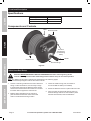
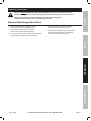
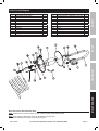
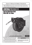
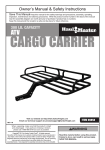
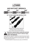
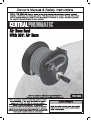
WARNING SYMBOLS AND DEFINITIONS
This is the safety alert symbol. It is used to alert you to potential personal injury hazards.
Obey all safety messages that follow this symbol to avoid possible injury or death.
SAFETY
Indicates a hazardous situation which, if not avoided,
will result in death or serious injury.
Indicates a hazardous situation which, if not avoided,
could result in death or serious injury.
Indicates a hazardous situation which, if not avoided,
could result in minor or moderate injury.
Addresses practices not related to personal injury.
IMPORTANT SAFETY INSTRUCTIONS
SETUP
INSTRUCTIONS PERTAINING TO A RISK OF INJURY TO PERSONS
WARNING – When using hose reels, basic precautions should always be followed, including the following:
To reduce the risk of injury to persons, read all the instructions before using the tool.
Work Area
1. Keep the work area clean and well lighted.
2. Keep bystanders, children, and visitors
away while operating the tool.
OPERATION
Personal Safety
1. Stay alert. Watch what you are doing and
use common sense when operating the tool.
Do not use the tool while tired or under the
influence of drugs, alcohol, or medication.
A moment of inattention while operating the
tool increases the risk of injury to persons.
2. Dress properly. Do not wear loose
clothing or jewelry. Contain long hair.
Keep hair, clothing, and gloves away from
moving parts. Loose clothes, jewelry, or long
hair increases the risk of injury to persons as
a result of being caught in moving parts.
3. Do not overreach.
Keep proper footing and balance at all times.
Proper footing and balance enables better
control of the tool in unexpected situations.
4.
Use safety equipment.
A dust mask, non-skid safety shoes and
a hard hat must be used for the
applicable conditions.
5.
Always wear eye protection.
Wear ANSI-approved safety goggles.
MAINTENANCE
Tool Use and Care
1. Do not force the tool. Use the correct tool for the
application. The correct tool will do the job better
and safer at the rate for which the tool is designed.
3. Store the tool when it is idle out of reach
of children and other untrained persons.
A tool is dangerous in the hands of untrained users.
2. Disconnect the tool from the air source
before making any adjustments, changing
accessories, or storing the tool. Such
preventive safety measures reduce the
risk of starting the tool unintentionally.
Page 2
For technical questions, please call 1-800-444-3353.
Item 69232
4. Check for misalignment or binding of moving
parts, breakage of parts, and any other condition
that affects the tool's operation. If damaged,
have the tool serviced before using. Many accidents
are caused by poorly maintained hose reels.
There is a risk of bursting if the tool is damaged.
5. Use only accessories that are identified by the
manufacturer for the specific tool model. Use of
an accessory not intended for use with the specific
tool model, increases the risk of injury to persons.
Service
1. Tool service must be performed only
by qualified repair personnel.
SAFETY
Tool Use and Care (cont.)
3. Use only the lubricants supplied with the
tool or specified by the manufacturer.
2. When servicing a tool, use only identical
replacement parts. Use only authorized parts.
1.
Never connect to an air source that is
capable of exceeding 200 psi.
Over pressurizing the tool may cause
bursting, abnormal operation, breakage
of the tool or serious injury to persons.
Use only clean, dry, regulated compressed air at the
rated pressure or within the rated pressure range as
marked on the tool. Always verify prior to using the
tool that the air source has been adjusted to the rated
air pressure or within the rated air-pressure range.
2. Never use oxygen, carbon dioxide, combustible
gases or any bottled gas as an air source
for the tool. Such gases are capable of
explosion and serious injury to persons.
SETUP
Air Source
Safety Symbol Definitions
Property or statement
PSI
Pounds per square inch of pressure
NPT
National pipe thread, tapered
WARNING marking
concerning Risk of Eye Injury.
Wear ANSI‑approved eye protection.
Symbol
Property or statement
WARNING marking concerning
Risk of Respiratory Injury. Wear
NIOSH‑approved dust mask/respirator.
WARNING marking concerning
Risk of Explosion.
OPERATION
Symbol
Specific Safety Instructions
2. Obey the manual for the air tool and air
compressor used with this tool.
3. Install an in-line shutoff valve to allow
immediate control over the air supply in an
emergency, even if a hose is ruptured.
4. WARNING: The brass components of
this product contain lead, a chemical
known to the State of California to cause
birth defects (or other reproductive harm).
(California Health & Safety code § 25249.5, et seq.)
SAVE THESE INSTRUCTIONS.
Item 69232
For technical questions, please call 1-800-444-3353.
Page 3
MAINTENANCE
1. The warnings and precautions discussed in this
manual cannot cover all possible conditions and
situations that may occur. It must be understood
by the operator that common sense and caution
are factors which cannot be built into this
product, but must be supplied by the operator.
Functional Description
Specifications
SAFETY
Hose Length
30'
Maximum Air Pressure
250 PSI
Air Inlet
1/4″ -18 NPT
Components and Controls
Hose
Mounting Plate
SETUP
Inlet from
Compressor
(on Mounting
Plate)
Handle
Outlet to tool
Reel Flange
OPERATION
Figure A
Initial Hose Reel Setup
Read the ENTIRE IMPORTANT SAFETY INFORMATION section at the beginning of this
manual including all text under subheadings therein before set up or use of this product.
Note: For additional information regarding the parts listed in the following pages,
refer to the Assembly Diagram near the end of this manual.
MAINTENANCE
1. Choose a mounting location that is free of electrical
wiring or other obstructions, and is sturdy enough
to support the weight of the Reel and hose as well
as the force used to extend and retract it. Purchase
four bolts able to support the same forces.
2. Make a paper template from the mounting
plate of the Reel. Mark the center of the bolt
holes in the desired mounting location.
Page 4
3. Check for hidden wiring, then, drill holes to
accommodate the bolts (not included).
4. Mount the Reel and secure in place with four bolts.
5. Align the holes of the Handle with the holes on
the Reel Flange and secure the Handle in place
with the three Screws, Nuts and Washers.
For technical questions, please call 1-800-444-3353.
Item 69232
Operating Instructions
Read the ENTIRE IMPORTANT SAFETY INFORMATION section at the beginning of this
manual including all text under subheadings therein before set up or use of this product.
SAFETY
Inspect tool before use, looking for damaged, loose, and missing parts.
If any problems are found, do not use tool until repaired.
General Operating Instructions
1. Attach a coupler (sold separately) to your
air compressor hose and apply thread
seal tape to the Inlet fitting on the Reel.
Connect the coupler to the Inlet fitting.
4. When finished using the Hose, disconnect
the air tool and wind the hose. Wipe the
Hose Reel clean with a dry cloth.
MAINTENANCE
OPERATION
SETUP
2. Connect your air tool to the other end of the Hose
using another coupler and thread seal tape.
3. Follow all instructions from the air tool
and compressor for set up and use.
Item 69232
For technical questions, please call 1-800-444-3353.
Page 5
User‑Maintenance Instructions
Procedures not specifically explained in this manual must
be performed only by a qualified technician.
SAFETY
TO PREVENT SERIOUS INJURY:
Detach air supply from this product before performing any inspection, maintenance, or cleaning procedures.
TO PREVENT SERIOUS INJURY FROM TOOL FAILURE:
Do not use damaged equipment. If abnormal noise, vibration,
or leaking air occurs, have the problem corrected before further use.
Cleaning, Maintenance, and Lubrication
Note: These procedures are in addition to the regular checks and maintenance
explained as part of the regular operation of the Hose Reel.
SETUP
1. BEFORE EACH USE, inspect the general
condition of the tool. Check for:
2. AFTER EACH USE, re-wind the hose onto the reel
and wipe the Hose Reel clean with a dry cloth.
• loose hardware or housing,
• misalignment or binding of moving parts,
• cracked or broken parts, and
• any other condition that may
affect its safe operation.
OPERATION
MAINTENANCE
Page 6
For technical questions, please call 1-800-444-3353.
Item 69232
Parts List and Diagram
Description
Base(welded with stand)
Stand
Fixed washer(welded on stand)
Washer
Position sleeve
Flange A
Sleeve
Flange B
Position sleeve
Washer
Spring
Washer
Qty
1
1
1
1
1
1
1
1
1
1
1
1
Part
13
14
15
16
17
18
19
20
21
22
23
24
Description
Swivel (including 2 valves & 2 O-rings)
Spring washer
Nut
Washer
Protector(rubber)
Clamp
Screw
Screw
Washer
Nut
Handle
Valve
Qty
1
1
3
3
1
1
3
3
3
3
1
1
MAINTENANCE
OPERATION
SETUP
1
2
3
4
5
6
7
8
9
10
11
12
SAFETY
Part
Record Product's Serial Number Here:
Note: If product has no serial number, record month and year of purchase instead.
Note: Some parts are listed and shown for illustration purposes only,
and are not available individually as replacement parts.
Item 69232
For technical questions, please call 1-800-444-3353.
Page 7
Limited 90 Day Warranty
Harbor Freight Tools Co. makes every effort to assure that its products meet high quality and durability standards,
and warrants to the original purchaser that this product is free from defects in materials and workmanship for the
period of 90 days from the date of purchase. This warranty does not apply to damage due directly or indirectly,
to misuse, abuse, negligence or accidents, repairs or alterations outside our facilities, criminal activity, improper
installation, normal wear and tear, or to lack of maintenance. We shall in no event be liable for death, injuries
to persons or property, or for incidental, contingent, special or consequential damages arising from the use of
our product. Some states do not allow the exclusion or limitation of incidental or consequential damages, so the
above limitation of exclusion may not apply to you. THIS WARRANTY IS EXPRESSLY IN LIEU OF ALL OTHER
WARRANTIES, EXPRESS OR IMPLIED, INCLUDING THE WARRANTIES OF MERCHANTABILITY AND FITNESS.
To take advantage of this warranty, the product or part must be returned to us with transportation charges
prepaid. Proof of purchase date and an explanation of the complaint must accompany the merchandise.
If our inspection verifies the defect, we will either repair or replace the product at our election or we may
elect to refund the purchase price if we cannot readily and quickly provide you with a replacement. We will
return repaired products at our expense, but if we determine there is no defect, or that the defect resulted
from causes not within the scope of our warranty, then you must bear the cost of returning the product.
This warranty gives you specific legal rights and you may also have other rights which vary from state to state.
PLEASE READ THE FOLLOWING CAREFULLY
THE MANUFACTURER AND/OR DISTRIBUTOR HAS PROVIDED THE PARTS LIST AND ASSEMBLY DIAGRAM
IN THIS MANUAL AS A REFERENCE TOOL ONLY. NEITHER THE MANUFACTURER OR DISTRIBUTOR
MAKES ANY REPRESENTATION OR WARRANTY OF ANY KIND TO THE BUYER THAT HE OR SHE IS
QUALIFIED TO MAKE ANY REPAIRS TO THE PRODUCT, OR THAT HE OR SHE IS QUALIFIED TO REPLACE
ANY PARTS OF THE PRODUCT. IN FACT, THE MANUFACTURER AND/OR DISTRIBUTOR EXPRESSLY
STATES THAT ALL REPAIRS AND PARTS REPLACEMENTS SHOULD BE UNDERTAKEN BY CERTIFIED AND
LICENSED TECHNICIANS, AND NOT BY THE BUYER. THE BUYER ASSUMES ALL RISK AND LIABILITY
ARISING OUT OF HIS OR HER REPAIRS TO THE ORIGINAL PRODUCT OR REPLACEMENT PARTS
THERETO, OR ARISING OUT OF HIS OR HER INSTALLATION OF REPLACEMENT PARTS THERETO.
3491 Mission Oaks Blvd. • PO Box 6009 • Camarillo, CA 93011 • (800) 444-3353