1
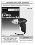
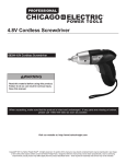
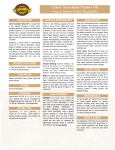
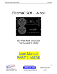
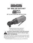
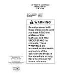
WARNING SYMBOLS AND DEFINITIONS
This is the safety alert symbol. It is used to alert you to potential personal injury hazards.
Obey all safety messages that follow this symbol to avoid possible injury or death.
Indicates a hazardous situation which, if not avoided,
will result in death or serious injury.
Indicates a hazardous situation which, if not avoided,
could result in death or serious injury.
Indicates a hazardous situation which, if not avoided,
could result in minor or moderate injury.
Addresses practices not related to personal injury.
IMPORTANT SAFETY INFORMATION
WARNING Read all safety warnings and instructions.
Failure to follow the warnings and instructions may result in serious injury.
Save all warnings and instructions for future reference.
1. Keep children and bystanders away
while operating. Distractions can
cause you to lose control.
2. Keep work area clean and well lit.
Cluttered or dark areas invite accidents.
3. Wear ANSI-approved safety goggles, NIOSHapproved dust mask/respirator, and heavyduty work gloves during use and service.
4. Stay alert and use common sense when
operating. Do not use when tired or under the
influence of drugs, alcohol or medication.
may affect the product’s operation. If damaged,
have the product repaired before use.
10. Use the product and accessories etc., in accordance
with these instructions and in the manner intended
for the particular type of product, taking into account
the working conditions and the work to be performed.
Use of the product for operations different from those
intended could result in a hazardous situation.
11. Have product serviced by a qualified repair person
using only identical replacement parts. This will
ensure that the safety of the product is maintained.
5. Do not overreach. Keep proper footing
and balance at all times. This enables
better control in unexpected situations.
12. Maintain labels and nameplates on the
product. These carry important safety
information. If unreadable or missing, contact
Harbor Freight Tools for a replacement.
6. Dress properly. Do not wear loose clothing or
jewelry. Keep your hair, clothing and gloves
away from moving parts. Loose clothes, jewelry
or long hair can be caught in moving parts.
13. This product contains or, when used, produces a
chemical known to the State of California to cause
cancer and birth defects or other reproductive harm.
(California Health & Safety Code § 25249.5, et seq.)
7. This product is not a toy. Keep it out
of reach of children.
14. Use caution when applying a load. Slowly and
carefully apply pressure to the vehicle part being
pressed. If the workpiece seems unusually hard
to press, immediately stop the operation. Carefully
disconnect the Ball Joint Kit from the workpiece, and
adjust the Ball Joint Kit to eliminate or diminish an
off-center load. Then, continue with the procedure.
8. Use the correct product for the correct
vehicle. The correct product will do the job
better and safer at the rate for which it was
designed. Do not modify this product or use
it for a purpose for which it is not intended.
9. Check for misalignment or binding of moving parts,
breakage of parts and any other condition that
Page 2
15. Do not use the Ball Joint Kit to compress
springs or any other item that could
disengage and cause a potential hazard.
For technical questions, please call 1-800-444-3353.
Item 4065
16. Do not allow any lubricants to make contact
between any part of the Ball Joint Kit and the
part being pressed. Lubricants of any type on
the above mentioned parts will diminish the
ability of the Ball Joint Kit to firmly and safely
grip and hold the Ball Joint Kit in position.
17. Examine the Ball Joint Kit for structural cracks,
bends, and any other condition that may affect
the safe operation of the tool. Do not use the
Ball Joint Kit even if minor damage appears.
18. Read and understand all instructions and safety
precautions as outlined in the manufacturer’s manual
for the vehicle you are servicing. Use the vehicle
manufacturer’s recommended ball joint press points.
19. The warnings, precautions, and instructions
discussed in this instruction manual cannot
cover all possible conditions and situations
that may occur. It must be understood by the
operator that common sense and caution are
factors which cannot be built into this product,
but must be supplied by the operator.
SAVE THESE INSTRUCTIONS.
Operating Instructions
Read the ENTIRE WARNING section at the beginning of this manual including all text under
subheadings therein before set up or use of this product.
Note: Read vehicle service manual to determine how to prepare the ball
joint for removal from a specific vehicle make/model.
To Remove a Ball Joint
1. Assemble the Ball Joint Press (1) over the
vehicle’s control arm. Select the correct
size Receiving Tube (3, 4, or 5), and
position it under the vehicle’s ball joint.
2. Place the Remove Adapter (7) between the
Receiving Tube and the Jackscrew (2). Then, place
the Install Adapter (6) between the top of the ball
joint and the Ball Joint Press. See Figure 1, below.
3. Tighten the Jackscrew until the Receiving
Tube contacts the vehicle’s control arm.
4. Check the alignment of all the Ball Joint Kit
parts, and continue tightening the Jackscrew
until the vehicle’s ball joint is removed.
Ball Joint
Press (1)
Install
Adapter (6)
Ball
Joint
Control
Arm
Receiving
Tube
(3, 4 or 5)
Remove
Adapter
(7)
Figure 1
Item 4065
For technical questions, please call 1-800-444-3353.
Jackscrew
(2)
Page 3
To Install a Ball Joint
Ball Joint
Press (1)
1. Clean the vehicle’s control arm, and coat the inside
diameter of the control arm with a light lubricant.
2. Insert the replacement ball joint as straight
as possible into the vehicle’s control arm.
3. Assemble the Ball Joint Press over the
vehicle’s control arm. Select the correct size
Receiving Tube and position it on top of the
vehicle’s control arm. See Figure 2, below.
4. Place the Install Adapter between the Receiving Tube
and the Ball Joint Press. Then, place the Remove
Adapter between the ball joint and the Jackscrew.
5. Check the alignment of all the Ball Joint Kit
parts. Then, tighten the Jackscrew until
the vehicle’s ball joint is firmly sealed.
Install
Adapter (6)
Receiving
Tube
(3, 4 or 5)
Control
Arm
Ball
Joint
Remove
Adapter
(7)
Figure 2
Jackscrew
(2)
To Remove and Install Brake Anchor Pins
1. To remove the brake anchor pins, remove all
lock ring retainers from the Brake Anchor Pins.
Brake
Spider
2. Position the Ball Joint Press over the brake spider.
3. Tighten the Jackscrew until the anchor pins
can be removed. See Figure 3, below.
4. To install the brake anchor pins, insert the
brake anchor pins. Then reinstall the lock
ring retainers on the brake anchor pin.
5. Unscrew and remove the Ball Joint Press.
Ball Joint
Press (1)
Jackscrew
(2)
Figure 3
Page 4
For technical questions, please call 1-800-444-3353.
Item 4065
To Disassemble / Assemble a “U” Joint
Jackscrew
(2)
1. To disassemble a “U” joint, remove any
external and/or internal lock rings.
2. Position the Ball Joint Press around the drive
shaft yoke and tighten the Jackscrew until the
first bearing is removed. See Figure 4, at right.
3. Reposition the Ball Joint Press and
remove the second bearing.
Ball Joint
Press (1)
4. To assemble a “U” joint, clean all dirt
and oil from the yoke area.
“U” Joint
5. Align the replacement bearing and Ball Joint
Press as straight as possible over the yoke.
Press the replacement bearing into the yoke,
and reassemble the external/internal lock ring.
6. Reposition the Ball Joint Press and second
replacement bearing as straight as possible over
the yoke, and press the bearing into the yoke.
Reassemble the external/internal lock ring.
Figure 4
Item 4065
For technical questions, please call 1-800-444-3353.
Page 5
Cleaning, Maintenance, and Lubrication
Do not perform any inspection, maintenance or cleaning procedures with the Ball Joint Kit is under a load.
1. BEFORE EACH USE, inspect the general condition
of the Ball Joint Kit. Check for misalignment
or binding of moving parts, cracked or broken
parts, and any other condition that may affect
its safe operation. If abnormal noise or vibration
occurs, have the problem corrected before further
use. Do not use damaged equipment.
2. PERIODICALLY, use a premium quality
and light weight machine oil to lubricate
the threads of the Jackscrew.
3. AFTER USE, wipe clean with a damp cloth,
using a mild detergent or mild solvent.
4. When storing, keep Ball Joint Kit
in its Carrying Case (11).
PLEASE READ THE FOLLOWING CAREFULLY
THE MANUFACTURER AND/OR DISTRIBUTOR HAS PROVIDED THE PARTS LIST AND ASSEMBLY DIAGRAM
IN THIS MANUAL AS A REFERENCE TOOL ONLY. NEITHER THE MANUFACTURER OR DISTRIBUTOR
MAKES ANY REPRESENTATION OR WARRANTY OF ANY KIND TO THE BUYER THAT HE OR SHE IS
QUALIFIED TO MAKE ANY REPAIRS TO THE PRODUCT, OR THAT HE OR SHE IS QUALIFIED TO REPLACE
ANY PARTS OF THE PRODUCT. IN FACT, THE MANUFACTURER AND/OR DISTRIBUTOR EXPRESSLY
STATES THAT ALL REPAIRS AND PARTS REPLACEMENTS SHOULD BE UNDERTAKEN BY CERTIFIED AND
LICENSED TECHNICIANS, AND NOT BY THE BUYER. THE BUYER ASSUMES ALL RISK AND LIABILITY
ARISING OUT OF HIS OR HER REPAIRS TO THE ORIGINAL PRODUCT OR REPLACEMENT PARTS
THERETO, OR ARISING OUT OF HIS OR HER INSTALLATION OF REPLACEMENT PARTS THERETO.
Page 6
For technical questions, please call 1-800-444-3353.
Item 4065
Parts List & Assembly Diagram
Part
Description
Qty
Part
Description
Qty
7
Remove Adapter
(1.148” L x 1/2” I.D. x 3” O.D.)
1
1
8
Installing Cup
(3.676” L x 1-3/4” I.D. x 2” O.D.)
1
Receiving Tube
(1-3/4” L x 2-1/4” I.D. x 2-1/2” O.D.)
1
9
Receiving Cup
(2-1/2” L x 2” I.D. x 2-1/4” O.D.)
1
5
Receiving Tube
(1-3/4” L x 1-3/4” I.D. x 2” O.D.)
1
10
Install Cup Adapter
(0.845” L x 1.879” I.D. x 2-1/4” O.D.)
1
6
Install Adapter
(1.122” L x 0.941” I.D. x 3” O.D.)
1
11
Carrying Case
1
1
Ball Joint Press
1
2
Jackscrew
1
3
Receiving Tube
(2-1/4” L x 2.723” I.D. x 3” O.D.)
4
2
1
5
9
3
4
6
8
7
10
11
Record Product’s Serial Number Here:
Note:
If product has no serial number, record month and year of purchase instead.
Note: Some parts are listed and shown for illustration purposes only, and are not available individually as
replacement parts.
Item 4065
For technical questions, please call 1-800-444-3353.
Page 7
3491 Mission Oaks Blvd., ● P. O. Box 6009 ● Camarillo, CA 93011 ● (800) 444-3353