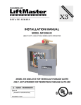
1
FM121
Ñ
&;("5&01&/&3
®
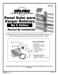
5 Watt
Solar Powered
Battery Charger
Installation Manual
Compatible with all Mighty Mule and GTO/PRO DC Powered Slide and Swing Gate Operators
except for the Mighty Mule 250 (FM250).
All dual gate installations require a minimum of 10 Watts of solar charging power.
Parts Included:
G
$ C
& E
% D
' F
H
$ C
# B
"
A
A.Solar Panel
B.Lag Screws (4)
C.Pipe Clamp (4)
D.Curved Pipe
E. 1/4" Nuts (4)
F. 1/4" x 1/2" Bolt (4)
G. Wire Nuts
H. Compass
Tools Required :
• Slotted (flat blade) Screwdriver
• 7/16" open end wrench
For more information on Mighty Mule’s full line of automatic gate openers and access controls visit our website at www.mightymule.com
RB905
Rev. 11/5/07
Printed in China for GTO, Inc.
©2007 GTO, Inc.
Solar Panel Installation
Step 1: Slide the 1/4" bolts (F) through the bottom of each channel so threaded part of each bolt comes through
top of frame, position the pipe (D) between the bolts and place two clamps (C) over the curved pipe onto the bolts.
The clamp at the top of the solar panel should fit over the pin on the curved pipe. Secure with the 1/4" nuts (E).
Step 2: Determine the site for installation of the solar panel. It is
important to install the solar panel facing the path of the sun where
full sun will strike its face throughout the day. The solar panel cannot
be shaded out or obstructed by trees, bushes, buildings etc for any
part of the day. The curved pipe (D) maintains the proper angle to the
sun. Secure the solar panel assembly to a wooden post or fence using
two pipe clamps (C) and #2 lag screws (B) as shown in the illustration.
If your fence post is metal, you will need alternative hardware not provided, (i.e. U-clamps or metal screws).
IMPORTANT: the solar panel must be positioned facing the path
of the sun, due south and in an open area away from shade. It should
receive at least 8 hours of direct sunlight for a full charge.
HINT: If the solar panel must be placed more than 10 ft. from the
control box (but less than 250 feet away), use multi-stranded, 16
gauge (AWG), direct burial, low-voltage wire RB509 (see Accessory
Catalog). Never use telephone wire or solid core wire.
IMPORTANT: To provide secure and moisture resistant splices for
solar panels use a direct burial splice kit for underground splices and
an above ground splice kit for above ground splices. These splice kits
can be found at hardware and electrical supply stores.
HINTS for Obtaining Maximum Output from Your Solar Panel
1. Place the panel facing due south in the path of the sun, where full sun will strike its face throughout the day(minimum 8 hours).
2. Mount the panel using the curved pipe provided to maintain the proper angle to the sun.
3. For optimal efficiency, wipe the face of the panel frequently with a soft, damp cloth. The output of the
Solar Panel is variable during the day depending on the intensity of the sun and the angle of the rays
striking the panel. The output may vary from a few millivolts to as much as 22 volts. To check the output,
simply disconnect the solar panel leads from the control board and connect them directly to a dc voltmeter.
In bright sunlight the panel output should read at least 18 volts dc at approximately 300mA.
2
Step 3: All Mighty Mule and GTO/PRO DC powered gate operators have a POWER IN terminal on their control
boards marked SOLAR for connecting the solar panel wires. Below are various types of terminals on GTO/PRO
and Mighty Mule control boards, if your control board doesn't have this terminal, please call the GTO's Technical
Service Department at (800)543-1236 or (850)575-4144 for assistance.
Feed the free end of the solar panel wires into the control box and attach them to the SOLAR terminals on the
POWER IN terminal block on the control board. The RED solar panel wire goes to the (+) POSITIVE Solar terminal and the BLACK solar panel wire goes to the (–) NEGATIVE Solar terminal. See diagram below.
J1
J2
FM500, FM502,
SW2500
Control Boards
SW3000/3200,
SW4000/4200
Control Boards
IMPORTANT: Improper installation of these wires will damage to the opener's control board.
J9
~ ~ + NC RLY-COM NO
18 VAC SOLAR RELAY OUT
~ ~
18VAC
– +
SOLAR
Solar Panel Wires
RED
BLK
Solar Panel Wires
Attach RED solar panel wire to the
SOLAR terminal marked (+).
AUX
OUT
18VAC
SOLAR
PANEL
Attach BLACK solar panel wire to the
SOLAR terminal marked (–).
Solar Panel Wires
RED
BLK
SW2000/2002XL,
SW3000/3200XL,
SW4000/4200XL
Control Boards
GTO
FM700, FM702,
SW1000, SW2000,
SL1000, SL2000
Control Boards
FM5350
SW1500
Control Boards
RED
BLK
18VAC SOLAR
~ ~ – +
POWER IN
Solar Panel Wires
RED
BLK
TRANSF
LOCK
AUX
RLY
18 VAC
GTO
LOCK
AUX
or
SOLAR
PWR
~ ~
Solar Panel Wires
RED
BLK
3
Solar Zones and Gate Activity
Use the table and map to determine the
number of operational cycles* per day
to expect in your area, using 5 to 30
Watts of charging power. Figures are
shown for winter (minimum sunlight)
and do not account for the use of any
accessory items.
*An operational cycle is one full
opening and closing of the gate.
*Number of openings per day will
depend on the length, weight, hardware and environmental conditions.
Estimated Gate Openings Per Day
Winter Ratings
Zone 1 Zone 2 Zone 3
Single gate installation with 5 Watts of charging power
Single gate installation with 10 Watts of charging power
Single gate installation with 20 Watts of charging power
Single gate installation with 30 Watts of charging power
Dual gate installation with 10 Watts of charging power
Dual gate installation with 20 Watts of charging power
Dual gate installation with 30 Watts of charging power
4
8
14
20
4
10
16
8
16
28
44
8
18
28
13
26
38
54
13
27
41
All dual gate installations require a minimum of 10 Watts of solar charging power.
Accessories will draw additional power from the battery; the more
accessories you connect, the more power your system will require.
We recommend that you purchase an extra 12V, 7 amp hour battery
(RB500) for the FM500/502, SW2500/2502, SW3000XL/3200XL,
SW4000XL/4200XL
Zone 1
Zone 3
Zone 2
Zone 3
Zone 3
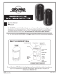
Multiple Panel Installations
NOTE: All connections should
be weather proofed using weather
proof splice kits avilable at hardware and electrical supply stores.
Solar Panels connect in PARALLEL
RED
RED
BLACK
BLACK
attach BLACK to negative (–) solar terminal on control board
attach RED to positive (+) solar terminal on control board
4
Other Mighty Mule and GTO/PRO
Access Controls and Accessories
Push Button Control (FM132)
Unlit doorbell button for remote entry or exit control. Wires directly to the control board and
uses 16 gauge multi-stranded, dual conductor low voltage wire (sold separately).
Pin Lock (FM133)
The Pin Lock substitutes for the clevis pin at the front end of the Mighty Mule® gate
operators. Helps prevent theft of the operator from the gate, while allowing quick release of
the operator.
Key Chain Two Button Transmitter (FM134)
The Key Chain Mini Transmitter is a miniature version of the Mighty Mule® entry transmitter and has the same adjustable code settings. 12 Volt battery included.
Single Button Transmitter (FM135)
The Mighty Mule® entry transmitter, with adjustable code settings, is standard equipment
with all Mighty Mule® systems. 12 Volt battery included.
Digital Keypad (FM137)
1
2
3
4
5
6
7
8
9
The specially designed digital keypad can be easily installed as a wireless or wired keypad.
It can be programmed to use up to 25 different personal identification number (PIN) codes.
Each code is face programmable with additional security features built in. Wired installations require 16 gauge, low voltage, multi-stranded, dual conductor, direct burial wire (sold
separately). Requires 3 AA batteries (not included).
0
Mounting Post (FM100) - In Ground
This black powder coated pedestal is designed to provide convenient access to your keypad,
wireless intercom, or other access control device from your vehicle. With its break down
design it is easy to install and works well in most standard applications. Surface Mount
Flanges (F102) and Extensions (F103) for added height are available.
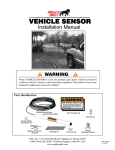
Gate Opening Sensor (FM138)
The Mighty Mule® Gate Opening Sensor is designed for residential and agricultural applications and
is compatible with all Mighty Mule® automatic gate operator models. The wand is an electromagnetic sensor, which offers 'hands free' operation of the Mighty Mule® Gate Operators with a 12 ft.
radius of detection of vehicles in motion.
Automatic Gate Lock Pull-to-Open (FM143)
IC
MAT
CK
AUTO LO
GATE
A MUST for added security. Solenoid driven, with a steel housing. Unlocks and locks
automatically as gates open and close. Used with Mighty Mule® DC swing gate operating
systems for maximum stability and security. Comes with a keyed manual release. Recommended for gates over 8 ft. long. Ideal for animal enclosures or high wind areas.
Wireless Entry Intercom / Keypad (FM136)
Allows owner to screen guest at the gate before allowing access to the property. Keypad
also allows owner to give up to 25 programmable entry codes to family, friends or approved
delivery personnel. Codes can be permanent of temporary. Can be wireless up to 500 feet or
hard wired up to 1000 feet. Additional base stations available (F3101MBC).
5
Other Mighty Mule and GTO/PRO
Access Controls and Accessories
Replacement Battery (FM150)
Standard 12 volt, 7.0 amp-hour, maintenance-free battery for the Mighty Mule® FM500 & FM502
gate operator systems. This is the only battery approved for use with the Mighty Mule® FM500 &
FM502 gate operator systems. Life expectancy is 3-5 years.
Low Voltage Wire (RB509)
The 16 gauge, multi-stranded, dual conductor Low Voltage Wire is for connecting the AC powered
transformer, or the Solar Panel to the control board. Also used for the connection of accessories, such
as locks, keypads, push buttons and other wired control devices. This specially designed wire is UV
treated, PVC coated and ready for direct burial. Available in 50, 100, 250, 500 and 1000 foot rolls.
11" Push to Open Bracket (FM148)
Required when Mighty Mule® 500/502 gate operator(s) must push the gate open, such as on a sloping
driveway or where space prevents gate(s) from opening inward (pulled open). Order two PTO brackets for
conversion of a dual swing gate installation.
Column Mount Lock Receiver (433IH)
For mounting the Automatic Gate Lock on brick columns, walls, or for other applications with limited
space between gate and post.
Replacement Transformer (RB570)
Standard 18 volt, 2200 mA, AC transformer for maintaining the battery included with the Mighty Mule®
gate operator. This is the only transformer approved for use with all UL325 Mighty Mule® gate operator
systems.
Garage Door Receiver (RB709U)
The Garage Door Receiver allows you to use the same Mighty Mule® entry transmitter (see Dual Transmitter) to operate your gate operator and your garage door operator. Compatible with most garage door
operators.
If you have a question about any special order item,
just call 1-800-543-GATE!
3121 Hartsfield Road • Tallahassee, Florida, USA 32303
Telephone GTO Sales: 1-800-543-GATE (4283) or (850) 575-0176 • Fax (850) 575-8912
or GTO Technical Service: 1-800-543-1236 or (850) 575-4144 • Fax (850)575-8950
www.gtoinc.com
The contents of all material available on this installation manual are copyrighted by GTO, Inc. (“GTO”), unless otherwise indicated. All rights are reserved by GTO, and content may not be reproduced,
downloaded, disseminated, published, or transferred in any form or by any means, except with the prior, written permission of GTO. Any reprinting of GTO publications is by permission only. Copyright
infringement is a violation of federal law.
Mighty Mule¨, E-Z Gate¨, GTO¨, are registered trademarks of GTO, Inc. America’s DIY Automatic Gate Openers is a trademark of GTO, Inc. and are the exclusive property of GTO, Inc. (“GTO”).
All rights are reserved by GTO, and these marks may not be used, in any for without the prior, written permission of GTO.