1
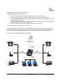
Grandstream Networks, Inc. HT–386 Dual FXS Port Analog Telephone Adaptor HT–386 User Manual Firmware Version 1.0.3.64 www.grandstream.com [email protected] TABLE OF CONTENTS HT–386 USER MANUAL WELCOME ................................................................................................................................................... 4 Safety Compliances.................................................................................................................................. 4 Warranty ................................................................................................................................................... 4 INSTALLATION............................................................................................................................................ 5 Equipment Packaging............................................................................................................................... 5 Connecting Your ATA ............................................................................................................................... 5 Five easy steps to install the HT–386....................................................................................................... 6 PRODUCT OVERVIEW ................................................................................................................................ 7 Key Features............................................................................................................................................. 7 Hardware Specification............................................................................................................................. 9 BASIC OPERATIONS ................................................................................................................................ 10 Get Familiar with Voice Prompt .............................................................................................................. 10 Make Phone Calls................................................................................................................................... 11 Calling Phone or Extension Numbers..................................................................................................... 11 Direct IP Calls ......................................................................................................................................... 12 Call Hold ................................................................................................................................................. 12 Call Waiting............................................................................................................................................. 12 Call transfer............................................................................................................................................. 12 3-way Conferencing................................................................................................................................ 13 PSTN Pass Through............................................................................................................................... 14 Fax Support ............................................................................................................................................ 14 CALL FEATURES ...................................................................................................................................... 15 CONFIGURATION GUIDE ......................................................................................................................... 17 Configuring HT–386 through Voice Prompt............................................................................................ 17 DHCP Mode............................................................................................................................................ 17 Static IP Mode......................................................................................................................................... 17 TFTP Server Address ............................................................................................................................. 17 Firmware Server IP Address................................................................................................................... 17 Configuration Server IP Address ............................................................................................................ 17 Upgrade Protocol.................................................................................................................................... 17 Firmware Upgrade Mode ........................................................................................................................ 17 Configuring HT-386 with Web Browser .................................................................................................. 18 Access the Web Configuration Menu ................................................................................................. 18 End User Configuration .......................................................................................................................... 18 Advanced Configuration and FXS ports Parameters.............................................................................. 21 Saving the Configuration Changes......................................................................................................... 26 REBOOTING THE HT–386 FROM REMOTE .............................................................................................. 26 Configuration through a Central Server.................................................................................................. 27 SOFTWARE UPGRADE ............................................................................................................................ 28 Firmware Upgrade through TFTP/HTTP ................................................................................................ 28 IVR METHOD ........................................................................................................................................ 28 UPGRADE THROUGH TFTP.................................................................................................................... 28 NO LOCAL TFTP SERVER ..................................................................................................................... 28 Configuration File Download................................................................................................................... 29 Firmware and Configuration File Prefix and Postfix ............................................................................... 29 Managing Firmware and Configuration File Download .......................................................................... 29 RESTORE FACTORY DEFAULT SETTING.............................................................................................. 30 Reset Via the Reset Button .................................................................................................................... 30 Reset Via IVR ......................................................................................................................................... 30 GLOSSARY OF TERMS ............................................................................................................................ 31 Grandstream Networks, Inc. HT-386 User Manual Firmware 1.0.3.64 Page 2 of 34 Last Updated: 2/2007 TABLE OF FIGURES HT–386 USER MANUAL FIGURE 1: FIGURE 2: FIGURE 3: FIGURE 4: FIGURE 5: CONNECTING THE HT–386 ............................................................................................................ 5 INTERCONNECTION DIAGRAM OF THE HT–386 ................................................................................ 6 SCREENSHOT OF CONFIGURATION LOG-IN PAGE ............................................................................ 18 SCREENSHOT OF CONFIGURATION UPDATE MODE ......................................................................... 26 SCREENSHOT OF REBOOTING SCREEN........................................................................................... 27 TABLE OF TABLES HT–386 USER MANUAL TABLE 1: DEFINITIONS OF THE HT–386 CONNECTORS ..................................................................................... 5 TABLE 2: HT–386 TECHNICAL SPECIFICATIONS ............................................................................................... 8 TABLE 3: HT–386 HARDWARE SPECIFICATION ................................................................................................. 9 TABLE 4: HT–386 IVR MENU DEFINITIONS .................................................................................................... 10 TABLE 5: HT–386 CALL FEATURE DEFINITIONS ............................................................................................. 15 TABLE 6: HT–386 LED DEFINITIONS ............................................................................................................. 16 TABLE 7: HT–386 DEVICE STATUS PAGE DEFINITIONS................................................................................... 19 TABLE 8: HT–386 BASIC SETTINGS PAGE DEFINITIONS .................................................................................. 20 TABLE 9: HT–386 ADVANCED SETTINGS PAGE DEFINITIONS .......................................................................... 21 TABLE 10: HT–386 FXS PORT1/FXS PORT2 SETTINGS PAGES DEFINITIONS .............................................. 23 TABLE 11: HT–386 CALL PROGRESS TONES SETTINGS PAGE DEFINITIONS .................................................... 26 TABLE OF GUI INTERFACES HT–386 USER MANUAL (http://www.grandstream.com/GUI/GUI_HT386.rar) 1. 2. 3. 4. 5. 6. 7. 8. 9. SCREENSHOT OF CONFIGURATION LOGIN PAGE STATUS CONFIGURATION PAGE DEFINITIONS SCREENSHOT OF BASIC SETTINGS CONFIGURATION PAGE SCREENSHOT OF ADVANCED SETTINGS CONFIGURATION PAGE SCREENSHOT OF FXS1 ACCOUNT CONFIGURATION SCREENSHOT OF FXS2 ACCOUNT CONFIGURATION SCREENSHOT OF CALL PROGRESS TONES CONFIGURATION PAGE SCREENSHOT OF SAVED CONFIGURATION CHANGES SCREENSHOT OF REBOOT PAGE Grandstream Networks, Inc. HT-386 User Manual Firmware 1.0.3.64 Page 3 of 34 Last Updated: 2/2007 WELCOME Grandstream HandyTone Analog Telephone Adapters/IAD series offers a comprehensive line of affordable VoIP access devices based on Grandstream’s innovative technology platform. The HandyTone series offers the entry-level IP Telephony user superb audio quality, rich functionalities, interoperability with the leading 3rd party VoIP providers, and compatibility with most service providers. The HandyTone series is ultra-compact, works with any PSTN or cordless phone and fax machines and offers the simplicity of plug and dial, making it ideal for the basic IP telephony user. HandyTone 386 is a next generation VoIP integrated access device based on SIP standard, that supports dual- FXS ports each, with an independent SIP account or SIP server platform, and a PSTN pass through line for toggling operations between SIP and PSTN networks. HandyTone 386 features market-leading superb sound quality, rich functionalities, and a compact design. SAFETY COMPLIANCES The HT–386 adaptor complies with FCC/CE and various safety standards. The HT–386 power adaptor is compliant with UL standard. Only use the universal power adapter provided with the HT–386 package. The manufacturer’s warranty does not cover damages to the phone caused by unsupported power adaptors. WARRANTY If you purchased your HT–386 from a reseller, please contact the company where you purchased your phone for replacement, repair or refund. If you purchased the product directly from Grandstream, contact your Grandstream Sales and Service Representative for a RMA (Return Materials Authorization) number before you return the product. Grandstream reserves the right to remedy warranty policy without prior notification. Warning: Changes or modifications to this product not expressly approved by Grandstream, or operation of this product in any way other than as detailed by this User Manual, could void your manufacturer warranty. Please do not use a different power adaptor with the HT–386 as it may cause damage to the products and void the manufacturer warranty. • This document is contains links to Grandstream GUI Interfaces. Please download these examples http://www.grandstream.com/user_manuals/GUI/GUI_HT386.rar for your reference. • This document is subject to change without notice. The latest electronic version of this user manual is available for download @: http://www.grandstream.com/user_manuals/HT386_User_Manual.pdf Reproduction or transmittal of the entire or any part, in any form or by any means, electronic or print, for any purpose without the express written permission of Grandstream Networks, Inc. is not permitted. Grandstream Networks, Inc. HT-386 User Manual Firmware 1.0.3.64 Page 4 of 34 Last Updated: 2/2007 INSTALLATION EQUIPMENT PACKAGING The HT–386 ATA package contains: • • • One HT–386 Main Case One Universal Power Adaptor One Ethernet Cable CONNECTING YOUR ATA HT-386 Analog Telephone Adaptor is an all-in-one VoIP integrated device designed to be a total solution for networks providing VoIP services. The HT-386 VoIP features are available using a regular analog telephone. FIGURE 1: CONNECTING THE HT-386 LED (green/red) +5V/1200mA RJ-11 FXS Port (Phone) RJ-11 PSTN Line RJ-45 10M Ethernet LAN/WAN TABLE 1: DEFINITIONS OF THE HT–386 CONNECTORS +5V/1.2A Power adapter connection LAN Port (RJ-45) Connect to the internal LAN network or router. PHONE1 (RJ-11) FXS port to be connected to analog phones / fax machines. PHONE2 (RJ-11) FXS port to be connected to analog phones / fax machines. LINE (RJ-11) FXO port should be connected to the PSTN line BUTTON Button and two colors led indicator. Grandstream Networks, Inc. HT-386 User Manual Firmware 1.0.3.64 Page 5 of 34 Last Updated: 2/2007 FIVE EASY STEPS TO INSTALL THE HT–386 Following are the steps to install a HT–386: 1. Connect a standard touch-tone analog telephone (or fax machine) to FXS port 1. 2. Connect another standard touch-tone analog telephone (or fax machine) to FXS port 2. 3. Insert a standard telephone cable into the LINE port of HT–386. and connect the other end of the telephone cable to a wall jack. 4. Insert the Ethernet cable into the LAN port of HT–386. and connect the other end of the Ethernet cable to an uplink port (a router or a modem, etc.) 5. Insert the power adapter into the HT–386 and connect it to a wall outlet. For more information, see Configuring the HT–386. The HT–386 is easy to configure and easy to interconnect with your existing communication devices.HT– 386 has two FXS ports and one RJ-11 jack on the side that is a LINE port, used as a PSTN pass-through port. Each FXS port has a separate SIP account which allows both ports to make calls concurrently. FIGURE 2: INTERCONNECTION DIAGRAM OF THE HT–386 Internet ADSL/Cable Modem Ethernet Analog Phone FXS Cordless Phone FXS LAN Fax Grandstream Networks, Inc. Analog Phone WAN Cordless Phone Fax HT-386 User Manual Firmware 1.0.3.64 Page 6 of 34 Last Updated: 2/2007 PRODUCT OVERVIEW The HT–386 is a next generation dual-port SIP IAD for Internet data, voice, and fax. It supports two (2) FXS ports, each with an independent SIP account or SIP server platform, and a PSTN pass through line for toggling operations between SIP and PSTN networks. The HT–386 offers the entry-level IP telephony user superb audio quality, rich functionalities, interoperability with the leading 3rd party VoIP providers, and compatibility with most service providers. The HandyTone is compact, works with any PSTN or cordless phone and fax machines and offers the simplicity of plug and dial, making it ideal for the basic IP telephony user. KEY FEATURES Ethernet Ports DHCP FXS Port PSTN Pass – through Voice Mail Indicator Voice Codec Remote Configuration 1 RJ45 (LAN) Client 2 Yes Yes iLBC, G.723, G.711, G.729, G.726, T.38 TFTP/HTTP Grandstream Networks, Inc. HT-386 User Manual Firmware 1.0.3.64 Page 7 of 34 Last Updated: 2/2007 TABLE 2: HT–386 TECHNICAL SPECIFICATIONS Lines/SIP Accounts Protocol Support Feature Keys LAN/WAN Interface Device Management 2 lines / 2 SIP accounts SIP 2.0 (RFC 3261), TCP/UDP/IP, RTP/RTCP, HTTP, ARP/RARP, ICMP, DNS, DHCP, NTP, TFTP, PPPoE protocols 1 button RJ-45 10 Mbps Web interface or via secure (AES encrypted) central configuration file for mass deployment Support device configuration via built-in IVR, Web browser or central configuration file through TFTP or HTTP Support Layer 2 (802.1Q, VLAN, 802.1p) and Layer 3 QoS (ToS, DiffServ, MPLS) Auto/manual provisioning system NAT-friendly remote software upgrade (via TFTP/HTTP) for deployed devices including behind firewall/NAT Syslog support DHCP Server/Client Yes, Client Audio Features Advanced Digital Signal Processing (DSP) Dynamic negotiation of codec and voice payload length Support for G.723,1 (5.3K/6.3K), G.729A, G.711 µ/A, G.726, and iLBC codecs In-band and out-of-band DTMF ((in audio, RFC2833, SIP INFO) Silence Suppression, VAD (voice activity detection), CNG (comfort noise generation), ANG (automatic gain control) Adaptive jitter buffer control Packet delay & loss concealment Support volume amplification Support configurable Call Progress Tones Caller ID display or block, Call waiting caller ID, Call waiting/flash, Call transfer, hold, forward, mute, 3-way conferencing Manual or dynamic host configuration protocol (DHCP) network setup; RTP and NAT support traversal via STUN T.38 compliant Group 3 Fax Relay up to 14.4kpbs and auto-switch to G.711 for Fax Pass-through (pending), Fax Datapump V.17, V.19, V.27ter, V.29 for T.38 fax relay Call Handling Features Network and Provisioning Fax over IP Security Physical Design Grandstream Networks, Inc. DIGEST authentication and encryption using MD5 and MD5-sess Stylish and compact design; small universal power supply, ideal for travel HT-386 User Manual Firmware 1.0.3.64 Page 8 of 34 Last Updated: 2/2007 HARDWARE SPECIFICATION TABLE 3: HT-386 HARDWARE SPECIFICATION LAN interface FXS telephone port PSTN Port Button LED Universal Switching Power Adaptor Dimension Weight Temperature Humidity 1xRJ45 10Base-T 2 x FXS 1x PSTN pass-through or life line port 1 Green and Red color Input: 100-240VAC 50-60 Hz Output: +5VDC, 1200mA UL certified 70mm (W) x 130mm (D) x 27mm (H) 0.6lbs (0.3kg) 40 - 130oF / 5 – 45oC 10% - 90% (non-condensing) Compliance Grandstream Networks, Inc. HT-386 User Manual Firmware 1.0.3.64 Page 9 of 34 Last Updated: 2/2007 BASIC OPERATIONS GET FAMILIAR WITH VOICE PROMPT The HT–386 has a stored voice prompt menu for quick browsing and simple configuration. Currently, the voice prompt menu and the LED button is designed for FXS Port 1 ONLY. To enter this voice prompt menu, press the LED button or press “***” from the analog phone. TABLE 4: HT-386 IVR MENU DEFINITIONS Menu Voice Prompt Options Main Menu “Enter a Menu Option” Press “*” for the next menu option Press “#” to return to the main menu Enter 01-06, 47, 86, 99 menu options 01 “DHCP Mode”, “Static IP Mode” Press “9” to toggle the selection If using “Static IP Mode”, configure the IP address information using menus 02 to 05. If using “Dynamic IP Mode”, all IP address information comes from the DHCP server automatically after reboot. 02 “IP Address “ + IP address The current WAN IP address is announced If using “Static IP Mode”, enter 12 digit new IP address. 03 “Subnet “ + IP address Same as menu 02 04 “Gateway “ + IP address Same as menu 02 05 “DNS Server “ + IP address Same as menu 02 07 Preferred Vocoder Press “9” to move to the next selection in the list: • PCM U / PCM A • G.723 • G.729 • G.726 • iLBC 12 WAN Port Web Access Press “9” to toggle between enable / disable 13 Firmware Server IP Address Announces current Firmware Server IP address. Enter 12 digit new IP address. 14 Configuration Server IP Address Announces current Config Server Path IP address. Enter 12 digit new IP address. 15 Upgrade Protocol Upgrade protocol for firmware and configuration update. Press “9” to toggle between TFTP / HTTP 16 Firmware Version Firmware version information. 17 Firmware Upgrade Firmware upgrade mode. Press “9” to toggle among the following three options: - always check - check when pre/suffix changes - never upgrade Grandstream Networks, Inc. HT-386 User Manual Firmware 1.0.3.64 Page 10 of 34 Last Updated: 2/2007 47 “Direct IP Calling” Enter a 12 digit IP address to make a direct IP call, after dial tone. (See “Make a Direct IP Call”.) 99 “RESET” Press “9” to reboot the device; or Enter encoded MAC address to restore factory default setting (See “Restoring Factory Settings”) “Invalid Entry” Automatically returns to main menu NOTE: • Once the button is pressed, you will hear the voice prompt main menu. If the button is pressed again, while it is already in the voice prompt menu, it jumps to “Direct IP Call” option and a dial tone is prompted • “*” shifts down to the next menu option • “#” returns to the main menu • “9” functions as the ENTER key in many cases to confirm an option • All entered digit sequences have known lengths - 2 digits for menu option and 12 digits for IP address. For IP address, add 0 before the digits if the digits are less than 3 (like 192.168.0.26 should be key in like 192168000026, no dot needed while input). Once all of the digits are collected, the input will be processed. • Key entry can not be deleted but the phone may prompt error once it is detected MAKE PHONE CALLS CALLING PHONE OR EXTENSION NUMBERS There are currently two methods to make an extension number call: a) Dial the numbers directly and wait for 4 (default) seconds. b) Dial the numbers directly, and press # (assuming that “use # as dial key is selected in web configuration). Examples: • To dial another extension on the same proxy, such as 1008, simply pick up the attached phone, dial 1008 and then press the # or wait for 4 seconds. • To dial a PSTN number such as 6266667890, you might need to enter in some prefix number followed by the phone number. Please check with your VoIP service provider to get the information. If you phone is assigned with a PSTN-like number such as 6265556789, most likely you just follow the rule to dial 16266667890 as if you were calling from a regular analog phone of North America, then followed by pressing # or wait for 4 seconds. Grandstream Networks, Inc. HT-386 User Manual Firmware 1.0.3.64 Page 11 of 34 Last Updated: 2/2007 DIRECT IP CALLS Direct IP calling allows two parties, that is, a HT with an analog phone and another VoIP Device, to talk to each other in an ad hoc fashion without a SIP proxy. This kind of VoIP calls can be made between two parties if: • • • Both the HT–386 and other VoIP Device(i.e., another HT ATA or Budgetone SIP phone or other VoIP unit) have public IP addresses, or Both the HT–386 and other VoIP Device are on the same LAN using private IP addresses, or Both the HT–386 and other VoIP Device can be connected through a router using public or private IP addresses (with necessary port forwarding or DMZ). To make a direct IP call, first pick up the analog phone or turn on the speakerphone on the analog phone, then access the voice menu prompt by dial “***” or press the button on the HT-286, and dials “47” to access the direct IP call menu. User will hear a voice prompt “Direct IP Calling” and a dial tone. Enter a 12-digit target IP address to make a call. Destination ports can be specified by using “*4” (encoding for “:”) followed by the port number. Examples: 1. If the target IP address is 192.168.0.10, the dialing convention is Voice Prompt with option 47, then 192 168 000 010 followed by the “#” key if it is configured as a send key or wait for more than 5 seconds. 2. If the target IP address/port is 192.168.1.20:5062, then the dialing convention would be: Voice Prompt with option 47, then 192168001020*45062 followed by the “#” key if it is configured as a send key or wait for 4 seconds. NOTE: • When completing a direct IP call, the “Use Random Port” should set to “NO”. • You can NOT make direct IP calls between FXS1 to FXS2 since they are using same IP. CALL HOLD Place a call on hold by pressing the “flash” button on the analog phone (if the phone has that button). Press the “flash” button again to release the previously held Caller and resume conversation. If no “flash” button is available, use “hook flash” (toggle on-off hook quickly). You may drop a call using hook flash. CALL WAITING Call waiting tone (3 short beeps) indicates an incoming call, if the call waiting feature is enabled. Toggle between incoming call and current call by pressing the “flash” button. First call is placed on hold. Press the “flash” button to toggle between two active calls. CALL TRANSFER Assume that call Caller A and B are in conversation. A wants to Blind Transfer B to C: 1. Caller A presses FLASH on the analog phone to hear the dial tone. 2. Caller A dials *87 then dials caller C’s number, and then # (or wait for 4 seconds) 3. Caller A will hear the confirm tone. Then, A can hang up. Grandstream Networks, Inc. HT-386 User Manual Firmware 1.0.3.64 Page 12 of 34 Last Updated: 2/2007 NOTE: “Enable Call Feature” must be set to “Yes” in web configuration page. Caller A can place a call on hold and wait for one of three situations: 1. A quick confirmation tone (similar to call waiting tone) followed by a dial tone. This indicates the transfer is successful (transferee has received a 200 OK from transfer target). At this point, Caller A can either hang up or make another call. 2. A quick busy tone followed by a restored call (on supported platforms only). This means the transferee has received a 4xx response for the INVITE and we will try to recover the call. The busy tone is just to indicate to the transferor that the transfer has failed. 3. Continuous busy tone. The phone has timed out. Note: continuous busy tone does not indicate the transfer has been successful, nor does it indicate the transfer has failed. It often means there was a failure to receive second NOTIFY – check firmware for most recent release. Attended Transfer Assume that Caller A and B are in conversation. Caller A wants to Attend Transfer B to C: 1. Caller A presses FLASH on the analog phone for dial tone. 2. Caller A then dials Caller C’s number followed by # (or wait for 4 seconds). 3. If Caller C answers the call, Caller A and Caller C are in conversation. Then A can hang up to complete transfer. 4. If Caller C does not answer the call, Caller A can press “flash” to resume call with Caller B. NOTE: When Attended Transfer fails and A hangs up, the HT-502 will ring back user A to remind A that B is still on the call. A can pick up the phone to resume conversation with B. 3-WAY CONFERENCING Star Code Style 3-way Conference Assuming that call party A and B are in conversation. A wants to bring C in a conference: 1. 2. 3. 4. A presses FLASH (on the analog phone, or Hook Flash for old model phones) to get a dial tone. A dials *23 then C’s number then # (or wait for 4 seconds). If C answers the call, then A press “flash” to bring B, C in the conference. If C does not answer the call, A can press “flash” back to talk to B. Bellcore Style 3-way Conference Bellcore style 3-way conference is also supported. To do this, user needs to enable “Use Bell-style 3-way Conference” in FXS1 or FXS2 web configuration. Assuming that call party A and B are in conversation. A wants to bring C in a conference: 1. A presses FLASH (on the analog phone, or Hook Flash for old model phones) to get a dial tone. 2. A dials C’s number then # (or wait for 4 seconds). 3. If C answers the call, then A press “flash” to bring B, C in the conference. 4. If C does not answer the call, A can press “flash” back to talk to B. Grandstream Networks, Inc. HT-386 User Manual Firmware 1.0.3.64 Page 13 of 34 Last Updated: 2/2007 PSTN PASS THROUGH HT-386 supports PSTN pass through on FXS port 1. User can make and receive PSTN calls with attached analog phone in Phone 1 port. Phone 2 port (or FXS port 2) does NOT have this feature. • • To receive PSTN calls, simply make phone off hook when the analog phone rings. To make a PSTN call, simply press the PSTN access code (*00 is default, or any number configured in web configuration page) to switch to the PSTN line and get dial tone, then dial the number. FAX SUPPORT HT–386 supports FAX in two modes: T.38 (Fax over IP) and fax pass through. T.38 is the preferred method because it is more reliable and works well in most network conditions. If the service provider supports T.38, please use this method by selecting Fax mode to be T.38 (default). If the service provider does not support T.38, pass-through mode may be used. To send or receive faxes in fax pass through mode, users must select all the Preferred Codecs to be PCMU/PCMA (G.711-u/a). Grandstream Networks, Inc. HT-386 User Manual Firmware 1.0.3.64 Page 14 of 34 Last Updated: 2/2007 CALL FEATURES Following table shows the call features (* code) of HT-386. TABLE 5: HT–386 CALL FEATURE DEFINITIONS Key *23 *50 *51 Call Features 3 way Conferencing Refer section above above for procedure to perform 3 way Calling. Block Caller ID (for all subsequent calls) Send Caller ID (for all subsequent calls) Block Caller ID (per call). Dial “*67” + ” number ”. No dial tone will be played in the middle. Send Caller ID (per call). Dial “*82” + ” number ”. No dial tone will be played in the middle. Disable Call Waiting (for all-config change) Enable Call Waiting (for all-config change) *70 Disable Call Waiting (Per Call) *71 Enable Call Waiting (Per Call) *72 Unconditional Call Forward. To use this feature, dial “*72”, wait for the dial tone. Then dial the forward number ended with #, wait for dial tone, hang up. Cancel Unconditional Call Forward To cancel “Unconditional Call Forward”, dial “*73” and get the dial tone, then hang up. *30 *31 *67 *82 *73 *87 Blind Transfer Refer to section above for procedure to perform Blind Transfer. *90 Busy Call Forward To use this feature, dial “*90”, wait for the dial tone. Then dial the forward number ended with #, wait for dial tone, hang up. Cancel Busy Call Forward To cancel “Busy Call Forward”, dial “*91” and get the dial tone, then hang up *91 *92 *93 Flash/Hook Delayed Call Forward To use this feature, dial “*92”, wait for the dial tone. Then dial the forward number ended with #, wait for dial tone, hang up. Cancel Delayed Call Forward To cancel this Forward, dial “*93” and get the dial tone, then hang up Toggles between active call and incoming call (call waiting tone). If not in conversation, flash/hook will switch to a new channel for a new call. Grandstream Networks, Inc. HT-386 User Manual Firmware 1.0.3.64 Page 15 of 34 Last Updated: 2/2007 LED LIGHT PATTERN INDICATION Following tables show the LED light pattern indication. The LED shows PHONE1 status only. TABLE 6: HT–386 LED DEFINITIONS RED LED indicates not normal status Button flashes every 2 seconds. (if DHCP is configured) DHCP Failed or WAN No Cable Button flashes every 2 seconds. (if SIP server is configured) HT–496fails to register Button flashes every 2 seconds. Red light steady. Firmware Upgrading Device Malfunctions GREEN LED indicates normal status Button flashes every 2 seconds. Button flashes at 1/10 second. Button flashes every second. Green light steady. Grandstream Networks, Inc. Message Waiting Indication RINGING RINGING INTERVAL In Conversation HT-386 User Manual Firmware 1.0.3.64 Page 16 of 34 Last Updated: 2/2007 CONFIGURATION GUIDE CONFIGURING HT–386 THROUGH VOICE PROMPT DHCP MODE Follow Table 3 with voice menu option 01 to enable HT-386 to use DHCP. STATIC IP MODE Follow Table 3 with voice menu option 01 to enable HT-386 to use STATIC IP mode, then use option 02, 03, 04 to set up HT-386’s IP, Subnet Mask, Gateway respectively. TFTP SERVER ADDRESS Follow Table 3 with voice menu option 06 to configure the IP address of the TFTP server. FIRMWARE SERVER IP ADDRESS Select voice menu option 13 to configure the IP address of the firmware server. CONFIGURATION SERVER IP ADDRESS Select voice menu option 14 to configure the IP address of the configuration server. UPGRADE PROTOCOL Select voice menu option 15 to choose firmware and configuration upgrade protocol. User can choose between TFTP and HTTP. FIRMWARE UPGRADE MODE Select voice menu option 17 to choose firmware upgrade mode among the following three options: 1) always check, 2) check when pre/suffix changes, and 3) never upgrade Grandstream Networks, Inc. HT-386 User Manual Firmware 1.0.3.64 Page 17 of 34 Last Updated: 2/2007 CONFIGURING HT-386 WITH WEB BROWSER The HT–386 has an embedded Web server that will respond to HTTP GET/POST requests. It also has embedded HTML pages that allow users to configure the HT–386 through a Web browser such as Microsoft’s IE, AOL’s Netscape or Mozilla Firefox installed on Windows or Unix OS. (Macintosh OS does not included). Access the Web Configuration Menu First, get the IP address of the HT-386 through section “Configuration” with menu option 02. Then access the HT-386’s Web Configuration Menu using the following URLI: http://ATA-IP-Address where the ATAIP-Address is the IP address of the HT-386. NOTE: • To type IP address into browser to get the configuration page, please strip out the announced leading “0” as the browser will parse in octet. e.g.: if the IP address reported: 192.168.001.014, please type in: 192.168.1.14. END USER CONFIGURATION Once the HTTP request is entered and sent from a Web browser, the user will see a log-in screen. There are two default passwords for the login page: User Level: End User Level Administrator Level Password: 123 admin Web pages allowed: Only Status and Basic Settings Browse all pages Only an administrator can access the “ADVANCED SETTING” configuration page. Once this HTTP request is entered and sent from a Web browser, the HT-386 will respond with the following login screen: FIGURE 3: SCREENSHOT OF CONFIGURATION LOG-IN PAGE Grandstream Networks, Inc. HT-386 User Manual Firmware 1.0.3.64 Page 18 of 34 Last Updated: 2/2007 The password is case sensitive with maximum length of 25 characters. The factory default password for End User and administrator is “123” and “admin” respectively. Only administrator can get access to the “ADVANCED SETTING” configuration page. NOTE: 1. If you CAN NOT log into the configuration page by using default password, please check with the VoIP service provider. Most likely the VoIP service provider has provisioned the device and configured for you therefore the password has already been changed. After a correct password is entered in the login screen, the embedded Web server inside the HT-386 will respond with the Configuration pages which are explained in details below. TABLE 7: HT-386 DEVICE STATUS PAGE DEFINITIONS MAC Address IP Address Product Model Software Version System Uptime Registered PPPoE Link Up NAT Grandstream Networks, Inc. The device ID, in HEX format. This is very important ID for ISP troubleshooting. This field shows IP address of the HT-386. This field contains the product model info, such as HT-386. Program: This is the main software release. This number is always used for firmware upgrade. Current release is 1.0.3.64 Bootloader: current version is 1.1.0.1. HTML: current version 1.0.3.64. VOC: current version is 1.0.0.13 This shows system up time since last reboot. Whether the unit is registered to service provider’s server. This shows whether the PPPoE is up if connected to DSL modem This shows what kind NAT the HT-386 is connected to. It is based on STUN protocol. If the detected NAT is symmetric NAT, STUN will not work and Outbound Proxy needed to make HT-386 functioning correctly. HT-386 User Manual Firmware 1.0.3.64 Page 19 of 34 Last Updated: 2/2007 TABLE 8: HT-386 BASIC SETTINGS PAGE DEFINITIONS End User Password Web Port IP Address This contains the password for end user to access the Web Configuration Menu. User can put new password here. This field is case sensitive with maximum of 25 characters This is the device’s internal HTTP server port. Default is 80. - If DHCP mode is enabled, then all the field values for the Static IP mode are not used (even though they are still saved in the Flash memory.) The HT-386 will acquire its IP address from DHCP in the network. PPPoE settings is usually for DSL/ADSL modem users. The HT will attempt to establish a PPPoE session if PPPoE account is set. DHCP hostname DHCP domain DHCP vendor class ID Time Zone Daylight Savings Time - If Static IP mode is selected, the IP address, Subnet Mask, Default Router IP address, DNS Server 1 (mandatory), DNS Server 2 (optional) fields need to be configured. This option specifies the name of the client. This field is optional but may be required by some Internet Service Providers. Default is blank. This option specifies the domain name that client should use when resolving hostnames via the Domain Name System. Default is blank. This option is used by clients and servers to exchange vendor-specific information. Default is blank. This parameter controls how the displayed date/time will be adjusted according to the specified time zone. This parameter controls whether the displayed time will be daylight savings time or not. If set to “Yes” and the Optional Rule is empty, then the displayed time will be 1 hour ahead of normal time. The “Automatic Daylight Saving Time Rule” shall have the following syntax: start-time;end-time;saving Both start-time and end-time have the same syntax: month,day,weekday,hour,minute month: 1,2,3,..,12 (for Jan, Feb, .., Dec) day: [+|-]1,2,3,..,31 weekday: 1, 2, 3, .., 7 (for Mon, Tue, .., Sun), or 0 which means the daylight saving rule is not based on week days but based on the day of the month. hour: hour (0-23), minute: minute (0-59) If “weekday” is 0, it means the date to start or end daylight saving is at exactly the given date. In that case, the “day” value must not be negative. If “weekday” is not zero and “day” is positive, then the daylight saving starts on the first “day”th iteration of the weekday (1st Sunday, 3rd Tuesday etc). If “weekday” us not zero and “day” is negative, then the daylight saving starts on the last “day”th iteration of the weekday (last Sunday, 3rd last Tuesday etc). The saving is in the unit of minutes. The saving time may also be preceded by a negative (-) sign if subtraction is desired instead of addition. The default value for “Automatic Daylight Saving Time Rule” shall be set to “04,01,7,02,00;10,-1,7,02,00;60” which is the rule for US. Examples Grandstream Networks, Inc. HT-386 User Manual Firmware 1.0.3.64 Page 20 of 34 Last Updated: 2/2007 PSTN Access Code US/Canada where daylight saving time is applicable: 04,01,7,02,00;10,-1,7,02,00;60 This means the daylight saving time starts from the first Sunday of April at 2AM and ends the last Sunday of October at 2AM. The saving is 60 minutes (1hour). Default is “*00”, user can change it. By pressing the code user can switch the phone to PSTN line connected to the Line port of ATA and make PSTN outgoing calls. This is called PSTN Pass Through. ADVANCED CONFIGURATION AND FXS PORTS PARAMETERS To login to the Advanced Setting and FXS port configuration pages, administrator password is required. The default administrator password is “admin”. User can change the administrator password here. The password is case sensitive and the maximum length is 25 characters. TABLE 9: HT-386 ADVANCED SETTINGS PAGE DEFINITIONS Admin Password Home NPA Layer 3 QoS Layer 2 QoS No Key Entry timeout STUN Server Keep-alive interval Use NAT IP Firmware Upgrade and Provisioning Firmware Server Path Config Server Path Firmware File Prefix Firmware File Postfix Config File Prefix Config File Postfix Automatic Upgrade Firmware Key Caller ID Scheme Grandstream Networks, Inc. Administrator password. Only administrator can configure the “Advanced Settings” page. Password field is purposely blanked for security reason after clicking update and saved. The maximum password length is 25 characters. Local area code for North American Dial Plan. This field defines the layer 3 QoS parameter which can be the value used for IP Precedence or Diff-Serv or MPLS. Default value is 48. Layer 2 QoS settings. Default setting is blank. Other VLAN supported equipments required if configured these settings. Default is 4 seconds. User can short or extend that depends on digits dialed IP address or Domain name of the STUN server. Default is 20 seconds. The interval of sending dummy UDP packet to keep NAT “pin hole” open. NAT IP address used in SIP/SDP message. Default is blank. Default method is HTTP. Firmware upgrade may take up to 10 minutes depending on network environment. Do not interrupt the firmware upgrading process. IP address or domain name of firmware server. IP address or domain name of configuration server. Default is blank. If configured, HT-386 will request the firmware file with the prefix. This setting is useful for ITSPs. End user should keep it blank. Default is blank. End user should keep it blank. Default is blank. End user should keep it blank. Default is blank. End user should keep it blank. Default is “Yes”. For firmware encryption. It should be 32 digit in Hexadecimal Representation. End user should keep it blank. • Bellcore (North America) • CID (Canada) • DTMF (Brazil) • DTMF (Sweden) • DTMF (Denmark) HT-386 User Manual Firmware 1.0.3.64 Page 21 of 34 Last Updated: 2/2007 Onhook Voltage Polarity Reversal NTP server Syslog Server Syslog Level • ETSI-DTMF (Finland, Sweden) • ETSI-FSK (France, Germany, Norway, Taiwan, UK-CCA) Select the onhook voltage to suit different area or PBX. Default is No. If set to Yes, polarity will be reversed upon call establishment and termination. URI or IP address of the NTP (Network Time Protocol) server, which the HT386 will use to synchronize the date/time. The IP address or URL of syslog server, especially useful for ITSP (Internet Telephone Service Provider) Select the ATA to report the log level. Default is NONE. The level is either one of DEBUG, INFO, WARNING or ERROR. Syslog messages are sent based on the following events: • • • • • • • • • • product model/version on boot up (INFO level) NAT related info (INFO level) sent or received SIP message (DEBUG level) SIP message summary (INFO level) inbound and outbound calls (INFO level) registration status change (INFO level) negotiated codec (INFO level) Ethernet link up (INFO level) SLIC chip exception (WARNING and ERROR levels) memory exception (ERROR level) The Syslog uses USER facility. In addition to standard Syslog payload, it contains the following components: GS_LOG: [device MAC address][error code] error message Here is an example: May 19 02:40:38 192.168.1.14 GS_LOG: [00:0b:82:00:a1:be][000] Ethernet link is up Grandstream Networks, Inc. HT-386 User Manual Firmware 1.0.3.64 Page 22 of 34 Last Updated: 2/2007 TABLE 10: HT-386 FXS PORT1/FXS PORT2 SETTINGS PAGES DEFINITIONS SIP Server Outbound Proxy SIP User ID Authenticate ID Authentication Password Name Use DNS SRV: User ID is Phone Number SIP Registration Unregister On Reboot Register Expiration Local SIP port Local RTP port Use Random Port DTMF Payload Type Send DTMF Grandstream Networks, Inc. This field contains the URI string or the IP address (and port, if different from 5060) of the SIP proxy server. e.g., the following are some valid examples: sip.my-voip-provider.com, or sip:my-company-sip-server.com, or 192.168.1.200:5066 IP address or Domain name of Outbound Proxy, or Media Gateway, or Session Border Controller. Used by ATA for firewall or NAT penetration in different network environment. If symmetric NAT is detected, STUN will not work and ONLY Outbound Proxy will work. User account information, provided by VoIP service provider (ITSP), usually has the form of digit similar to phone number or actually a phone number. This field contains the user part of the SIP address for this phone. e.g., if the SIP address is sip:my_user_id@my_provider.com, then the SIP User ID is: my_user_id. Do NOT include the preceding “sip:” scheme or the host portion of the SIP address in this field. ID used for authentication, usually same as SIP user ID, but could be different and decided by ITSP. Password for ATA to register to (SIP) servers of ITSP. Purposely blank out once saved for security. Maximum length is 25. User name, not user ID, for information only. Default is No. If set to Yes the client will use DNS SRV to lookup for the server If the HT-386 has an assigned PSTN telephone number, this field should be set to “Yes”. Otherwise, set it to “No”. . If set to yes, a “user=phone” parameter will be attached to the “From” header in SIP request This parameter controls whether the HT-386 needs to send REGISTER messages to the proxy server. The default setting is “Yes”. Default is No. If set to Yes, the device will first send registration request to indicate SIP registra to remove previous bindings. This parameter allows the user to specify the time frequency (in minutes) the HT-386 will refresh its registration with the specified registrar. The default interval is 60 minutes (or 1 hour). The maximum interval is 65535 minutes (about 45 days). This parameter defines the local SIP port the HT-386 will listen and transmit. The default value is for FXS1 is 5060, FXS2 is 5062 This parameter defines the local RTP-RTCP port pair the HT-386 will listen and transmit. It is the base RTP port for channel 0. When configured, channel 0 will use this port_value for RTP and the port_value+1 for its RTCP; channel 1 will use port_value+2 for RTP and port_value+3 for its RTCP. The default value for FXS1 is 5004, FXS2 is 5008. Default No. If set to Yes, the device will pick randomly-generated SIP and RTP ports. This is usually necessary when multiple SIP devices are behind the same NAT. For Direct IP to IP call, this should be set to No. This parameter sets the payload type for DTMF using RFC2833 This parameter specifies the mechanism to transmit DTMF digit. There are 3 modes supported: in audio which means DTMF is combined in audio signal (not very reliable with low-bit-rate codec), via RTP (RFC2833), or via SIP HT-386 User Manual Firmware 1.0.3.64 Page 23 of 34 Last Updated: 2/2007 Send Flash Event Enable Call Features Use Bell-style 3-way Conference Offhook Auto-Dial Proxy-Require Disable Call Waiting NAT Traversal Preferred Vocoder Voice Frames per TX G723 Rate: iLBC frame size: iLBC payload type: Grandstream Networks, Inc. INFO. Default is NO. If set to yes, flash will be sent as DTMF event. Default is Yes. Advance call features and feature codes functions are supported locally If this parameter is set to “Yes”, user will be able to make Bellcore style 3-way conference. *23 will be disabled. This parameter allows a user to configure a User ID or extension number to be automatically dialed upon offhook. Please note that only the user part of a SIP address needs to be entered here. The HT-386 will automatically append the “@” and the host portion of the corresponding SIP address. NOTE: Please write down the IP address of the ATA if you use this feature as it will disable the IVR and the only way to access the HT-386 is via web configuration page. SIP Extension to notify SIP server that the unit is behind the NAT/Firewall. Default is No. User can use * code to use this feature per call basis. This parameter defines whether the HT-386 NAT traversal mechanism will be activated or not. If activated (by choosing “Yes”) and a STUN server is also specified, then the HT-386 will behave according to the STUN client specification. Under this mode, the embedded STUN client inside the HT-386 will attempt to detect if and what type of firewall/NAT it is sitting behind through communication with the specified STUN server. If the detected NAT is a Full Cone, Restricted Cone, or a Port-Restricted Cone, the HT-386 will attempt to use its mapped public IP address and port in all of its SIP and SDP messages. If the NAT Traversal field is set to “Yes” with no specified STUN server, the HT-386 will periodically (every 20 seconds or so) send a blank UDP packet (with no payload data) to the SIP server to keep the “hole” on the NAT open. The HT-386 supports 6 different codec types including : G.711 A/Ulaw,G.723.1, G.726, G.729A/B, iLBC. A user can configure codecs in a preference list that will be included with the same preference order in SDP message. This field contains the number of voice frames to be transmitted in a single packet. When setting this value, the user should be aware of the requested packet time (used in SDP message) as a result of configuring this parameter. This parameter is associated with the first codec in the above codec Preference List or the actual used payload type negotiated between the 2 conversation parties at run time. e.g., if the first codec is configured as G723 and the “Voice Frames per TX” is set to be 2, then the “ptime” value in the SDP message of an INVITE request will be 60ms because each G723 voice frame contains 30ms of audio. Similarly, if this field is set to be 2 and if the first codec chosen is G729 or G711 or G726, then the “ptime” value in the SDP message of an INVITE request will be 20ms. If the configured voice frames per TX exceeds the maximum allowed value, the HT-386 will use and save the maximum allowed value for the corresponding first codec choice. The maximum value for PCM is 10(x10ms) frames; for G726, it is 20 (x10ms) frames; for G723, it is 32 (x30ms) frames; for G729/G728, 64 (x10ms) and 64 (x2.5ms) frames respectively. Please be careful when massage those parameters. Encoding rate for G723 codec. By default, 6.3kbps rate is set. iLBC packet frame size. Default is 20ms. For Asterisk PBX, 30ms might need to be set. Payload type for iLBC. Default value is 97. The valid range is between 96 and HT-386 User Manual Firmware 1.0.3.64 Page 24 of 34 Last Updated: 2/2007 127. This controls the silence suppression/VAD feature of G723 and G729. If set to Silence Suppression “Yes”, when a silence is detected, small quantity of VAD packets (instead of audio packets) will be sent during the period of no talking. If set to “No”, this feature is disabled. T.38 (Auto Detect) FoIP by default, or Pass-Through (must use codec Fax Mode PCMU/PCMA) Default is No. Use only if proxy supports 484 response Early Dial Sets the prefix added to each dialed number Dial Plan Prefix This parameter allows the user to configure the “#” key to be used as the Use # as “Send”(or “Dial”) key. Once set to “Yes”, pressing this key will immediately Dial/Send Key trigger the sending of dialed string collected so far. In this case, this key is essentially equivalent to the “(Re)Dial” key. If set to “No”, this # key will then be included as part of the dial string to be sent out. Default is NO. When set to Yes a SUBSCRIBE for Message Waiting Indication Subscribe for MWI: will be sent periodically. If this parameter is set to “Yes”, user ID will be sent as anonymous, essentially Send Anonymous block the Caller ID from displaying. If set to “Yes”, the configuration update via keypad is disabled. Lock keypad update NOTE: Since only FXS1 has LED for indication and IVR for keypad access, this field is not applied to FXS2 Used for Attended transfer Feature. The “Refer-To” header uses the Refer-To Uses Target transferred target’s “Contact” header information. Contact. Default is Standard. Choose the selection to meet some special requirements Special Feature from Soft Switch vendors like Lucent, Nortel, BroadSoft, etc. Handset volume adjustment. RX is for receiving volume, TX is for transmission Volume Amplification volume. Default values are 0dB for both parameters. +6dB generates the highest volume and -6dB generates the lowest volume. Note: The explanations provided apply to both FXS port configuration parameters Grandstream Networks, Inc. HT-386 User Manual Firmware 1.0.3.64 Page 25 of 34 Last Updated: 2/2007 TABLE 11: HT-386 CALL PROGRESS TONES SETTINGS PAGE DEFINITIONS Call Progress Tones Using these settings, user can configure ring or tone frequencies according to their preference. By default they are set to North American frequencies. Frequencies should be configured with known values to avoid uncomfortable high pitch sounds. ON is the period of ringing (“On time” in ‘ms’) while OFF is the period of silence. In order to set a continuous ring, OFF should be zero. Otherwise it will ring ON ms and a pause of OFF ms and then repeat the pattern. SAVING THE CONFIGURATION CHANGES Click the “Update” button in the Configuration page to save the changes to the HT–502 configuration. The following screen confirms that the changes are saved. Reboot or power cycle the HT–502 to ensure all changes are made. FIGURE 4: SCREENSHOT OF CONFIGURATION UPDATE MODE REBOOTING THE HT–386 FROM REMOTE The HT–386 can be remotely rebooted by clicking the “Reboot” button at the bottom of the configuration page. When finished, re-login to the HT–386 after waiting for about 30 seconds. Grandstream Networks, Inc. HT-386 User Manual Firmware 1.0.3.64 Page 26 of 34 Last Updated: 2/2007 FIGURE 5: SCREENSHOT OF REBOOTING SCREEN Grandstream Device Configuration The device is rebooting now... You may relogin by clicking on the link below in 30 seconds. Click to relogin All Rights Reserved Grandstream Networks, Inc. 2004 CONFIGURATION THROUGH A CENTRAL SERVER User can automatically configure the HT–386 from a central provisioning system. Download the configuration files via TFTP or HTTP from the central server. A service provider or an enterprise with a large deployment of HT–386 can easily manage the configuration and service provisioning of individual devices remotely from a central server. The format of the configuration file is as follows: “cfg000b82xxxxxx”, where “000b82xxxxxx” is the MAC address of the HT–386. GAPSLITE - Grandstream Automated Provisioning System (GAPS) – supports the automated configuration of the HT–386. It is licensed-based software. GAPSLITE uses enhanced (NAT friendly) TFTP or HTTP and other communication protocols to communicate with each individual HT–496 for firmware upgrade, remote reboot, etc. The GAPSLITE software package also has a configuration tool to generate device configuration files. GAPSLITE is the default for all Grandstream devices. Based on the unique MAC address, GAPSLITE provisions the devices with re-direction settings to point to a customer’s TFTP or HTTP server for further provisioning. This could be simple re-direction or with special provisioning settings. The GAPSLITE configuration tool is free with purchases over 512 units. Less than 512 units, the license fee is $999.95. The tool and configuration templates is available on http://www.grandstream.com/yconfigurationtool.htm Please refer to GAPSLITE product documentation or contact Grandstream Sales Department for more information on using our central configuration server. Grandstream Networks, Inc. HT-386 User Manual Firmware 1.0.3.64 Page 27 of 34 Last Updated: 2/2007 SOFTWARE UPGRADE Software upgrades are performed via TFTP or HTTP. The corresponding configuration settings are in the ADVANCED SETTINGS configuration page. FIRMWARE UPGRADE THROUGH TFTP/HTTP Our latest official release can be downloaded from: http://www.grandstream.com/y-firmware.htm. To upgrade your unit firmware, follow these steps: 1. Under Advanced Settings webpage, enter your TFTP or HTTP Server IP address (or FQDN) next to the “Firmware Upgrade: Upgrade Server” field. 2. Select via TFTP or HTTP accordingly. 3. If you plan to use Automatic Upgrade, set it to “Yes”, otherwise No (this will make it check for upgrade every time you reboot). IVR METHOD Firmware server in IP address format can be configured via IVR. If firmware server is in FQDN format, it must be set via web configuration interface. UPGRADE THROUGH TFTP To upgrade firmware via TFTP, set the field “Firmware Upgrade and Provisioning: Upgrade Via” to TFTP. The TFTP server can be configured in either IP address format or FQDN. To configure the TFTP server via the Web configuration interface, follow these five steps: 1. Open your browser to input the IP address of the HT–386. 2. Enter the admin password to enter the configuration screen. 3. Enter the TFTP server address or URL in the “Firmware Server Path” field near the bottom of the configuration screen. 4. Once the “Firmware Server Path” is set, update the change by clicking the “Update” button. 5. Reboot or power cycle the unit. If the configured updating server is found and a new code image is available, the HT–386 will retrieve the new image files by downloading them into the HT–502 ’s SRAM. During this stage, the HT–386 ’s LED will blink until the checking/downloading process is completed. Upon verification of checksum, the new code image will be saved into the Flash. If TFTP fails for any reason (e.g., TFTP server is not responding, there are no code image files available for upgrade, or checksum test fails, etc), the HT–386 will stop the TFTP process and simply boot using the existing code image in the flash. A firmware upgrade may take as long as 20 minutes over the Internet, or 20+ seconds if performed on a LAN. Grandstream recommends conducting firmware upgrades in a controlled LAN environment if possible. NO LOCAL TFTP SERVER For users who do not have a local TFTP server, Grandstream provides a NAT-friendly TFTP server on the public Internet for users to download the latest firmware upgrade automatically. Please check the Services section of Grandstream’s Web site to obtain this TFTP server IP address. Alternatively, user can download and install a free TFTP or HTTP server in his LAN for a firmware upgrade. A free Windows version TFTP server can be downloaded from: http://support.solarwinds.net/updates/New-customerFree.cfm. Grandstream Networks, Inc. HT-386 User Manual Firmware 1.0.3.64 Page 28 of 34 Last Updated: 2/2007 TFTP Server Downloading Directions: 1. Unzip the file and put all of the files under the root directory of the TFTP server. 2. Put the PC running the TFTP server and the HT–386 in the same LAN segment. 3. Go to File -> Configure -> Security to change the TFTP server's default setting from "Receive Only" to "Transmit Only" for the firmware upgrade. 4. Start the TFTP server, in the phone’s web configuration page. 5. Configure the Firmware Server Path with the IP address of the PC. 6. Update the change and reboot the unit. You can also download the free HTTP server from http://httpd.apache.org or use Microsoft IIS web. CONFIGURATION FILE DOWNLOAD Grandstream SIP Device can be configured via Web Interface as well as via Configuration File through TFTP or HTTP. “Config Server Path” is the TFTP or HTTP server path for configuration file. It needs to be set to a valid URL, either in FQDN or IP address format. The “Config Server Path” can be same or different from the “Firmware Server Path”. A configuration parameter is associated with each particular field in the web configuration page. A parameter consists of a Capital letter P and 2 to 3 (Could be extended to 4 in the future) digit numeric numbers. i.e., P2 is associated with “Admin Password” in the ADVANCED SETTINGS page. For a detailed parameter list, please refer to the corresponding firmware release configuration template. When Grandstream Device boots up or reboots, it will issue request for configuration file named “cfgxxxxxxxxxxxx”, where “xxxxxxxxxxxx” is the MAC address of the device, i.e., “cfg000b820102ab”. The configuration file name should be in lower cases. FIRMWARE AND CONFIGURATION FILE PREFIX AND POSTFIX Firmware Prefix and Postfix allows device to download the firmware name with the matching Prefix and Postfix. This makes it the possible to store ALL of the firmware with different version in one single directory. Similarly, Config File Prefix and Postfix allows device to download the configuration file with the matching Prefix and Postfix. Thus multiple configuration files for the same device can be stored in one directory. In addition, when the field “Check New Firmware only when F/W pre/suffix changes” is set to “Yes”, the device will only issue firmware upgrade request if there are changes in the firmware Prefix or Postfix. MANAGING FIRMWARE AND CONFIGURATION FILE DOWNLOAD When “Automatic Upgrade” is set to “Yes”, Service Provider can use P193 (Auto Check Interval, in minutes, default and minimum is 60 minutes) to have the devices periodically check with either Firmware Server or Config Server, whenever they are defined. This allows the device periodically check if there are any new changes need to be taken on a scheduled time. By defining different intervals in P193 for different devices, Server Provider can spread the Firmware or Configuration File download in minutes to reduce the Firmware or Provisioning Server load at any given time. Grandstream Networks, Inc. HT-386 User Manual Firmware 1.0.3.64 Page 29 of 34 Last Updated: 2/2007 RESTORE FACTORY DEFAULT SETTING WARNING! Restoring the Factory Default Setting will DELETE all configuration information of the phone. Please BACKUP or PRINT out all the settings before you approach to following steps. Grandstream will not take any responsibility if you lose all the parameters of setting and cannot connect to your VoIP service provider. There are two ways to reset the device. RESET VIA THE RESET BUTTON 1. Locate a needle-sized hole on the back panel of the HT–386 unit next to the power connection. 2. Insert a pin in this hole, and press for about 7 seconds. The back LEDs for LAN and WAN will be solid on to indicate the reset. 3. Take out the pin. All unit settings are restored to factory settings. RESET VIA IVR o Find the MAC address of the device. It is a 12 digits HEX number located on the bottom of the unit. o Encode the MAC address. Please use the following mapping: 0-9: 0-9 A: 22 B: 222 C: 2222 D: 33 E: 333 F: 3333 For example, if the MAC address is 000b8200e395, it should be encoded as “0002228200333395”. o To perform factory reset: Pick up the headset and dial “***” for voice prompt. Enter “99” and get the voice prompt “Reset”. Enter the encoded MAC address of the device. Wait for 15 seconds. The device will reboot automatically and restore to factory default setting. NOTE: 1. Factory Reset will be disabled if the “Lock keypad update” is set to “Yes”. 2. Please be aware by default the HT-502 WAN side HTTP access is disabled. 3. After a factory reset, the device’s web configuration page can be accessed only from its LAN port. Grandstream Networks, Inc. HT-386 User Manual Firmware 1.0.3.64 Page 30 of 34 Last Updated: 2/2007 GLOSSARY OF TERMS ADSL Asymmetric Digital Subscriber Line: Modems attached to twisted pair copper wiring that transmit from 1.5 Mbps to 9 Mbps downstream (to the subscriber) and from 16 kbps to 800 kbps upstream, depending on line distance. AGC Automatic Gain Control is an electronic system found in many types of devices. Its purpose is to control the gain of a system in order to maintain some measure of performance over a changing range of real world conditions. ARP Address Resolution Protocol is a protocol used by the Internet Protocol (IP) [RFC826], specifically IPv4, to map IP network addresses to the hardware addresses used by a data link protocol. The protocol operates below the network layer as a part of the interface between the OSI network and OSI link layer. It is used when IPv4 is used over Ethernet ATA Analogue Telephone Adapter. Covert analogue telephone to be used in data network for VoIP, like Grandstream HT series products. CODEC Abbreviation for Coder-Decoder. It is an analog-to-digital (A/D) and digital-to-analog (D/A) converter for translating the signals from the outside world to digital, and back again. CNG Comfort Noise Generator, generate artificial background noise used in radio and wireless communications to fill the silent time in a transmission resulting from voice activity detection. DATAGRAM A data packet carrying its own address information so it can be independently routed from its source to the destination computer DECIMATE To discard portions of a signal in order to reduce the amount of information to be encoded or compressed. Lossy compression algorithms ordinarily decimate while sub-sampling. DECT Digital Enhanced Cordless Telecommunications: A standard developed by the European Telecommunication Standard Institute from 1988, governing pan-European digital mobile telephony. DECT covers wireless PBXs, telepoint, residential cordless telephones, wireless access to the public switched telephone network, Closed User Groups (CUGs), Local Area Networks, and wireless local loop. The DECT Common Interface radio standard is a multi-carrier time division multiple access, time division duplex (MC-TDMA-TDD) radio transmission technique using ten radio frequency channels from 1880 to 1930 MHz, each divided into 24 time slots of 10ms, and twelve full-duplex accesses per carrier, for a total of 120 possible combinations. A DECT base station (an RFP, Radio Fixed Part) can transmit all 12 possible accesses (time slots) simultaneously by using different frequencies or using only one frequency. All signaling information is transmitted from the RFP within a multi-frame (16 frames). Voice signals are digitally encoded into a 32 Kbit/s signal using Adaptive Differential Pulse Code Modulation. DNS Short for Domain Name System (or Service or Server), an Internet service that translates domain names into IP addresses DID Direct Inward Dialing. The ability for an outside caller to dial to a PBX extension without going through an attendant or auto-attendant. DSP Digital Signal Processor. A specialized CPU used for digital signal processing. Grandstream products all have DSP chips built inside. DTMF Dual Tone Multi Frequency. The standard tone-pairs used on telephone terminals for dialing using in-band signaling. The standards define 16 tone-pairs (0-9, #, * and A-F) although most terminals support only 12 of them (0-9, * and #). Grandstream Networks, Inc. HT-386 User Manual Firmware 1.0.3.64 Page 31 of 34 Last Updated: 2/2007 FQDN Fully Qualified Domain Name. A FQDN consists of a host and domain name, including top-level domain. For example, www.grandstream.com is a fully qualified domain name. www is the host, Grandstream is the second-level domain, and and.com is the top level domain. FXS Foreign eXchange Office. An FXS device can be an analog phone, answering machine, fax, or anything that handles a call from the telephone company like AT&T. They should also operate the same way when connected to an FXS interface. • An FXS interface will accept calls from FXS or PSTN interfaces. All countries and regions have their own standards. • FXS is complimentary to FXS (and the PSTN). FXS Foreign eXchange Station. An FXS device has hardware to generate the ring signal to the FXS extension (usually an analog phone). • An FXS device will allow any FXS device to operate as if it were connected to the phone company. This makes your PBX the POTS+PSTN for the phone. • The FXS Interface connects to FXS devices (by an FXS interface, of course). DHCP The Dynamic Host Configuration Protocol (DHCP) is an Internet protocol for automating the configuration of computers that use TCP/IP. DHCP can be used to automatically assign IP addresses, to deliver TCP/IP stack configuration parameters such as the subnet mask and default router, and to provide other configuration information such as the addresses for printer, time and news servers. ECHO CANCELLATION Echo Cancellation is used in telephony to describe the process of removing echo from a voice communication in order to improve voice quality on a telephone call. In addition to improving quality, this process improves bandwidth savings achieved through silence suppression by preventing echo from traveling across a network. There are two types of echo of relevance in telephony: acoustic echo and hybrid echo. Speech compression techniques and digital processing delay often contribute to echo generation in telephone networks. H.323 A suite of standards for multimedia conferences on traditional packet-switched networks. HTTP Hyper Text Transfer Protocol; the World Wide Web protocol that performs the request and retrieve functions of a server IP Internet Protocol. A packet-based protocol for delivering data across networks. IP-PBX IP-based Private Branch Exchange IP Telephony (Internet Protocol telephony, also known as Voice over IP Telephony) A general term for the technologies that use the Internet Protocol's packet-switched connections to exchange voice, fax, and other forms of information that have traditionally been carried over the dedicated circuit-switched connections of the public switched telephone network (PSTN). The basic steps involved in originating an IP Telephony call are conversion of the analog voice signal to digital format and compression/translation of the signal into Internet protocol (IP) packets for transmission over the Internet or other packet-switched networks; the process is reversed at the receiving end. The terms IP Telephony and Internet Telephony are often used to mean the same; however, they are not 100 per cent interchangeable, since Internet is only a subcase of packet-switched networks. For users who have free or fixed-price Internet access, IP Telephony software essentially provides free telephone calls anywhere in the world. However, the challenge of IP Telephony is maintaining the quality of service expected by subscribers. Session border controllers resolve this issue by providing quality assurance comparable to legacy telephone systems. Grandstream Networks, Inc. HT-386 User Manual Firmware 1.0.3.64 Page 32 of 34 Last Updated: 2/2007 IVR IVR is a software application that accepts a combination of voice telephone input and touch-tone keypad selection and provides appropriate responses in the form of voice, fax, callback, e-mail and perhaps other media. MTU A Maximum Transmission Unit (MTU) is the largest size packet or frame, specified in octets (eight-bit bytes), that can be sent in a packet- or frame-based network such as the Internet. The maximum for Ethernet is 1500 byte. NAT Network Address Translation NTP Network Time Protocol, a protocol to exchange and synchronize time over networks The port used is UDP 123 Grandstream products using NTP to get time from Internet OBP/SBC Outbound Proxy or another name Session Border Controller. A device used in VoIP networks. OBP/SBCs are put into the signaling and media path between calling and called Caller. The OBP/SBC acts as if it was the called VoIP phone and places a second call to the called Caller. The effect of this behavior is that not only the signaling traffic, but also the media traffic (voice, video etc) crosses the OBP/SBC. Without an OBP/SBC, the media traffic travels directly between the VoIP phones. Private OBP/SBCs are used along with firewalls to enable VoIP calls to and from a protected enterprise network. Public VoIP service providers use OBP/SBCs to allow the use of VoIP protocols from private networks with internet connections using NAT. PPPoE Point-to-Point Protocol over Ethernet is a network protocol for encapsulating PPP frames in Ethernet frames. It is used mainly with cable modem and DSL services. PSTN Public Switched Telephone Network. The phone service we use for every ordinary phone call, or called POT (Plain Old Telephone), or circuit switched network. RTCP Real-time Transport Control Protocol, defined in RFC 3550, a sister protocol of the Real-time Transport Protocol (RTP), It partners RTP in the delivery and packaging of multimedia data, but does not transport any data itself. It is used periodically to transmit control packets to participants in a streaming multimedia session. The primary function of RTCP is to provide feedback on the quality of service being provided by RTP. RTP Real-time Transport Protocol defines a standardized packet format for delivering audio and video over the Internet. It was developed by the Audio-Video Transport Working Group of the IETF and first published in 1996 as RFC 1889 SDP Session Description Protocol is a format for describing streaming media initialization parameters. It has been published by the IETF as RFC 2327. SIP Session Initiation Protocol, An IP telephony signaling protocol developed by the IETF (RFC3261). SIP is a text-based protocol suitable for integrated voice-data applications. SIP is designed for voice transmission and uses fewer resources and is considerably less complex than H.323. All Grandstream products are SIP based STUN Simple Traversal of UDP over NATs is a network protocol allowing clients behind NAT (or multiple NATs) to find out its public address, the type of NAT it is behind and the internet side port associated by the NAT with a particular local port. This information is used to set up UDP communication between two hosts that are both behind NAT routers. The protocol is defined in RFC 3489. STUN will usually work well with non-symmetric NAT routers. Grandstream Networks, Inc. HT-386 User Manual Firmware 1.0.3.64 Page 33 of 34 Last Updated: 2/2007 TCP Transmission Control Protocol is one of the core protocols of the Internet protocol suite. Using TCP, applications on networked hosts can create connections to one another, over which they can exchange data or packets. The protocol guarantees reliable and in-order delivery of sender to receiver data. TFTP Trivial File Transfer Protocol, is a very simple file transfer protocol, with the functionality of a very basic form of FTP; It uses UDP (port 69) as its transport protocol. UDP User Datagram Protocol (UDP) is one of the core protocols of the Internet protocol suite. Using UDP, programs on networked computers can send short messages known as datagrams to one another. UDP does not provide the reliability and ordering guarantees that TCP does; datagrams may arrive out of order or go missing without notice. However, as a result, UDP is faster and more efficient for many lightweight or time-sensitive purposes. VAD Voice Activity Detection or Voice Activity Detector is an algorithm used in speech processing wherein, the presence or absence of human speech is detected from the audio samples. VLAN A virtual LAN, known as a VLAN, is a logically-independent network. Several VLANs can coexist on a single physical switch. It is usually refer to the IEEE 802.1Q tagging protocol. VoIP Voice over the Internet. VoIP encompasses many protocols. All the protocols do some form of signaling of call capabilities and transport of voice data from one point to another. e.g.: SIP, H.323, etc. Grandstream Networks, Inc. HT-386 User Manual Firmware 1.0.3.64 Page 34 of 34 Last Updated: 2/2007