1
Repair
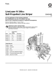
LineLazer IV 250SPS
Self-Propelled Line Striper
3A2593B
EN
For the application of line striping materials.
For professional use only.
For outdoor use only.
Not for use in hazardous locations or explosive atmospheres.
Maximum Operating Speed: 10 mph (16 kph)
Maximum Operating Pressure: 3300 psi (22.8 MPa, 228 bar)
IMPORTANT SAFETY INSTRUCTIONS
Read all warnings and instructions in this manual
and the engine manual. Save these instructions.
Related Manuals:
3A2090
Operation
3A2598
Parts
311254
Gun
309277
Pump
312307
Auto-Layout Applications Methods
ti24910a
Table of Contents
Models . . . . . . . . . . . . . . . . . . . . . . . . . . . . . . . . . . . 3
Warnings . . . . . . . . . . . . . . . . . . . . . . . . . . . . . . . . . 4
Component Identification . . . . . . . . . . . . . . . . . . . . 7
Component Identification (Controls) . . . . . . . . . . . 8
Grounding Procedure
(For Flammable Materials Only) . . . . . . . . . . . 9
Pressure Relief Procedure . . . . . . . . . . . . . . . . . . . 9
Ground Drive Belt Replacement . . . . . . . . . . . . . 10
Removal . . . . . . . . . . . . . . . . . . . . . . . . . . . . . . 10
Installation . . . . . . . . . . . . . . . . . . . . . . . . . . . . . 10
Oil Reservoir Belt Replacement . . . . . . . . . . . . . . 11
Removal . . . . . . . . . . . . . . . . . . . . . . . . . . . . . . 11
Installation . . . . . . . . . . . . . . . . . . . . . . . . . . . . . 11
Hydraulic System Purging . . . . . . . . . . . . . . . . . . 12
Ground Drive Pump Replacement . . . . . . . . . . . . 13
Removal . . . . . . . . . . . . . . . . . . . . . . . . . . . . . . 13
Installation . . . . . . . . . . . . . . . . . . . . . . . . . . . . . 13
Oil Reservoir Pump Replacement . . . . . . . . . . . . 14
Removal . . . . . . . . . . . . . . . . . . . . . . . . . . . . . . 14
Installation . . . . . . . . . . . . . . . . . . . . . . . . . . . . . 14
Hydraulic Gun Manifold Replacement . . . . . . . . . 16
Removal . . . . . . . . . . . . . . . . . . . . . . . . . . . . . . 16
Installation . . . . . . . . . . . . . . . . . . . . . . . . . . . . . 17
Paint Pump Replacement . . . . . . . . . . . . . . . . . . . 18
Removal . . . . . . . . . . . . . . . . . . . . . . . . . . . . . . 18
Installation . . . . . . . . . . . . . . . . . . . . . . . . . . . . . 18
Hydraulic Motor Replacement . . . . . . . . . . . . . . . 19
Removal . . . . . . . . . . . . . . . . . . . . . . . . . . . . . . 19
Installation . . . . . . . . . . . . . . . . . . . . . . . . . . . . . 19
Clutch Replacement . . . . . . . . . . . . . . . . . . . . . . . 20
Removal . . . . . . . . . . . . . . . . . . . . . . . . . . . . . . 20
Installation . . . . . . . . . . . . . . . . . . . . . . . . . . . . . 21
Engine Replacement . . . . . . . . . . . . . . . . . . . . . . . 22
Removal . . . . . . . . . . . . . . . . . . . . . . . . . . . . . . 22
Installation . . . . . . . . . . . . . . . . . . . . . . . . . . . . . 23
2
Touch-Pad Replacement . . . . . . . . . . . . . . . . . . . . 24
Removal . . . . . . . . . . . . . . . . . . . . . . . . . . . . . . 24
Installation . . . . . . . . . . . . . . . . . . . . . . . . . . . . . 24
Control Board, Toggle Switches and Display
Replacement . . . . . . . . . . . . . . . . . . . . . . . . . . 25
Removal . . . . . . . . . . . . . . . . . . . . . . . . . . . . . . 25
Installation . . . . . . . . . . . . . . . . . . . . . . . . . . . . . 26
Battery Replacement . . . . . . . . . . . . . . . . . . . . . . . 28
Removal . . . . . . . . . . . . . . . . . . . . . . . . . . . . . . 28
Installation . . . . . . . . . . . . . . . . . . . . . . . . . . . . . 28
Fuse Replacement . . . . . . . . . . . . . . . . . . . . . . . . . 29
Forward/Reverse Cable Replacement . . . . . . . . . 30
Removal . . . . . . . . . . . . . . . . . . . . . . . . . . . . . . 30
Installation . . . . . . . . . . . . . . . . . . . . . . . . . . . . . 31
Steering Cable Replacement . . . . . . . . . . . . . . . . 32
Removal . . . . . . . . . . . . . . . . . . . . . . . . . . . . . . 32
Installation . . . . . . . . . . . . . . . . . . . . . . . . . . . . . 33
Front Wheel Replacement . . . . . . . . . . . . . . . . . . . 34
Removal . . . . . . . . . . . . . . . . . . . . . . . . . . . . . . 34
Installation . . . . . . . . . . . . . . . . . . . . . . . . . . . . . 34
Parking Brake Service . . . . . . . . . . . . . . . . . . . . . . 35
Removal . . . . . . . . . . . . . . . . . . . . . . . . . . . . . . 35
Installation . . . . . . . . . . . . . . . . . . . . . . . . . . . . . 35
Rear Wheel and Wheel Motors . . . . . . . . . . . . . . . 36
Rear Wheel Removal . . . . . . . . . . . . . . . . . . . . 36
Rear Wheel Installation . . . . . . . . . . . . . . . . . . . 36
Wheel Motor Removal . . . . . . . . . . . . . . . . . . . . 36
Wheel Motor Installation . . . . . . . . . . . . . . . . . . 37
Wheel Sensor Replacement . . . . . . . . . . . . . . . 37
Troubleshooting . . . . . . . . . . . . . . . . . . . . . . . . . . . 39
General . . . . . . . . . . . . . . . . . . . . . . . . . . . . . . . 39
Wiring Diagram . . . . . . . . . . . . . . . . . . . . . . . . . . . 43
Wiring Parts List . . . . . . . . . . . . . . . . . . . . . . . . 44
Hydraulic Diagram . . . . . . . . . . . . . . . . . . . . . . . . . 45
Hydraulic Parts List . . . . . . . . . . . . . . . . . . . . . . 46
Graco Standard Warranty . . . . . . . . . . . . . . . . . . . 49
3A2593B Repair
Models
Models
Model
Guns
Pressurized Bead System
24F307
2
No
LLIV 250SPS (North America, Latin America, Asia Pacific)
24K960
1
No
LLIV 250SPS (Latin America, Asia Pacific)
24K961
1
No
LLIV 250SPS (Europe)
24K962
2
No
LLIV 250SPS (Europe)
24M608
1
No
FieldLazer G400 (North America)
16V470
1
Yes, 1 Tank
LLIV 250 SPS (Latin America, Asia Pacific)
16V471
1
Yes, 1 Tank
LLIV 250 SPS (Europe)
16V473
2
Yes, 1 Tank
LLIV 250 SPS (North America, Latin America, Asia Pacific)
16V474
2
Yes, 1 Tank
LLIV 250 SPS (Europe)
24U561
2
Yes, 2 Tanks
LLIV 250 SPS (North America, Latin America, Asia Pacific)
3A2593B Repair
Description
3
Warnings
Warnings
The following warnings are for the setup, use, grounding, maintenance, and repair of this equipment. The exclamation point symbol alerts you to a general warning and the hazard symbols refer to procedure-specific risks. When
these symbols appear in the body of this manual or on warning labels, refer back to these Warnings. Product-specific
hazard symbols and warnings not covered in this section may appear throughout the body of this manual where
applicable.
WARNING
TRAFFIC HAZARD
Being struck by other vehicles may result in serious injury or death.
• Do not operate in traffic.
• Use appropriate traffic control in all traffic areas.
• Follow local highway and transportation regulations for traffic control (for example: Manual on Uniform
Traffic Control Devices, U.S. Department of Transportation).
FIRE AND EXPLOSION HAZARD
Flammable fumes, such as solvent and paint fumes, in work area can ignite or explode. To help prevent fire
and explosion:
• Use equipment only in well ventilated area.
• Do not fill fuel tank while engine is running or hot; shut off engine and let it cool. Fuel is flammable and can
ignite or explode if spilled on hot surface.
• Keep work area free of debris, including solvent, rags and gasoline.
• Ground all equipment in the work area. See Grounding instructions.
• Use only grounded hoses.
• Hold gun firmly to side of grounded pail when triggering into pail. Do not use pail liners unless they are antistatic or conductive.
• Stop operation immediately if static sparking occurs or you feel a shock. Do not use equipment until you
identify and correct the problem.
• Keep a working fire extinguisher in the work area.
INJECTION HAZARD
High-pressure fluid from gun, hose leaks, or ruptured components will pierce skin. This may look like just a cut,
but it is a serious injury that can result in amputation. Get immediate surgical treatment.
• Do not spray without tip guard and trigger guard installed.
• Engage trigger lock when not spraying.
• Do not point gun at anyone or at any part of the body.
• Do not put your hand over the spray tip.
• Do not stop or deflect leaks with your hand, body, glove, or rag.
• Follow the Pressure Relief Procedure when you stop spraying and before cleaning, checking, or servicing equipment.
• Tighten all fluid connections before operating the equipment.
• Check hoses and couplings daily. Replace worn or damaged parts immediately.
CARBON MONOXIDE HAZARD
Exhaust contains poisonous carbon monoxide, which is colorless and odorless. Breathing carbon monoxide
can cause death.
• Do not operate in an enclosed area.
4
3A2593B Repair
Warnings
WARNING
PRESSURIZED ALUMINUM PARTS HAZARD
Use of fluids that are incompatible with aluminum in pressurized equipment can cause serious chemical reaction and equipment rupture. Failure to follow this warning can result in death, serious injury, or property damage.
• Do not use 1,1,1-trichloroethane, methylene chloride, other halogenated hydrocarbon solvents or fluids
containing such solvents.
• Many other fluids may contain chemicals that can react with aluminum. Contact your material supplier for
compatibility.
ENTANGLEMENT HAZARD
Rotating parts can cause serious injury.
• Keep clear of moving parts.
• Do not operate equipment with protective guards or covers removed.
• Do not wear loose clothing, jewelry or long hair while operating equipment.
• Equipment can start without warning. Before checking, moving, or servicing equipment, follow the Pressure Relief Procedure and disconnect all power sources.
MOVING PARTS HAZARD
Moving parts can pinch, cut or amputate fingers and other body parts.
• Keep clear of moving parts.
• Do not operate equipment with protective guards or covers removed.
• Pressurized equipment can start without warning. Before checking, moving, or servicing equipment, follow
the Pressure Relief Procedure and disconnect all power sources.
EQUIPMENT MISUSE HAZARD
Misuse can cause death or serious injury.
• Do not operate the unit when fatigued or under the influence of drugs or alcohol.
• Do not exceed the maximum working pressure or temperature rating of the lowest rated system component. See Technical Data in all equipment manuals.
• Use fluids and solvents that are compatible with equipment wetted parts. See Technical Data in all equipment manuals. Read fluid and solvent manufacturer’s warnings. For complete information about your
material, request MSDS from distributor or retailer.
• Do not leave the work area while equipment is energized or under pressure.
• Turn off all equipment and follow the Pressure Relief Procedure when equipment is not in use.
• Check equipment daily. Repair or replace worn or damaged parts immediately with genuine manufacturer’s replacement parts only.
• Do not alter or modify equipment. Alterations or modifications may void agency approvals and create
safety hazards.
• Make sure all equipment is rated and approved for the environment in which you are using it.
• Use equipment only for its intended purpose. Call your distributor for information.
• Route hoses and cables away from traffic areas, sharp edges, moving parts, and hot surfaces.
• Do not kink or over bend hoses or use hoses to pull equipment.
• Keep children and animals away from work area.
• Comply with all applicable safety regulations.
• Do not carry passengers.
• Check work area for reduced overhead clearance (e.g. doorways, tree branches, parking ramp ceilings)
and avoid contacting them.
3A2593B Repair
5
Warnings
WARNING
BATTERY SAFETY
The battery may leak, explode, cause burns, or cause an explosion if mishandled.
• Only use the battery type specified for use with the equipment. See Technical Data.
• Battery maintenance must only be performed or supervised by personnel knowledgeable of batteries and
the required precautions. Keep unauthorized personnel away from battery.
• Do not dispose of battery in fire. The battery is capable of exploding.
• Follow local ordinances and/or regulations for disposal.
• Do not open or mutilate the battery. Released electrolyte has been known to be harmful to the skin and
eyes and to be toxic.
• Remove watches, rings, or other metal objects.
• Only use tools with insulated handles. Do not lay tools or metal parts on top of battery.
BURN HAZARD
Equipment surfaces and fluid that’s heated can become very hot during operation. To avoid severe burns:
• Do not touch hot fluid or equipment.
PERSONAL PROTECTIVE EQUIPMENT
Wear appropriate protective equipment when in the work area to help prevent serious injury, including eye
injury, hearing loss, inhalation of toxic fumes, and burns. This protective equipment includes but is not limited
to:
• Protective eyewear, and hearing protection.
• Respirators, protective clothing, and gloves as recommended by the fluid and solvent manufacturer.
CALIFORNIA PROPOSITION 65
The engine exhaust from this product contains a chemical known to the State of California to cause
cancer, birth defects or other reproductive harm.
This product contains a chemical known to the State of California to cause cancer, birth defects or other
reproductive harm. Wash hands after handling.
6
3A2593B Repair
Component Identification
Component Identification
1.
16.
15.
14.
11.
17.
2.
13.
12.
10.
3.
F
OF
ON
9.
8.
4.
5.
7.
6.
ti24911a
ti15841a
Operator Platform
10
Engine ON/OFF Switch
2
Paint Filter
11
Hydraulic Fill Cap / Dipstick
3
Prime / Drain Valve
12
Hydraulic Oil Filter
4
Displacement Pump
13
Paint Hopper (25 gallon / 95 liter)
5
Rear Gun Arm Mount
14
Handle Bar Height Adjustment Knob
6
Serial Label
15
Engine Recoil Handle
7
Gun Trigger Safety
16
Brake
8
Wheel Motor Bypass Valve
17
Steering Handle
9
Straight Line Adjuster
1
3A2593B Repair
7
Component Identification (Controls)
Component Identification (Controls)
5.
4.
3.
6.
2.
7.
1.
1
on
off
2
8.
1
9.
2
10.
11.
ti18719a
8
1
Hydraulic Pump Valve
2
Gun Trigger Control
3
Forward / Reverse Lever
4
Display
5
Engine Throttle
6
Engine Choke
7
Gun 1 Selector
8
Gun 2 Selector
9
Engine Kill / Main Power Switch
10
12V Accessory Jack
11
Pressure Control
3A2593B Repair
Grounding Procedure (For Flammable Materials Only)
Grounding Procedure
Pressure Relief Procedure
(For Flammable Materials Only)
This equipment must be grounded to reduce the risk
of static sparking. Static sparking can cause fumes to
ignite or explode. Grounding provides an escape
wire for the electric current.
1. Position striper so that the tires are not on pavement.
2. Ground sprayer with grounding clamp. Grounding
clamp must attach to grounded object (e.g. metal
sign post).
Follow the Pressure Relief Procedure whenever
you see this symbol.
This equipment stays pressurized until pressure is
manually relieved. To help prevent serious injury
from pressurized fluid, such as skin injection,
splashing fluid and moving parts, follow the Pressure
Relief Procedure when you stop spraying and before
cleaning, checking, or servicing the equipment.
1. Perform Grounding Procedure if using flammable
materials.
2. Set pump valve OFF. Turn engine OFF.
ti6740a
ti3306a
3. Turn pressure control to lowest setting. Trigger gun
to relieve pressure.
ti3305a
PAINT
ti3441a
4. Engage gun trigger safety. Turn prime valve down.
ti6473a
ti3324a
3A2593B Repair
9
Ground Drive Belt Replacement
Ground Drive Belt
Replacement
Installation
1. Install belt onto pulleys.
Removal
ti19134a
1. Loosen four screws and remove belt cover.
2. Tighten tensioning bolt to move two pulleys apart
and tighten belt to proper tension (see table).
ti19132a
ti19128a
Ground Drive Belt
Tension Recommendations
2. Loosen two hold-down bolts.
Tension
53 +/- 2 Lbf (236 +/- 9 N)
Frequency
167 +/- 3 Hz
Tension
45 +/- 2 Lbf (200 +/- 9 N)
Used Belt
Frequency
155 +/- 3 Hz
Gates Sonic Tension Meter
Settings: M = MASS = 85 g/m
W = # of belts = 1
S = Span = 157 mm
New Belt
ti19130a
3. Loosen tension bolt to bring two pulleys closer
together to create slack in the belt.
3. Install mounting plate and tighten two hold-down
bolts.
ti19131a
ti19129a
4. Remove belt.
4. Replace belt cover and tighten four screws.
ti19133a
ti19128a
10
3A2593B Repair
Oil Reservoir Belt Replacement
Oil Reservoir Belt
Replacement
Installation
1. Replace belt.
Removal
ti19149a
NOTE: Ground drive belt must be removed before oil
reservoir belt can be replaced (see page 10).
2. Tighten two adjustment bolts evenly and maintain
belt alignment. Tighten belt to proper tension (see
table).
1. Loosen four hold-down bolts.
ti19147a
ti19150a
2. Loosen two adjustment bolts to bring pulleys closer
together to create slack in the belt.
Oil Reservoir Belt
Tension Recommendations
Tension
55 +/- 2 Lbf (245 +/- 9 N)
Frequency
114 +/- 2 Hz
Tension
48 +/- 2 Lbf (214 +/- 9 N)
Used Belt
Frequency
106 +/- 2 Hz
Gates Sonic Tension Meter
Settings: M = MASS = 85 g/m
W = # of belts = 1
S = Span = 236 mm
New Belt
ti19146a
3. Remove belt.
3. Tighten four hold-down bolts.
ti19148a
ti19151a
4. Install Ground Drive Belt and tighten to proper
tension (see page 10).
3A2593B Repair
11
Hydraulic System Purging
Hydraulic System
Purging
5. Turn on the Main Power Switch to engage clutch.
This equipment stays pressurized until pressure is
manually relieved. To help prevent serious injury
from pressurized fluid, such as skin injection,
splashing fluid and moving parts, follow the Pressure
Relief Procedure when you stop spraying and before
cleaning, checking, or servicing the equipment.
ti18552a
6. Slowly pull forward/reverse control lever in forward
and reverse directions 10 times.
Follow this procedure after replacing any hydraulic
component other than the hydraulic gun manifold which
is self-purging.
ti18718a
1. Set LineStriper on blocks so wheels are off ground.
ti18587a
NOTE: Both rear wheels should turn in the correct
direction. If one wheel is not turning, carefully
restrain the spinning wheel to purge out the wheel
that is not turning.
7. Turn the prime valve down and open the hydraulic
pump valve. Allow the paint pump to stroke 10 times
and then close the hydraulic pump valve.
2. Fill oil reservoir to “Full” range.
ti6473a
on
off
Full Range (cold)
ti3431a
3. Make sure drive wheel release is closed (+).
ti19669a
8. The hydraulic gun manifold is self-purging.
+
9. Turn engine off and check oil level. Top off to “Full”
range.
ti18576a
4. Start engine and run at low speed.
Full Range (cold)
ti3431
ti18562a
12
3A2593B Repair
Ground Drive Pump Replacement
Ground Drive Pump
Replacement
5. Remove nut (3) and disconnect tie rod (40) underneath pump (63).
6. Remove two mounting bolts (82) and washers (55)
to remove pump (63) from bracket.
Installation
This equipment stays pressurized until pressure is
manually relieved. To help prevent serious injury
from pressurized fluid, such as skin injection,
splashing fluid and moving parts, follow the Pressure
Relief Procedure when you stop spraying and before
cleaning, checking, or servicing the equipment.
1. Insert pump (63) into bracket (62) and install two
mounting bolts (82) and washers (55).
2. Install tie rod (40) with nut (3) to lever underneath
pump (63).
3. Connect all fittings and hoses to pump (63).
Removal
1. Remove Ground Drive Belt, page 10.
2. Use allen wrench to remove two set screws (71)
from pulley (64).
4. Install key (60) onto pump shaft and slide pulley (64)
onto shaft.
5. Align pulley to outer clutch groove and tighten two
set screws (71).
3. Slide pulley (64) off shaft and save key (60).
6. Install Ground Drive Belt and tighten to proper tension (see page 10).
4. Disconnect all fittings and hoses from pump (63).
7. Purge Hydraulic System, page 12.
NOTE: Oil will spill out of hoses. Have rags and
waste pail nearby.
71
60
63
71
64
62
3
55
ti19135a
82
40
3A2593B Repair
13
Oil Reservoir Pump Replacement
Oil Reservoir Pump
Replacement
This equipment stays pressurized until pressure is
manually relieved. To help prevent serious injury
from pressurized fluid, such as skin injection,
splashing fluid and moving parts, follow the Pressure
Relief Procedure when you stop spraying and before
cleaning, checking, or servicing the equipment.
6. Remove pulley from pump. Remove four screws
and pump from reservoir cover.
ti19672a
Installation
1. Install pump onto oil reservoir cover with four
screws.
Removal
1. Remove belt cover and Oil Reservoir Belt, page
11.
2. Remove oil filter and disconnect three hydraulic
hoses from oil reservoir.
ti19671a
ti24913a
ti19139a
3. Loosen nut and slide cable sleeve down to gain
access to cable set screw.
2. If hydraulic oil is contaminated in reservoir, drain
reservoir and remove contamination. Install oil
reservoir cover with eight screws to the oil reservoir
base.
ti19144a
4. Remove set screw and cable.
ti24914a
3. Install pulley on pump shaft and maintain belt alignment to inner groove of the clutch pulley. Tighten
two pulley screws.
ti19142a
5. Remove eight screws and oil reservoir cover with
pump.
ti24914a
14
ti19670a
3A2593B Repair
Oil Reservoir Pump Replacement
4. Turn pressure control knob clockwise until seated.
7. Slide cable sleeve up and tighten screw.
ti19145a
8. Connect three hydraulic hoses to fittings on oil
reservoir. Replace oil filter.
ti23905a
5. Turn hydraulic pump pressure control clockwise
until seated then counterclockwise 1/6 turn.
ti23906a
ti24913a
ti19139a
ti23906a
9. Install and tension Oil Reservoir Belt (page 11)
and Ground Drive Belt (page 10).
6. Install cable and tighten set screws.
10. Purge hydraulic system, page 12.
ti19143a
3A2593B Repair
15
Hydraulic Gun Manifold Replacement
Hydraulic Gun Manifold
Replacement
6. Label wire harnesses GUN 1 and GUN 2. Disconnect two wire harnesses from solenoids.
Gun 2
Gun 1
Removal
ti19161a
1. Remove tank lid and siphon tube.
7. Label gun cables Gun 1 and Gun 2. Disconnect gun
cables from actuators.
Gun #
ti19159a
ti24916a
8. Use a needle-nose pliers to remove gun cables from
bracket.
ti24196a
2. Remove tank from unit.
3. Remove six screws from front shield.
ti19667a
9. Use wrench to disconnect manifold tubes by the
paint pump. NOTE: Oil will spill. Use a rag to contain the oil.
ti19163a
4. Remove front shield from unit.
5. Loosen four screws and remove pad.
ti19164a
16
ti19160a
3A2593B Repair
Hydraulic Gun Manifold Replacement
10. Disconnect manifold tubes at manifold.
11. Remove two mounting bolts and slide hydraulic
manifold down and out from unit.
4. Push Gun 1 and Gun 2 gun cables into bracket.
NOTE: Be sure to connect Gun 1 cable to the hole
in the bracket closest to center of sprayer.
5. Connect Gun 1 and Gun 2 cables to actuators.
ti19159a
ti19162a
6. Connect two wire harnesses to solenoids.
NOTE: Be sure to connect Gun 1 to coil closest to
center of sprayer.
Installation
Gun 2
1. Slide hydraulic manifold in and up into unit. Install
and tighten two mounting bolts.
Gun 1
ti19161a
7. Install pad and tighten four screws.
8. Install front shield to unit and tighten six screws.
ti19162a
2. Loosely install manifold tubes to manifold.
9. Install tank into unit and connect siphon tube.
NOTE: The hydraulic gun manifold is self-purging.
3. Loosely install manifold tubes by the paint pump.
Tighten four nuts.
ti19160a
3A2593B Repair
17
Paint Pump Replacement
Paint Pump Replacement
5. Use hammer to loosen pump jam nut (106).
6. Slide down retainer (104) and remove pin (105).
7. Unscrew and remove paint pump (107).
This equipment stays pressurized until pressure is
manually relieved. To help prevent serious injury
from pressurized fluid, such as skin injection,
splashing fluid and moving parts, follow the Pressure
Relief Procedure when you stop spraying and before
cleaning, checking, or servicing the equipment.
Installation
1. Extend pump rod out of pump (107).
2. Insert pump rod into hydraulic motor rod and install
pin (105) and retainer (104).
1. Perform Pressure Relief Procedure, page 9.
3. Thread pump (107) into hydraulic motor housing
until pump bottoms out. Unscrew pump one full turn
and orient pump outlet (approximately 45°) to clear
ball valve hose.
2. Disconnect suction tube (120).
4. Use hammer to tighten pump jam nut (106).
3. Disconnect hose (123) and fitting (95) from paint
pump (107).
5. Install guard (114) with screw (115) and nut (116).
Removal
6. Install fitting (95) and connect hose (123).
4. Remove screw (115), nut (116) and pump guard
(114).
115
7. Connect suction tube (120).
104
116
109
197
106
114
110
105
95
123
107
120
ti19138a
18
3A2593B Repair
Hydraulic Motor Replacement
Hydraulic Motor
Replacement
NOTICE
Use a screwdriver to lift pump piston up to gain
access to mounting bolts and avoid contact with piston. Contact with pump mounting bolts can scratch
and damage the pump piston.
This equipment stays pressurized until pressure is
manually relieved. To help prevent serious injury
from pressurized fluid, such as skin injection,
splashing fluid and moving parts, follow the Pressure
Relief Procedure when you stop spraying and before
cleaning, checking, or servicing the equipment.
Removal
6. Remove four mounting bolts (116) from hydraulic
motor and remove motor from sprayer.
Installation
1. Install hydraulic motor with four mounting bolts
(116).
NOTICE
1. Perform Pressure Relief Procedure, page 9.
2. Remove Paint Pump, page 18.
3. Disconnect fitting (108) above ball valve (109).
NOTE: Oil will spill out of hoses. Have rags and
waste pail nearby.
4. Disconnect hose (111) and fitting (193) from fitting
(196).
5. Disconnect pump counter (112) with 2 screws (113).
Use a screwdriver to lift pump piston up to gain
access to mounting bolts and avoid contact with piston. Contact with pump mounting bolts can scratch
and damage the pump piston.
2. Install pump counter (112) with two screws (113).
3. Connect hose (111) and fitting (193) to fitting (196).
4. Connect fitting (108) above ball valve (109).
5. Install Paint Pump, page 18.
6. Purge hydraulic system, page 12.
193
196
113
108
111
109
112
116
110
ti19688a
3A2593B Repair
19
Clutch Replacement
Clutch Replacement
7. Remove engine recoil starter and place a screwdriver through the recoil starter cup.
Removal
1. Remove Ground Drive Belt, page 10.
ti19696a
2. Remove Oil Reservoir Belt, page 11.
3. Remove two hold-down bolts for the ground drive
pump bracket.
ti19215a
4. Unscrew tensioning bolt from the ground drive
pump bracket.
ti19697a
8. Remove center bolt (59) and remove clutch (57).
57
ti19131a
58
5. Move ground drive pump assembly aside.
56
60
59
ti19214a
9. Disconnect clutch connector to main wire harness.
ti19213a
6. Remove three bolts (81) and pulley (61).
61
81
ti19212a
ti19216a
20
3A2593B Repair
Clutch Replacement
Installation
4. Install pulley (61) and torque three screws (81) to 10
ft-lb (13 N•m).
1. Install spacer (56) and key (60) onto crankshaft.
Slide clutch (57) onto crankshaft.
57
61
56
81
60
58
ti19216a
59
ti19214a
5. Install recoil starter onto engine.
2. Align clutch and wire in bracket.
ti19704a
6. Connect clutch to wire harness.
ti19211a
3. Install heavy washer (58) and bolt (59) onto crankshaft. Torque bolt to 45 +/- 5 ft-lb (61 +/- 7 N•m).
Use screwdriver in recoil starter cup to hold crankshaft.
ti19212a
7. Install ground drive pump assembly with tensioning
and two hold-down bolts.
58
59
ti19692a
ti19908a
8. Install and tension Oil Reservoir Belt (page 11)
and Ground Drive Belt (page 10).
3A2593B Repair
21
Engine Replacement
Engine Replacement
5. Disconnect choke cable.
Removal
1. Remove Clutch, see page 20.
ti19185a
2. Disconnect all wires from engine.
6. Tie knot in rope by recoil starter to prevent rope
from being pulled into recoil starter.
7. Take rope handle apart and untie knot in recoil
starter handle.
ti15307a
3. Remove air filter cover, element and base.
ti19188a
8. Pull rope through rope guide.
9. Remove four mounting bolts from engine.
ti19187a
10. Remove engine. NOTE: Engine voltage regulator is
located below engine mounting plate. Remove two
screws and disconnect wires.
ti19186a
4. Disconnect throttle cable.
ti19183a
ti19703a
22
3A2593B Repair
Engine Replacement
Installation
d. Tighten screw on hex-shaped pivot.
1. Install engine voltage regulator below engine
mounting plate with two screws. Connect regulator
to wire harness.
e. Verify proper operation of engine choke.
ti19686a
6. Install throttle cable.
a. Place speed lever to high speed.
b. Insert “Z” bend wire into hole furthest from pivot.
ti19706a
2. Install engine and tighten four mounting bolts and
nuts.
c.
Place cable sheathing under clamp and pull
cable against high speed stop screw.
d. Tighten screw on cable clamp.
e. Verify proper operation of speed lever.
ti19187a
3. Use compressed air to feed recoil starter rope
through rope guide.
ti19690a
7. Install air filter base, element and cover.
ti19708a
4. Feed rope through recoil starter handle and tie knot.
ti19186a
8. Connect three wires to engine.
1 in. (25 mm)
ti20066a
5. Install choke cable:
a. Make sure choke knob is pressed down.
b. Insert choke cable wire into hex-shaped pivot.
c.
Insert cable sheathing under cable clamp and
tighten screw.
3A2593B Repair
ti19668a
9. Install Clutch, see page 20.
10. Add gas and oil to engine (see Operation manual).
11. Start engine and verify high speed of 3600 rpm.
23
Touch-Pad Replacement
Touch-Pad Replacement
Removal
Installation
1. Remove six screws and control shroud.
1. Apply touch-pad to sheet metal.
2. Connect ribbon cable from touch-pad at display
board.
ti19098a
2. Disconnect ribbon cable from touch-pad at display
board.
ti19910a
3. Install control shroud with six screws.
ti19910a
3. Peel off touch-pad and remove adhesive from sheet
metal.
24
ti19098a
3A2593B Repair
Control Board, Toggle Switches and Display Replacement
Control Board, Toggle
Switches and Display
Replacement
7. Remove six screws and control shroud.
Removal
1. Remove Fuse to disconnect battery, page 29.
2. Remove tank lid and siphon tube.
ti19098a
8. Remove two screws and splash shield.
ti24916a
ti24916a
3. Remove tank from unit.
ti19701a
9. Remove two toggle switch nuts from control panel.
4. Use wrench to remove six screws from front shield.
ti19702a
ti19163a
10. Feed toggle switches through control panel.
5. Remove front shield from unit.
6. Remove four screws and remove pad.
ti20244a
ti19164a
3A2593B Repair
25
Control Board, Toggle Switches and Display Replacement
11. If replacing the toggle switches loosen two screws
holding the ferrite core. Disconnect cable and
remove toggle switch board.
ti20133a
13. If replacing control board, disconnect all wires from
control board. Remove eight mounting screws and
remove control board.
ti19198a
ti20135a
ti20136a
ti19199a
12. If replacing the display, remove two screws holding
the ferrite core to toggle switch bracket. Pull apart
ferrite core to remove from ribbon cable. Disconnect
display ribbon cable from control board. Disconnect
touchpad ribbon cable from display board. Remove
four screws holding display and remove display.
Installation
1. If replacing control board, install control board with
eight mounting screws.
ti20133a
ti19199a
ti20132a
2. Connect all wires to control board. See Wiring
Diagram, page 43.
ti19910a
ti19198a
ti20245a
3. If replacing display, install display with four screws.
Install touchpad ribbon cable to display board.
Install display ribbon cable to control board. Assemble ferrite core on ribbon cable. Install ferrite core to
toggle switch bracket with two screws.
4. If replacing toggle switches, install toggle switches
into toggle switch bracket. Make sure to place spacers between toggle switches and bracket. Connect
cable to toggle switch board.
26
3A2593B Repair
Control Board, Toggle Switches and Display Replacement
5. Feed toggle switches through control panel and
install two toggle switch nuts.
10. Install front shield and tighten six screws.
ti19691a
6. Install Fuse, see page 29. Check control, switches
and display.
ti19200a
11. Install tank, lid and siphon tube.
7. Install splash shield with two screws.
ti19705a
8. Install control shroud with six screws.
ti24917a
ti24917a
12. If control board was replaced, calibrate distance
sensor (see Operation manual).
ti19098a
9. Install pad and tighten four screws.
ti19171a
3A2593B Repair
27
Battery Replacement
Battery Replacement
Installation
1. Install battery.
NOTICE
To reduce the risk of shorting the battery, always
connect NEGATIVE (black wire) last.
Removal
1. Remove tank lid and siphon tube.
2. Connect red wire to positive (+) and black wire to
negative (-) posts of the battery.
ti24916a
ti24916a
2. Remove tank from unit.
3. Use wrench to remove six screws from front shield.
ti24920a
3. Install battery hold down strap.
ti19163a
4. Remove front shield from unit.
5. Remove hold down strap from battery.
ti24921a
4. Install front shield and use wrench to tighten six
screws into shield.
ti24918a
NOTICE
To reduce the risk of shorting the battery, always disconnect NEGATIVE (black wire) first.
ti19200a
5. Replace tank and install lid with siphon tube.
6. Disconnect two wires from battery.
ti24917a
ti24917a
ti24919a
ti24919a
7. Remove battery.
28
3A2593B Repair
Fuse Replacement
Fuse Replacement
1. Remove fuse cover.
2. Use needle-nose pliers to remove old fuse and
inspect it for open circuit.
3. If fuse is open, a wire has shorted to the frame or
auxiliary lighting requires too much power. Check
wiring or reduce auxiliary lighting before replacing
fuse.
4. Use needle-nose pliers to install new fuse.
5. Replace cover.
ti19209a
3A2593B Repair
29
Forward/Reverse Cable Replacement
Forward/Reverse Cable
Replacement
6. At the handlebar, remove locknut (3) and ball joint
(40) from handlebar forward/reverse lever. Remove
ball joint (40) from cable (148) and save if not
replacing. Loosen two nuts on cable (148) and
remove from bracket.
40
3
Removal
1. Remove tank lid and siphon tube.
148
ti19699a
ti24916a
7. At the ground drive pump, remove locknut (3) and
ball joint (40) from ground drive pump. Remove ball
joint from cable and save if not replacing. Loosen
two nuts on cable (148) and remove from bracket
(62).
ti24916a
2. Remove tank from unit.
3. Use wrench to remove six screws from front shield.
62
3
148
40
ti19163a
4. Remove front shield from unit.
5. Loosen four screws and remove belt cover.
ti19700a
8. Install new cable (148) as old cable is removed to
follow same route through frame.
ti19128a
30
3A2593B Repair
Forward/Reverse Cable Replacement
Installation
3. Install cable (148) into handlebar bracket and
tighten two nuts. Install ball joint (40) onto cable.
Install ball joint into handlebar forward/reverse lever
and tighten locknut (3).
1. Install new cable (148) by following same route as
old cable is being removed.
2. At ground drive pump bracket (62), install cable
(148) in bracket slot and tighten two nuts. Install ball
joint (40) onto cable and attach ball joint (40) to
ground drive pump with locknut (3).
40
3
148
62
3
148
40
ti19699a
4. Verify that the handlebar forward/reverse lever does
NOT touch handlebar grips. Adjust cable and ball
joints if needed.
5. Install belt cover and tighten four screws.
ti19700a
6. Install front shield onto unit.
7. Use wrench to tighten six screws into front shield.
8. Install tank onto unit.
9. Install siphon tube and tank lid.
3A2593B Repair
31
Steering Cable Replacement
Steering Cable
Replacement
7. Apply parking brake. Raise front wheel off the
ground and support frame on two jack stands.
Removal
1. Remove tank lid and siphon tube.
ti18550a
8. At the handlebar, remove locknut (3) and ball joint
(40) from handlebar. Remove ball joint (40) from
cable (48) and save if not replacing. Loosen two
nuts on cable (48) and remove from bracket.
3
40
ti24916a
ti24916a
48
2. Remove tank from unit.
3. Use wrench to remove six screws from front shield.
ti19695a
ti19163a
4. Remove front shield from unit.
9. On front wheel fork, remove locknut (3) and ball joint
(40) from fork. Remove ball joint (40) from cable
(48) and save if not replacing. Loosen two nuts on
cable (48) and remove from bracket.
5. Loosen four screws and remove pad.
48
40
3
ti19164a
6. Remove six screws and control shroud.
ti19698a
10. Note position of cable (48) and cut off all cable ties
that retain cable to frame. Install new cable as old
cable is removed to follow same route through
frame.
ti19098a
32
3A2593B Repair
Steering Cable Replacement
Installation
1. Install new cable (48) by following same route as old
cable is being removed.
5. Install ball joint (40) onto cable (48) and match
threads on other side of handlebar. Install ball joint
(40) into handlebar and tighten locknut (3).
3
2. At front wheel, adjust front nut on cable (48) to
match the threads on the other side of front fork.
Install cable (48) into frame bracket and tighten rear
nut.
40
48
Adjust to match
other side
of front fork
ti19685a
3. Install ball joint (40) onto cable (48) and match
threads on other side of front fork. Install ball joint
(40) into fork and tighten locknut (3).
48
40
ti19695a
6. Verify that handlebar is aligned straight with frame.
If misaligned, adjust nuts on cable (48) to straighten
handlebar to frame.
7. Verify that front wheel self-centers and that steering
is tight and responsive. Ball joint (40) should rotate
easily on the ball. If needed, remove ball joint from
fork and adjust ball joint on cable (48).
3
ti19698a
4. At handlebar, adjust front nut on cable (48) to match
threads on other side of handlebar. Install cable (48)
into bracket and tighten rear nut.
Adjust to match
other side
of handlebar
8. Install pad and tighten four screws.
9. Remove jack stands and test drive sprayer to check
steering. Adjust if needed. Install cable ties in locations noted in step 10 of Removal.
10. Verify straight line tracking and adjust if necessary
(see Operation manual).
ti19685a
11. Install control shroud and tighten six screws.
12. Install front shield onto unit.
13. Use wrench to tighten six screws into front shield.
14. Install tank onto unit.
15. Install siphon tube and tank lid.
3A2593B Repair
33
Front Wheel Replacement
Front Wheel Replacement
Installation
1. Insert two spacers (36) into wheel (35) and slide into
fork (34).
Removal
1. Apply parking brake. Raise front wheel off ground
and support frame on two jack stands.
34
39
37
36
ti20125a
ti19693a
36
2. Remove locknut (39) from axle bolt (37) and remove
axle bolt (37) from fork (34).
35
2. Insert axle bolt (37) through fork (34), spacers (36)
and wheel (35).
3. Tighten locknut (39) onto axle bolt (37).
NOTE: When properly tightened, the wheel should
not wobble to the left or right and should stop
coasting quickly.
34
4. Verify front tire pressure is 55-80 psi (380-550 kPa).
39
37
5. Remove jack stands and test drive sprayer to verify
straight line tracking. Adjust if necessary (see Operation manual).
36
ti20125a
36
35
3. Remove two spacers (36) and wheel (35) from fork
(34).
34
3A2593B Repair
Parking Brake Service
Parking Brake Service
Installation
1. Install lever (14) with pin (B) and clip (13).
Removal
2. Use screwdriver to install spring (15).
16
1. Remove tire, wheel hub, and fender. See Wheel
Motor Removal, page 36.
16
A
2. Remove clips (13) from three pins (A). Remove pins
and levers.
A
A
16
16
10
A
17
10
17
A
10
15
14
A
ti19684a
13
A
15
15
B
B
13
B
B
13
17
A
15
14
17
14
14
A
A
10
ti19684a
13
3. Use screwdriver to remove spring (15). Remove clip
(13) and pin (B).
3. Install levers (10, 16) with three pins (A) and clips
(13).
4. Install fender, wheel hub, and tire. See Wheel
Motor Installation, page 37.
5. Adjust screw (17) to hold tire when brake lever (16)
is depressed.
4. Replace damaged or worn parts.
3A2593B Repair
35
Rear Wheel and Wheel Motors
Rear Wheel and Wheel Motors
Wheel Motor Removal
1. Place jack under frame near wheel and raise jack.
Rear Wheel Removal
2. Remove four lug nuts (22) and wheel (16).
1. Set LineStriper on blocks so wheels are off ground.
16
22
ti18587a
2. Remove four lug nuts (22) and wheel (16).
ti18589a
3. Remove pin (56), castle nut (21b) and wheel hub
(22b). Wheel hub may require a wheel puller; not
supplied by Graco.
16
4
19
21a
6
5
79
22
112
22b
ti18589a
56
ti18584a
Rear Wheel Installation
21b
78
1. Replace wheel and install lug nuts. Alternately
tighten lug nuts opposite of each other.
4. Remove four bolts (78), lock nuts (79) and fender
(19).
2. Tilt LineStriper on side and remove blocks.
5. Remove screw (6) and distance sensor (4) with
clamp (5).
6. Disconnect two hydraulic hoses (112) from wheel
motor (21a) and remove wheel motor.
ti18588a
3. Inflate rear tires to 55 +/- 5 psi (380 +/- 34 kPa).
36
3A2593B Repair
Rear Wheel and Wheel Motors
Wheel Motor Installation
2. Remove tank from unit.
1. Connect two hydraulic hoses (112) to wheel motor
(21a) and insert wheel motor (21a) into frame (1).
3. Use wrench to remove six screws from front shield
and remove front shield from unit.
2. Install distance sensor (4) and clamp (5) with screw
(6).
6
5
4
19
79
21a
ti19163a
112
22b
56
ti18584a
21b
4. Place jack under frame near pump-side wheel and
raise jack.
5. Remove four lug nuts (22) and wheel (16).
16
78
3. Install wheel motor (21a) and fender (19) with four
bolts (78) and lock nuts (79).
ti18589a
22
4. Install wheel hub (22b), castle nut (21b), and pin
(56).
5. Install wheel (16) and four lug nuts (22). Alternately
tighten lug nuts opposite each other.
6. Disconnect wheel sensor connector from wire harness.
16
22
ti18589a
6. Purge hydraulic system. See Hydraulic System
Purging, page 12.
Wheel Sensor Replacement
ti19328a
7. Use wrench to remove screw (6), clamp (5), and
wheel sensor (4).
Removal
6
1. Remove tank lid and siphon tube.
ti24916a
3A2593B Repair
4
5
ti19099a
37
Rear Wheel and Wheel Motors
Installation
5. Install wheel (16) and four lug nuts (22).
1. Install wheel sensor (4) and clamp (5) with screw
(6).
16
6
22
5
4
ti18589a
6. Lower jack.
7. Install front shield with six screws.
ti19099a
2. Connect wheel sensor connector to wire harness.
ti19200a
ti19328a
8. Install tank and siphon tube.
3. Verify sensor is working by turning on the main
power switch and press SETUP to display the
MEASURE screen.
4. Press gun trigger control button and rotate hub by
hand exactly three turns.
ti18564a
ti19329a
NOTE: Sensor is working properly if the measure
display reads 12.3 to 12.7 ft (3.75 to 3.87 m).
38
ti24917a
9. Calibrate sprayer. See operation manual.
3A2593B Repair
Troubleshooting
Troubleshooting
General
Problem
Engine pulls hard
Engine will not start
High engine speed at no load
Machine will not drive
Engine operates, but
displacement pump does
not operate
3A2593B Repair
Cause
Excessive hydraulic load. Main power switch
is on.
Solution
Turn main power switch OFF.
Engine is out of gas.
Refill gas tank. See engine manual.
Fuel shut-off lever is OFF.
Move fuel shut-off lever to ON position.
Engine switch is OFF.
Turn engine switch ON.
Engine oil level is low.
Check oil level and add oil if necessary. See engine
manual.
Engine is cold.
Use engine choke.
Spark plug cable is disconnected or damaged.
Connect spark plug cable or replace spark plug cable.
Main power switch is stuck in engine stop
position.
Replace main power switch.
Oil is seeping into combustion chamber.
Remove spark plug. Pull starter 2 to 4 times. Clean or
replace spark plug. Start engine. Keep sprayer upright
to avoid oil seepage.
Improperly adjusted high speed setting.
Reset high speed to 3600 - 3700 engine rpm at no load.
Worn engine governor.
Adjust or replace engine governor.
Main power switch is not turned ON.
Turn main power switch ON.
Hydrostatic drive is not engaged.
Close wheel motor bypass valve to engage drive.
Drive cable is disconnected or broken.
Reconnect or replace cable.
Clutch wire harness is disconnected or broken.
Reconnect or replace harness as
necessary.
Clutch does not work.
Replace clutch.
Ground drive belt is worn or broken.
Adjust or replace ground drive belt.
Ground Drive Pump is worn or not working.
Replace ground drive pump.
Wheel motor(s) worn or not working.
Replace wheel motor.
Main power switch is OFF.
Turn main power switch ON.
Pump valve is OFF.
Turn pump valve ON.
Pressure setting is too low.
Turn pressure adjusting knob clockwise to increase
pressure. See operation manual.
Prime/drain valve is closed and system
is pressurized.
Open prime/drain valve.
Hydraulic fluid too low.
Shut off sprayer. Add fluid*.
Oil reservoir belt is worn, broken, or off
the pulley.
Replace oil reservoir belt. See page 11.
Tip is clogged.
Reverse tip to clean. See manual 311254.
Displacement pump piston rod is stuck due to
dried paint.
Repair pump. See manual 309277.
Hydraulic motor not shifting.
Set pump valve OFF. Turn pressure down. Turn engine
OFF. Pry rod up or down until hydraulic motor shifts.
39
Troubleshooting
Problem
Displacement pump operates, but
output is low on upstroke
Displacement pump operates but output
is low on downstroke and/or on both
sides
Pump is difficult to prime
Low stall or run pressure shown on
display
Excessive paint leakage into throat
packing nut
Fluid is spitting from gun
40
Cause
Solution
Piston ball is not seating.
Service piston ball. See manual 309277.
Piston packings are worn or damaged.
Replace packings. See manual 309277.
Suction tube strainer is clogged.
Clean strainer.
Suction tube air leak.
Tighten suction tube.
Pressure setting is too low.
Increase pressure. See operation manual.
Fluid filter or tip is clogged or dirty.
Clean filter and tip. See operation manual or gun
manual 311254.
Engine speed is too low.
Increase throttle setting. See operation manual.
Intake valve ball is packed with material or is
not seating properly.
Clean intake valve. See manual 309277.
Pump packings are worn or damaged.
Replace pump packings. See manual 309277.
Large pressure drop in hose with heavy
materials.
Use larger diameter hose and/or reduce overall length
of hose. Use of more than 100 ft x 1/4 in. hose significantly reduces performance of sprayer. Use 3/8 in.
hose for optimum performance.
Oil reservoir hydraulic filter is dirty or clogged.
Change hydraulic filter and hydraulic oil.
Intake line to pump inlet is not tight.
Tighten intake line to pump inlet.
Hydraulic motor is worn or damaged.
Bring sprayer to Graco distributor for repair.
Suction tube strainer is clogged.
Clean strainer
Suction tube air leak.
Tighten suction tube
Drain line to paint hopper is clogged.
Clean drain line
Intake valve is leaking.
Clean intake valve. Be sure ball seat is not nicked or
worn and that ball seats well. Reassemble valve.
Pump packings are worn.
Replace pump packings. See manual 309277.
Paint is too thick.
Thin the paint according to supplier recommendations.
Engine speed is too high.
Decrease throttle setting before priming pump. See
operation manual.
New pump or new packings
Pump break-in period takes up to 100 gallons
of material.
Faulty transducer
Replace transducer.
Throat packing nut is loose.
Remove throat packing nut spacer. Tighten throat
packing nut just enough to stop leakage.
Throat packings are worn or damaged.
Replace packings. See manual 309277.
Displacement rod is worn or damaged.
Replace rod. See manual 309277.
Air in pump or hose
Check and tighten all fluid connections. Reprime pump.
See operation manual.
Tip is partially clogged.
Clear tip. See manual 311254.
Fluid supply is low or empty.
Refill fluid supply. Prime pump. See operation manual.
Check fluid supply often to prevent running pump dry.
3A2593B Repair
Troubleshooting
Problem
Excessive leakage around hydraulic
motor piston rod wiper
Sprayer overheats
Excessive hydraulic pump noise
Display does not turn on
Gallon (liter) counter not
adding fluid volume
Distance not adding properly
(MEASURE mode will be inaccurate
and speed will be wrong)
Mils not calculating
Pressure control knob does not rotate
Pressure control knob rotates freely
with no pressure change
Gun does not trigger
Gun triggering is slow
3A2593B Repair
Cause
Solution
Piston rod seal worn or damaged.
Replace hydraulic motor piston rod wiper and seal.
Paint buildup on hydraulic components
Clean hydraulic components.
Hydraulic oil level is low
Fill with hydraulic oil. See operation manual.
Low hydraulic fluid level
Shut off sprayer. Add fluid*.
Pulleys loose on hydraulic pumps
Remove belt guard. Check and tighten loose pulley.
Main power switch is not turned on
Turn main power switch on.
Main fuse is blown
Replace fuse. See Fuse Replacement, page 29.
Cable between display and board disconnected
or damaged
Reconnect or replace touch pad.
Display board failure
Replace display board.
Fluid pressure not high enough
Must be over 800 psi (55 bar) for counter to add.
Broken or disconnected wire
Check wires and connections. Replace any broken
wires.
Missing or damaged magnet
Reposition or replace magnet.
Bad sensor
Replace sensor. See Hydraulic Motor Replacement,
page 19.
Machine not calibrated
Perform calibration procedure. See Operation manual.
Rear tire pressure is too low or too high
Adjust tire pressure to 55 +/- 5 psi (380 +/- 34 kPa).
Gear teeth missing or damaged
(pump side only)
Replace distance gear/wheel hub.
Distance sensor is loose or broken
Reconnect or replace sensor.
Distance sensor
See “Distance not adding properly”.
Gallon counter
See “Gallon (liter) counter not adding fluid volume”.
Bad or damaged control board
Replace control board.
Knob is jammed
Pull back cover where remote cable connects to
hydraulic pump and turn counter-clockwise (ccw) until
free.
Set screw at hydraulic pump connection is
loose
Remove cover and tighten set screw.
Reassemble cover.
Remote cable is broken or disconnected
Replace or reconnect cable.
Main power switch is not turned ON
Turn main power switch ON.
Gun selector switch is OFF
Turn gun selector switch ON.
Display is in AUTO MODE and speed is less
than 0.7 mph (1.1 kph)
Increase ground speed to be greater than 0.7 mph
(1.1 kph).
System pressure is too low
Increase fluid pressure up to at least
1000 psi.
Gun cable is disconnected or broken
Reconnect or replace cable.
Gun trigger control switch is disconnected or
broken
Reconnect or replace gun trigger control switch.
Disconnected or broken wires from control
board to solenoid
Reconnect or replace wires.
Gun cable is pinched or kinked
Change gun cable routing or replace cable.
System pressure is too low
Increase fluid pressure up to at least 1000 psi.
41
Troubleshooting
Problem
Cause
Solution
AUTO Mode
Line spacing is not accurate
Gun does not trigger
Wrong line pattern loaded
Reload the correct pattern.
Machine not calibrated
Perform calibration routine (see Operation manual).
See Gun Does Not Trigger, page 41.
PARKING LAYOUT Mode
Gun does not apply dots
Gun selector switch is OFF
Turn gun selector switch ON.
Dot size setting is too small
Increase dot size.
Pressure is too low
Increase pressure to 1000 psi.
* Use only Graco approved hydraulic fluid 169236 (5 gallons / 18.9 liter) or 207428 (1 gallon / 3.8 liter)
42
3A2593B Repair
3A2593B Repair
223
112
4
189
238
237
224
TO GROUND LUG
BLACK
RED
GUN 1
GUN 2
225
189a
391
221
187
214c
214e
150
TO GROUND LUG
214b
TO GROUND LUG
222
214f
214t
134
WHITE
RED
RED
RED
BLACK
253
TO ENGINE
YELLOW
WHITE
BLACK
RED
BLACK
220
RED
BLACK
RED
RED
YELLOW
BLACK
BLACK
BLACK
54a
YELLOW
214h
TO GROUND LUG
57
54
Wiring Diagram
Wiring Diagram
ti19065a
43
Wiring Diagram
Wiring Parts List
Ref.
4
54
Part
Description
15K357 SENSOR, distance
24N501 KIT, repair, engine, GX270
(includes 54a)
54a 24N502 VOTLAGE REGULATOR
57
125877 CLUTCH, electric, LL250
112 119720 SWITCH, reed w/connector
134 24L904 CONTROL, handlebar
150 115753 BATTERY, 33 AH, sealed
187 237686 WIRE, ground assembly w/ clamp
189 16N513 MANIFOLD, hydraulic, two piston
189a 24N577 COIL, solenoid, hydraulic, manifold
(included in 189)
214b 24N565 KIT, repair, control board
214c 24N564 KIT, repair, display board
44
Qty
.
1
1
1
1
1
1
1
1
1
2
1
1
Qty
.
Ref.
Part
Description
214e
214f
214h
214t
220
221
222
223
224
225
237
238
253
391
16N374
24N566
126078
16P019
16N407
16N542
16N541
16N540
16N539
16N543
126095
126096
114956
24N516
SWITCH, membrane
KIT, repair, switch board
SWITCH, rocker, dpdt
HARNESS, switch board
HARNESS, wire, LL250
WIRE, positive battery
WIRE, negative battery
HARNESS, light connection
HARNESS, sensor adapter
HARNESS, wire, hydraulic actuator
HOLDER, fuse
FUSE, 30A
TERMINAL, wire tap, insulated
KIT, repair, transducer
1
1
1
1
1
1
1
1
1
2
1
1
1
1
3A2593B Repair
3A2593B Repair
196
3YY
366
198
197
109
108
370
372
371
366
189C
194
189A
189B
193
2
189
111
110
166
22
191
63
309
333
190
327
166
2
3XX
320
ti24923a
3XX
Hydraulic Diagram
Hydraulic Diagram
45
Hydraulic Diagram
Hydraulic Parts List
Ref.
Part
Description
2
22
63
108
109
110
111
166
189
125929
16M271
247930
117328
117441
287175
287176
16M276
16N513
MOTOR, wheel
HOSE, coupled, assembly, LL250
KIT, repair, hydraulic pump
FITTING, nipple, straight
VALVE, ball
KIT, repair, hose, hydraulic s
KIT, repair, hose, hydraulic r
HOSE, coupled, feed line, LL250
MANIFOLD, hydraulic, two piston
(includes two 189b and two 189c)
COIL, solenoid, hydraulic, manifold
KIT, repair, solenoid
(includes 189a)
KIT, repair, actuator piston
FITTING, long elbow, hydraulic
FITTING, 90 degree, w/adjustable
TUBE, supply, hydraulic
189a 24N577
189b 24N490
189c
190
191
193
46
24N491
124941
116829
24M625
Qty
.
Qty
.
Ref.
Part
Description
2
2
1
1
1
1
1
2
1
194
196
197
198
309
320
327
333
350
24M626
126082
126080
126081
16M160
287179
246173
122970
116829
1
1
351
366
370
371
372
16P776
117607
100139
15F519
119841
TUBE, supply, hydraulic
FITTING, tee, #8 x #8 x #6 JIC
FITTING, tee, street
FITTING, nipple, 3/8-18 x #6 JIC
COVER, reservoir, LL250, painted
KIT, repair, pump, 200HS
KIT, repair, oil filter
FITTING, hydraulic
FITTING, 90 degree, w/adjustable
o-ring
TUBE, supply, hydraulic
FITTING, elbow std thd
PLUG, pipe
TUBE, hydraulic, supply
FITTING, tee, branch
1
1
1
1
1
1
1
1
1
1
1
1
2
1
2
1
1
1
3A2593B Repair
Notes
Notes
3A2593B Repair
47
Graco Standard Warranty
Graco warrants all equipment referenced in this document which is manufactured by Graco and bearing its name to be free from defects in
material and workmanship on the date of sale to the original purchaser for use. With the exception of any special, extended, or limited warranty
published by Graco, Graco will, for a period of twelve months from the date of sale, repair or replace any part of the equipment determined by
Graco to be defective. This warranty applies only when the equipment is installed, operated and maintained in accordance with Graco’s written
recommendations.
This warranty does not cover, and Graco shall not be liable for general wear and tear, or any malfunction, damage or wear caused by faulty
installation, misapplication, abrasion, corrosion, inadequate or improper maintenance, negligence, accident, tampering, or substitution of
non-Graco component parts. Nor shall Graco be liable for malfunction, damage or wear caused by the incompatibility of Graco equipment with
structures, accessories, equipment or materials not supplied by Graco, or the improper design, manufacture, installation, operation or
maintenance of structures, accessories, equipment or materials not supplied by Graco.
This warranty is conditioned upon the prepaid return of the equipment claimed to be defective to an authorized Graco distributor for verification of
the claimed defect. If the claimed defect is verified, Graco will repair or replace free of charge any defective parts. The equipment will be returned
to the original purchaser transportation prepaid. If inspection of the equipment does not disclose any defect in material or workmanship, repairs
will be made at a reasonable charge, which charges may include the costs of parts, labor, and transportation.
THIS WARRANTY IS EXCLUSIVE, AND IS IN LIEU OF ANY OTHER WARRANTIES, EXPRESS OR IMPLIED, INCLUDING BUT NOT
LIMITED TO WARRANTY OF MERCHANTABILITY OR WARRANTY OF FITNESS FOR A PARTICULAR PURPOSE.
Graco’s sole obligation and buyer’s sole remedy for any breach of warranty shall be as set forth above. The buyer agrees that no other remedy
(including, but not limited to, incidental or consequential damages for lost profits, lost sales, injury to person or property, or any other incidental or
consequential loss) shall be available. Any action for breach of warranty must be brought within two (2) years of the date of sale.
GRACO MAKES NO WARRANTY, AND DISCLAIMS ALL IMPLIED WARRANTIES OF MERCHANTABILITY AND FITNESS FOR A
PARTICULAR PURPOSE, IN CONNECTION WITH ACCESSORIES, EQUIPMENT, MATERIALS OR COMPONENTS SOLD BUT NOT
MANUFACTURED BY GRACO. These items sold, but not manufactured by Graco (such as electric motors, switches, hose, etc.), are subject to
the warranty, if any, of their manufacturer. Graco will provide purchaser with reasonable assistance in making any claim for breach of these
warranties.
In no event will Graco be liable for indirect, incidental, special or consequential damages resulting from Graco supplying equipment hereunder, or
the furnishing, performance, or use of any products or other goods sold hereto, whether due to a breach of contract, breach of warranty, the
negligence of Graco, or otherwise.
FOR GRACO CANADA CUSTOMERS
The Parties acknowledge that they have required that the present document, as well as all documents, notices and legal proceedings entered into,
given or instituted pursuant hereto or relating directly or indirectly hereto, be drawn up in English. Les parties reconnaissent avoir convenu que la
rédaction du présente document sera en Anglais, ainsi que tous documents, avis et procédures judiciaires exécutés, donnés ou intentés, à la suite
de ou en rapport, directement ou indirectement, avec les procédures concernées.
Graco Information
For the latest information about Graco products, visit www.graco.com.
For patent information, see www.graco.com/patents.
TO PLACE AN ORDER, contact your Graco distributor or call 1-800-690-2894 to identify the nearest distributor.
All written and visual data contained in this document reflects the latest product information available at the time of publication.
Graco reserves the right to make changes at any time without notice.
For patent information, see www.graco.com/patents.
Original instructions. This manual contains English. MM 3A2593
Graco Headquarters: Minneapolis
International Offices: Belgium, China, Japan, Korea
GRACO INC. P.O. BOX 1441 MINNEAPOLIS, MN 55440-1441
Copyright 2010, Graco Inc. is registered to ISO 9001
www.graco.com
Revision B, November 2014