1
Repair-Parts
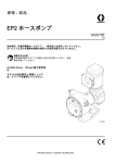
EP2 Hose Pump
3A1940G
EN
Electric--powered hose pump for use in fluid transfer and metering applications. For professional use
Electric
only.
Not approved for use in explosive atmospheres or hazardous locations.
Important Safety Instructions
Read all warnings and instructions in this manual. Save these
instructions.
125 psi (0.9 MPa, 9 bar) Maximum Fluid
Working Pressure
See page 2 for model part numbers and
information.
PROVEN QUALITY. LEADING TECHNOLOGY.
Contents
Models............................................................... 2
EP2 Hose Pump Assembly........................... 18
Bare Pump Assembly................................... 20
Pump Matrix ................................................ 22
Pump Kit Matrix ........................................... 24
Variable Frequency Drives (VFD).................. 27
Warnings ........................................................... 3
Troubleshooting.................................................. 6
Repair................................................................ 8
Before You Start .......................................... 8
Disassembly ................................................ 8
Reassembly ................................................ 12
Notes................................................................. 28
Notes................................................................. 17
Graco Standard Warranty.................................... 30
Technical Data ................................................... 29
Parts.................................................................. 18
Models
Pump Model
Hose ID Size
(mm)
Reference
EP2006
6
See Model EP2006 Pumps, page 22 for a complete list of
pump part numbers and descriptive information.
EP2013
13
See Model EP2013 Pumps, page 23 for a complete list of
pump part numbers and descriptive information.
2
3A1940G
Warnings
Warnings
The following warnings are for the setup, use, grounding, maintenance and repair of this equipment. The
exclamation point symbol alerts you to a general warning and the hazard symbol refers to procedure-specific
risks. When these symbols appear in the body of this manual or on warning labels, refer back to these
Warnings. Product-specific hazard symbols and warnings not covered in this section may appear throughout
the body of this manual where applicable.
WARNING
FIRE AND EXPLOSION HAZARD
Flammable fumes, such as solvent and paint fumes, in work area can ignite or explode. To help
prevent fire and explosion:
• Use equipment only in well ventilated area.
• Eliminate all ignition sources; such as pilot lights, cigarettes, portable electric lamps, and
plastic drop cloths (potential static arc).
• Keep work area free of debris, including solvent, rags and gasoline.
• Do not plug or unplug power cords, or turn power or light switches on or off when flammable
fumes are present.
• Ground all equipment in the work area. See Grounding instructions.
• Use only grounded hoses.
• Hold gun firmly to side of grounded pail when triggering into pail.
• If there is static sparking or you feel a shock, stop operation immediately. Do not use
equipment until you identify and correct the problem.
• Keep a working fire extinguisher in the work area.
ELECTRIC SHOCK HAZARD
This equipment must be grounded. Improper grounding, setup, or usage of the system can
cause electric shock.
• Turn off and disconnect power at main switch before disconnecting any cables and before
servicing or installing equipment.
• Connect only to grounded power source.
• All electrical wiring must be done by a qualified electrician and comply with all local codes
and regulations.
MOVING PARTS HAZARD
Moving parts can pinch, cut or amputate fingers and other body parts.
• Keep clear of moving parts.
• Do not operate equipment with protective guards or covers removed.
• Pressurized equipment can start without warning. Before checking, moving, or servicing
equipment, follow the Pressure Relief Procedure and disconnect all power sources.
3A1940G
3
Warnings
WARNING
ENTANGLEMENT HAZARD
Rotating parts can cause serious injury.
•
•
•
•
Keep clear of moving parts.
Do not operate equipment with protective guards or covers removed.
Do not wear loose clothing, jewelry or long hair while operating equipment.
Equipment can start without warning. Before checking, moving or servicing equipment, follow
the Pressure Relief Procedure and disconnect all power sources.
TOXIC FLUID OR FUMES
Toxic fluids or fumes can cause serious injury or death if splashed in the eyes or on skin,
inhaled, or swallowed.
• Read MSDSs to know the specific hazards of the fluids you are using.
• Store hazardous fluid in approved containers, and dispose of it according to applicable
guidelines.
PERSONAL PROTECTIVE EQUIPMENT
You must wear appropriate protective equipment when operating, servicing, or when in the
operating area of the equipment to help protect you from serious injury, including eye injury,
hearing loss, inhalation of toxic fumes, and burns. This equipment includes but is not limited to:
• Protective eyewear, and hearing protection.
• Respirators, protective clothing, and gloves as recommended by the fluid and solvent
manufacturer.
PRESSURIZED EQUIPMENT HAZARD
Fluid from the equipment leaks, or ruptured components can splash in the eyes or on skin
and cause serious injury.
• Follow the Pressure Relief Procedure when you stop spraying/dispensing and before
cleaning, checking, or servicing equipment.
• Tighten all fluid connections before operating the equipment.
• Check hoses, tubes, and couplings daily. Replace worn or damaged parts immediately.
4
3A1940G
Warnings
WARNING
EQUIPMENT MISUSE HAZARD
Misuse can cause death or serious injury.
• Do not operate the unit when fatigued or under the influence of drugs or alcohol.
• Do not exceed the maximum working pressure or temperature rating of the lowest rated
system component. See Technical Data in all equipment manuals.
• Use fluids and solvents that are compatible with equipment wetted parts. See Technical Data
in all equipment manuals. Read fluid and solvent manufacturer’s warnings. For complete
information about your material, request MSDS from distributor or retailer.
• Do not leave the work area while equipment is energized or under pressure.
• Turn off all equipment and follow the Pressure Relief Procedure when equipment is not in use.
• Check equipment daily. Repair or replace worn or damaged parts immediately with genuine
manufacturer’s replacement parts only.
• Do not alter or modify equipment.
• Use equipment only for its intended purpose. Call your distributor for information.
• Route hoses and cables away from traffic areas, sharp edges, moving parts, and hot surfaces.
• Do not kink or over bend hoses or use hoses to pull equipment.
• Keep children and animals away from work area.
• Comply with all applicable safety regulations.
3A1940G
5
Troubleshooting
Troubleshooting
NOTE: Check all possible remedies before disassembling the pump.
Problem
Cause
Solution
Hammering in piping.
Inlet or outlet pipe diameters too
small.
Increase pipe size or add pulsation
dampeners.
High pump speed.
Reduce speed of pump.
Inlet or outlet connections not
properly anchored.
Secure piping.
High inlet or outlet pressures.
Add pulsation dampeners.
Low lubricant level.
Add hose lube to the proper level.
Improper lubricant.
Use only Graco hose lube for low
temperature operation.
Pumped fluid temperature too
high.
Consult your Graco distributor for
maximum temperature limits of
your pump.
High pump speed/pump
undersized.
Reduce the pump speed or switch
to a larger pump.
Blocked outlet line.
Clear any obstructions in the outlet
line.
Narrowed pipe diameter due to
settled solids.
Determine if solids have settled
in piping and flush/remove as
required.
Viscosity or specific gravity of
pumped fluid too high.
Consult your Graco distributor for
suitable operating conditions for
your pump.
Failed hose.
Check to see if the hose has failed.
If so, replace with a new hose and
lubricant.
Blocked inlet line.
Clear any obstructions in the inlet
line.
Inlet line too long or too small.
Try to locate the pump as near
to the fluid source as possible.
Oversize the inlet piping when
possible.
Viscosity or specific gravity of
pumped fluid too high.
Consult your Graco distributor for
suitable operating conditions for
your pump.
Failed hose.
Check to see if the hose has failed.
If so, replace with a new hose and
lubricant.
High pump temperature.
High outlet pressure.
Low inlet pressure.
Low flow.
6
3A1940G
Troubleshooting
Problem
Cause
Solution
Poor hose life.
Chemical incompatibility.
Consult your Graco distributor to
see if you have the correct hose
for your application.
Normal wear.
The hose may have failed due to
normal wear. Replace as required.
Failure due to pulsations.
If your pump is equipped with a
pulsation dampener, adjust its
pressure. If you do not have a
dampener, consult your Graco
distributor.
Too high outlet pressure.
Check items listed in “High outlet
pressure.” Running the pump
against a closed valve, even for a
short amount of time, may damage
hose.
Settled solids in hose.
Flush the pump and hose prior to
turning the pump off.
Hose lube leaking from front cover.
Cover bolts over-tightened.
Refer to torque specifications in
Install the Front Cover, page 16.
Hose lube leaking from hose
clamps.
Pump housing overfilled. Check
hose lube level and adjust as
necessary.
Pump was operated against a
closed outlet valve or blocked line.
Replace hose. Check pressure
relief system. Check that valves
are open. Clear any blockages.
Lubricant leaks.
Hose failed because it wrapped
around roller.
3A1940G
7
Repair
Repair
Before You Start
Disassembly
Drain the Oil
1. Hold a pail under the drain plug (17) and unscrew
the plug to drain the lubricating oil. Dispose of
the oil properly. Take care, as the oil may be
contaminated by the pumped fluid.
1. Flush the pump.
2. Remove the vent plug (15) and flush the pump
housing with a compatible solvent.
2. Relieve the pressure.
3. Disconnect power to the pump.
4. Make sure the pump is electrically isolated.
Unexpected operation of the pump can cause
serious injury. Remove the fan cover only after
the motor has been locked out.
Figure 1 Pump Drain and Vent
Remove the Front Cover
1. Unscrew the socket head cap screws (14) and
washers (13) that hold the front cover (12),
removing the top screw and washer last. Take
the cover off the pump. See Figure 5, page 11.
2. Remove the front cover gasket (11).
3. Inspect and clean the cover (12), then set aside.
8
3A1940G
Repair
Remove the Hose
1. See Figure 5, page 11. Remove the screws
holding the motor fan cover (FC). Turn the fan by
hand until the roller (102) stops at the bottom of
the pump housing (1) in the 6 o’clock position.
NOTE: Low RPM pumps and high ratio
gearboxes may require many turns of the motor
fan to move the roller to the 6 o’clock position.
2. Remove the four screws (115) from the barbed
fitting (105) on the inlet and outlet ports of the
pump.
6. Remove one barbed fitting (105) from the hose
(103).
7. Grasp the hose (103) from the inside of the pump
housing (1) and pull it into the housing. The
center of the hose will still be held by the roller in
the 6 o’clock position.
8. Remove the second barb assembly as described
above.
9. Turn the motor by hand until the roller (102) is not
compressing the hose (103). This will be near
the 9 o’clock or 3 o’clock position.
3. Gently pull the barbed fittings (105) away from
the pump housing (1) so the hose extends about
2–3 in. (51–76 mm) out of the pump.
4. If possible, ensure that the hose clamps (104)
are positioned with the clamp portion at the top.
Cut through the clamp with a hack saw or rotary
tool. Be careful not to damage the hose (103) or
the pump housing (1).
Figure 4 Roller in 9 O’Clock Position
10. Pull the other end of the hose into the pump
housing (1).
Figure 2 Cut the Clamp
11. Remove and safely discard the used hose, per
your facility’s waste disposal policy.
5. Using a screwdriver, remove the clamp, then
remove the band.
Figure 3 Remove the Clamp
3A1940G
9
Repair
Remove the Roller
1. Using external snap ring pliers, remove the roller
retaining ring (8) from the front of the eccentric
shaft (7).
2. Pull the roller (102) off the shaft. It should slide
off easily.
3. Inspect the inside and outside diameter of the
roller (102), and replace it if worn or damaged.
Figure 5 Remove the Hose and Roller
10
3A1940G
Repair
Remove the Eccentric Shaft
1. Using a flat head screw driver, remove the outer
u-cup seal (4).
1. Using external snap ring pliers, remove the
eccentric shaft retaining ring (8) from the motor
output shaft (2).
2. Remove the eccentric shaft (7) from the motor
output shaft. Be sure to retain the eccentric shaft
key (6).
NOTE: You may need to use a puller to
disengage the eccentric shaft from the motor
output shaft.
2. Using internal snap ring pliers, remove the
retaining ring (3) from the pump housing (1).
3. Remove the four screws (109) and washers (108)
holding the gearbox and motor assembly (107)
to the pump housing (1). Remove the gearbox
and motor assembly to allow access to the inner
u-cup seal (5). Be sure to retain the motor output
shaft key (106).
NOTE: For motor and gearbox repair information,
contact SEW-Eurodrive.
Remove the Motor Output Shaft
NOTE: The motor output shaft is held in place with
a retaining ring (3) located behind the outer u-cup
seal (4). The outer seal must be removed before
removing the retaining ring. This seal will likely be
damaged when removed since it is held in place by
a tight press fit.
4. Remove the inner u-cup seal (5). This seal will
likely be damaged when removed since it is held
in place by a tight press fit.
5. Tap the gearbox end of the shaft (2) with a rubber
mallet to drive the shaft out through the front of
the pump housing (1).
107
109
1
5
106
2
6
3
108
4
7
8
Figure 6 Remove the Eccentric Shaft and Motor Output Shaft
3A1940G
11
Repair
Reassembly
Clean and Inspect All Parts
NOTICE
Use only genuine Graco replacement parts.
Non-standard parts will void your warranty and
may damage your equipment.
2. Coat the outer races of the shaft bearings and
the inner diameter of the bearing bore with light
lubricating oil. Make sure there is no dirt or debris
on either the bearings or the bearing bore.
3. Insert the shaft (2) into the pump housing (1) from
the front, making sure that the bearings engage
the bearing bore flush and straight. Tap the roller
end of the shaft with a rubber mallet until the
shaft is firmly seated in the pump housing.
• Discard all used seals, gaskets and worn parts.
NOTICE
• Ensure that all new and existing parts are clean
and undamaged.
Do not force the shaft and bearings into the
pump housing. This may cause damage to the
bearings or the housing.
• Thoroughly clean all parts with a compatible
solvent and inspect for damage or wear. Replace
all gaskets, washers, worn parts and hardware as
necessary.
• Inspect the inner diameter of the pump roller. If the
surface has been worn, replace the roller.
• Inspect the bearings on the motor output shaft (2).
If the bearings are worn, replace the shaft.
• Inspect the shaft and bearing bore in the pump
housing (1). Ensure it is round, without grooves or
other signs of wear, and free of dirt, filings, or other
debris. A dirty or damaged bearing bore will greatly
reduce the life of the bearings.
• Inspect all metal parts for signs of wear or cracks.
Replace all worn parts.
NOTICE
The pump housing is aluminum. To help prevent
galling, blow out the threads with compressed air
before installing any fittings or fasteners.
Install the Motor Output Shaft
4. Install the bearing retaining ring (3) in front of the
outer bearing.
Install the Seals
1. Press a new inner u-cup seal (5) onto the gearbox
end of the shaft (2) and into the bore at the rear
of the pump housing (1). The lips of the u-cup
must face into the pump housing. See Figure 7.
2. Grease the pump with NLGI #2 type grease.
Remove the plug (18) from the pump housing
and replace it with a zerk fitting. Add grease until
it passes through the outer bearing of the shaft.
This provides a visual reference of the proper
amount of grease. Do not over-grease. Remove
the zerk fitting and reinstall the plug (18).
3. Press a new outer u-cup seal (4) onto the pump
end of the shaft (2) and into the bore at the front
of the pump housing (1). The lips of the u-cup
must face toward the shaft bearings.
4. Make sure that the shaft rotates smoothly.
1. Inspect the bearings and make sure that all rotate
freely and are seated against the shoulder of the
shaft (2). See Figure 6.
12
3A1940G
Repair
Figure 7 Install the Motor Output Shaft and Eccentric Shaft
Key for Figure 7
Note
Description
1
2
3
Lips of the u-cup (4) must face toward the shaft bearings.
Lips of the u-cup (5) must face into the pump housing.
Lubricate with hose lube.
Install the Motor and Gearbox
1. Lubricate the motor output shaft (2) and the
keyway with an anti-seize compound.
2. Slide the eccentric shaft (7) over the end of
the motor output shaft (2). Install the key (6).
The eccentric and the key should slide easily
together.
2. The gearbox is manufactured with a hollow
bore. Remove the plastic cap on the back of the
gearbox to help with alignment of the shaft.
3. Secure the eccentric shaft (7) with the eccentric
shaft retaining ring (8).
3. Slide the motor and gearbox assembly (107) onto
the shaft (2). Typically the assembly is mounted
with the motor above the gearbox. Install the key
(106). Secure to the pump housing (1) with the
four screws (109) and washers (108).
NOTE: The roller size is typically marked on the
roller. Verify that you have the correctly sized roller.
Install the Eccentric Shaft
1. Ensure that the keyway on the motor output shaft
(2) is facing up. It may be necessary to turn the
motor fan by hand to position the shaft.
3A1940G
Install the Roller
1. Lubricate the eccentric shaft (7) with hose lube.
Slide the roller (102) onto the shaft. The roller
should fit onto the shaft snugly with minimal
radial movement. See Figure 8.
2. Install the roller retaining ring (8). Verify that the
roller (102) turns freely on the shaft (7).
13
Repair
Figure 8 Install the Roller, Hose, and Front Cover
Key for Figure 8
Note
Description
4
5
14
Torque to 115 in-lb (13.0 N•m).
Torque to 25 in-lb (2.8 N•m).
3A1940G
Repair
Install the Hose
5. Cut the excess band, then flatten the end with a
rubber mallet.
1. Move the roller (102) by turning the motor fan
until the roller reaches the 6 o’clock position.
Figure 11 Flatten the Band
Figure 9 Roller in 6 O’Clock Position
6. Install the screws (115) and torque to 115 in-lb
(13.0 N•m).
2. Install one end of the hose (103) through the
rear port of the pump housing on the left hand
side when looking at it from the front. Extend
the hose 2-3 in. (51–76 mm) beyond the pump
housing (1).
7. Loop the hose (103) 360 degrees and pass the
other end through the front port on the right hand
side of the pump housing (1). Assemble the
barbed fitting (105) and clamp (104) as explained
in steps 3–6.
3. Slide the hose clamp (104) over the hose and
install the barbed fitting (105).
8. Turn the roller (102) to the 12 o’clock position
and push the hose into the pump housing. Use a
rubber mallet if the hose is difficult to seat.
4. Position the hose clamp about 1/4 in. (6 mm)
from the end of the hose. Using the 24L497
Clamping Tool, tighten the clamp to secure the
hose onto the barbed fitting.
9. Return the roller (102) to the 6 o’clock position,
compressing the hose. It is critical that the roller
is at the bottom of the pump to ensure the correct
capacity of hose lube. Reinstall the motor fan
cover.
NOTICE
The roller must be returned to the 6 o’clock
position before installing the front cover.
Failure to do so will result in overfilling of the
pump with hose lube.
Figure 10 Tighten the Clamp
3A1940G
15
Repair
Install the Front Cover
from the cover or the clamp area. Pre-measuring
the correct amount will help prevent overfilling.
1. Scrape all debris from the gasket mating surfaces
on the front cover (12) and the pump housing
(1), then clean with acetone or brake cleaner to
remove any residue. This is critical to ensure a
leak-free assembly.
NOTE: The pump housing and front cover must
be free of dirt, debris and residue to ensure a
leak-free seal.
2. Place a bead of compatible sealant on the gasket
surface of the front cover (12), to hold the gasket
in place during assembly.
NOTE: The hole pattern of the front cover (12),
gasket (11), and housing are asymmetric. This
ensures that the gasket and cover go on in only
one direction.
3. Line up the holes in the gasket (11) with the holes
in the cover (12) before placing the gasket on the
sealant bead. Place the gasket on the cover.
4. Line up the front cover and gasket with the pump
housing (1) by placing a socket head cap screw
(14) and washer (13) in the top hole and screwing
it into the pump housing (1).
5. Install the remaining front cover screws (14) and
washers (13). Torque the screws oppositely to
25 in-lb (2.8 N•m).
NOTE: Do not over-tighten the front cover
screws. This will cause the gasket to deform and
the pump to leak.
Lubricate the Pump
1. Wrap the drain plug (17) threads with PTFE tape
and install the plug.
2. Using a funnel, fill the pump housing with hose
lube through the vent port. The pump will require
approximately 8 oz (250 ml).
NOTE: Do not overfill. Overfilling the pump
housing with hose lube will increase pressure
in the pump housing, causing hose lube to leak
16
Figure 12 Lubricate through Vent Port (15)
3. Wrap the vent plug (15) threads with PTFE tape
and screw it into the vent port carefully.
NOTE: Higher operating speeds provide more
vigorous lubrication, which may cause splashing of
oil. When operating at a speed of 85 RPM or greater,
reduce the amount of hose lube as shown in the
table below.
Operating Speed (RPM) Reduction in Oil
0–84
Use quantity
recommended in step 2.
85–104
Use 70% of
recommended quantity
105–114
Use 60% of
recommended quantity
115 and above
Use 50% of
recommended quantity
3A1940G
Notes
Notes
3A1940G
17
Parts
Parts
EP2 Hose Pump Assembly
EP2006 and EP2013 Pumps, Series A
Includes items 101–119
18
3A1940G
Parts
Ref.
No.
Part No.
Description
Qty
Ref.
No.
101
24L887
ASSEMBLY, pump;
see Bare Pump
Assembly, page 20.
1
107
102
24K562
ROLLER KIT; for
EP2006; includes
one of item 8 (page
21)
1
ROLLER KIT; for
EP2013; includes
one of item 8 (page
21)
1
24K564
103
See Pump
Matrix,
page 22
HOSE KIT; includes
two hose clamps
(104)
1
104
24M116
KIT, hose clamp;
package of 10
1
105
See Pump
Matrix,
page 22
BARBED FITTING
KIT; kit includes one
barbed fitting, one
clamp (104), and four
screws (115)
2
KEY, motor shaft
1
106
---
uHose lube is also available in a 1 gallon (3.8 liter)
Part No.
Description
Qty
MOTOR and GEARBOX ASSEMBLY
(see Pump Matrix,
page 22, for the motor and gearbox used
on your pump)
1
24L982
0.5 HP; 51.30 gear
ratio; EP2006
24L983
0.75 HP; 35.10 gear
ratio; EP2013
24L985
0.33 HP; 157.43 gear
ratio; EP2006 and
EP2013
108
---
WASHER, split lock;
M6
4
109
---
SCREW, cap, hex hd;
M6 x 16 mm
4
115
---
SCREW, socket hd;
M4 x 12 mm
8
119u
24K692
HOSE LUBE;
glycerin; 1 quart
(0.95 liter); not shown
1
Parts labeled --- are not available separately.
bottle. Order Part No. 24K694.
3A1940G
19
Parts
Bare Pump Assembly
Model 24L887 Pump Assembly, Series A
Includes items 1–23
20
3A1940G
Parts
Ref.
No.
Part No.
Description
Qty
Ref.
No.
Part No.
Description
Qty
1
---
HOUSING, pump
1
11
24K572
GASKET KIT
1
2
24K574
SHAFT KIT, output,
motor; includes items
3, 4, 5, 6, 8, 18, and
grease zerk fitting
1
12
24K571
COVER KIT; includes
items 11, 13, 14, 15,
17, and 28
1
13
---
WASHER, flat; no. 8
6
3
---
RING, retaining,
bearing
1
14
---
SCREW, cap, socket
hd; M4 x 16 mm
6
4
---
SEAL, u-cup, outer
1
15
---
VENT, breather plug
1
5
---
SEAL, u-cup, inner
1
17
---
PLUG, drain; 1/4 npt
2
6
---
KEY, eccentric shaft
1
18
---
24K573
ECCENTRIC SHAFT
KIT; includes items 6
and 8
1
PLUG, pipe, headless;
1/8 npt
1
7
23
16K630
LABEL, warning; all
models
1
RING, retaining,
eccentric shaft
2
28
---
SIGHTGLASS, 3/4 npt
1
8
---
▲
▲Replacement Danger and Warning labels, tags,
Parts labeled --- are not available separately.
and cards are available at no cost.
3A1940G
21
Parts
Pump Matrix
Model EP2006 Pumps
With 6 mm ID Hose and Roller Installed
Pump Part
No.
Pump
Series
Hose Kit
(Ref. 103)
Hose Inner
Material
Hose
Stripe
Color
Barbed
Fitting Kit
(Ref. 105)
Barbed
Fitting
Material
Motor and
Gearbox
(Ref. 107)
24L100
B
24K483
EPDM
Blue
24K565
SST
24L985
24L101
B
24K483
EPDM
Blue
24K566
Hastelloy
24L985
24L104
B
24K482
Natural
Rubber
None
24K565
SST
24L985
24L105
B
24K487
CSM
Orange
24K565
SST
24L985
24L106
B
24K487
CSM
Orange
24K566
Hastelloy
24L985
24L107
B
24K484
Nitrile
Yellow
24K565
SST
24L985
24L108
B
24K484
Nitrile
Yellow
24K566
Hastelloy
24L985
24L114
B
24K483
EPDM
Blue
24K565
SST
24L982
24L115
B
24K483
EPDM
Blue
24K566
Hastelloy
24L982
24L118
B
24K482
Natural
Rubber
None
24K565
SST
24L982
24L119
B
24K487
CSM
Orange
24K565
SST
24L982
24L120
B
24K487
CSM
Orange
24K566
Hastelloy
24L982
24L121
B
24K484
Nitrile
Yellow
24K565
SST
24L982
24L122
B
24K484
Nitrile
Yellow
24K566
Hastelloy
24L982
24L128
B
24K483
EPDM
Blue
24K565
SST
24L984
24L129
B
24K483
EPDM
Blue
24K566
Hastelloy
24L984
24L132
B
24K482
Natural
Rubber
None
24K565
SST
24L984
24M735
A
24K483
EPDM
Blue
24K565
SST
None
24M736
A
24K483
EPDM
Blue
24K566
Hastelloy
None
24M739
A
24K482
Natural
Rubber
None
24K565
SST
None
24M740
A
24K487
CSM
Orange
24K565
SST
None
24M741
A
24K487
CSM
Orange
24K566
Hastelloy
None
24M742
A
24K484
Nitrile
Yellow
24K565
SST
None
24M743
A
24K484
Nitrile
Yellow
24K566
Hastelloy
None
24W549
A
24K487
CSM
Orange
24V970
PVDF
24L982
24W550
A
24K487
CSM
Orange
24V970
PVDF
24L985
24W551
A
24K487
CSM
Orange
24V970
PVDF
None
* Food grade hose inner material is white in color.
22
3A1940G
Parts
Model EP2013 Pumps
With 13 mm ID Hose and Roller Installed
Pump Part
No.
Pump
Series
Hose Kit
(Ref. 103)
Hose Inner
Material
Hose
Stripe
Color
Barbed
Fitting Kit
(Ref. 105)
Barbed
Fitting
Material
Motor and
Gearbox
(Ref. 107)
24L184
B
24K503
EPDM
Blue
24K569
SST
24L985
24L185
B
24K503
EPDM
Blue
24K570
Hastelloy
24L985
24L188
B
24K502
Natural
Rubber
None
24K569
SST
24L985
24L189
B
24K507
CSM
Orange
24K569
SST
24L985
24L190
B
24K507
CSM
Orange
24K570
Hastelloy
24L985
24L191
B
24K504
Nitrile
Yellow
24K569
SST
24L985
24L192
B
24K504
Nitrile
Yellow
24K570
Hastelloy
24L985
24L198
B
24K503
EPDM
Blue
24K569
SST
24L983
24L199
B
24K503
EPDM
Blue
24K570
Hastelloy
24L983
24L202
B
24K502
Natural
Rubber
None
24K569
SST
24L983
24L203
B
24K507
CSM
Orange
24K569
SST
24L983
24L204
B
24K507
CSM
Orange
24K570
Hastelloy
24L983
24L205
B
24K504
Nitrile
Yellow
24K569
SST
24L983
24L206
B
24K504
Nitrile
Yellow
24K570
Hastelloy
24L983
24L212
B
24K503
EPDM
Blue
24K569
SST
24L984
24L213
B
24K503
EPDM
Blue
24K570
Hastelloy
24L984
24L216
B
24K502
Natural
Rubber
None
24K569
SST
24L984
24M763
A
24K503
EPDM
Blue
24K569
SST
None
24M764
A
24K503
EPDM
Blue
24K570
Hastelloy
None
24M767
A
24K502
Natural
Rubber
None
24K569
SST
None
24M768
A
24K507
CSM
Orange
24K569
SST
None
24M769
A
24K507
CSM
Orange
24K570
Hastelloy
None
24M770
A
24K504
Nitrile
Yellow
24K569
SST
None
24M771
A
24K504
Nitrile
Yellow
24K570
Hastelloy
None
24W552
A
24K507
CSM
Orange
24V971
PVDF
24L983
24W553
A
24K507
CSM
Orange
24V971
PVDF
24L985
24W554
A
24K507
CSM
Orange
24V971
PVDF
None
* Food grade hose inner material is white in color.
3A1940G
23
Parts
Pump Kit Matrix
Model EP2006 Pump Kits
With 6 mm ID Hose (installed) and Roller (not installed)
Pump
Part No.
Roller Kit
(Ref. 102)
Hose Kit
(Ref. 103)
Hose Inner
Material
Hose Stripe
Color
Barbed
Fitting Kit
(Ref. 105)
Barbed
Fitting
Material
Motor and
Gearbox
(Ref. 107)
24L370
24K562
24K483
EPDM
Blue
24K565
SST
24L985
24L371
24K562
24K483
EPDM
Blue
24K566
Hastelloy
24L985
24L374
24K562
24K482
Natural
Rubber
None
24K565
SST
24L985
24L375
24K562
24K487
CSM
Orange
24K565
SST
24L985
24L376
24K562
24K487
CSM
Orange
24K566
Hastelloy
24L985
24L377
24K562
24K484
Nitrile
Yellow
24K565
SST
24L985
24L378
24K562
24K484
Nitrile
Yellow
24K566
Hastelloy
24L985
24L384
24K562
24K483
EPDM
Blue
24K565
SST
24L982
24L385
24K562
24K483
EPDM
Blue
24K566
Hastelloy
24L982
24L388
24K562
24K482
Natural
Rubber
None
24K565
SST
24L982
24L389
24K562
24K487
CSM
Orange
24K565
SST
24L982
24L390
24K562
24K487
CSM
Orange
24K566
Hastelloy
24L982
24L391
24K562
24K484
Nitrile
Yellow
24K565
SST
24L982
24L392
24K562
24K484
Nitrile
Yellow
24K566
Hastelloy
24L982
24L398
24K562
24K483
EPDM
Blue
24K565
SST
24L984
24L399
24K562
24K483
EPDM
Blue
24K566
Hastelloy
24L984
24L402
24K562
24K482
Natural
Rubber
None
24K565
SST
24L984
24L403
24K562
24K487
CSM
Orange
24K565
SST
24L984
24L404
24K562
24K487
CSM
Orange
24K566
Hastelloy
24L984
24L405
24K562
24K484
Nitrile
Yellow
24K565
SST
24L984
24L406
24K562
24K484
Nitrile
Yellow
24K566
Hastelloy
24L984
24N020
24K562
24K483
EPDM
Blue
24K565
SST
None
24N021
24K562
24K483
EPDM
Blue
24K566
Hastelloy
None
24N024
24K562
24K482
Natural
Rubber
None
24K565
SST
None
24N025
24K562
24K487
CSM
Orange
24K565
SST
None
24N026
24K562
24K487
CSM
Orange
24K566
Hastelloy
None
24N027
24K562
24K484
Nitrile
Yellow
24K565
SST
None
24N028
24K562
24K484
Nitrile
Yellow
24K566
Hastelloy
None
* Food grade hose inner material is white in color.
24
3A1940G
Parts
Model EP2013 Pump Kits
With 13 mm ID Hose (installed) and Roller (not installed)
Pump
Part No.
Roller Kit
(Ref. 102)
Hose Kit
(Ref. 103)
Hose Inner
Material
Hose Stripe
Color
Barbed
Fitting Kit
(Ref. 105)
Barbed
Fitting
Material
Motor and
Gearbox
(Ref. 107)
24L454
24K564
24K503
EPDM
Blue
24K569
SST
24L985
24L455
24K564
24K503
EPDM
Blue
24K570
Hastelloy
24L985
24L458
24K564
24K502
Natural
Rubber
None
24K569
SST
24L985
24L459
24K564
24K507
CSM
Orange
24K569
SST
24L985
24L460
24K564
24K507
CSM
Orange
24K570
Hastelloy
24L985
24L461
24K564
24K504
Nitrile
Yellow
24K569
SST
24L985
24L462
24K564
24K504
Nitrile
Yellow
24K570
Hastelloy
24L985
24L468
24K564
24K503
EPDM
Blue
24K569
SST
24L983
24L469
24K564
24K503
EPDM
Blue
24K570
Hastelloy
24L983
24L472
24K564
24K502
Natural
Rubber
None
24K569
SST
24L983
24L473
24K564
24K507
CSM
Orange
24K569
SST
24L983
24L474
24K564
24K507
CSM
Orange
24K570
Hastelloy
24L983
24L475
24K564
24K504
Nitrile
Yellow
24K569
SST
24L983
24L476
24K564
24K504
Nitrile
Yellow
24K570
Hastelloy
24L983
24L482
24K564
24K503
EPDM
Blue
24K569
SST
24L984
24L483
24K564
24K503
EPDM
Blue
24K570
Hastelloy
24L984
24L486
24K564
24K502
Natural
Rubber
None
24K569
SST
24L984
24L487
24K564
24K507
CSM
Orange
24K569
SST
24L984
24L488
24K564
24K507
CSM
Orange
24K570
Hastelloy
24L984
24L489
24K564
24K504
Nitrile
Yellow
24K569
SST
24L984
24L490
24K564
24K504
Nitrile
Yellow
24K570
Hastelloy
24L984
24N048
24K564
24K503
EPDM
Blue
24K569
SST
None
24N049
24K564
24K503
EPDM
Blue
24K570
Hastelloy
None
24N052
24K564
24K502
Natural
Rubber
None
24K569
SST
None
24N053
24K564
24K507
CSM
Orange
24K569
SST
None
24N054
24K564
24K507
CSM
Orange
24K570
Hastelloy
None
24N055
24K564
24K504
Nitrile
Yellow
24K569
SST
None
24N056
24K564
24K504
Nitrile
Yellow
24K570
Hastelloy
None
24N048
24K564
24K503
EPDM
Blue
24K569
SST
None
24N049
24K564
24K503
EPDM
Blue
24K570
Hastelloy
None
3A1940G
25
Parts
Pump
Part No.
Roller Kit
(Ref. 102)
Hose Kit
(Ref. 103)
Hose Inner
Material
Hose Stripe
Color
Barbed
Fitting Kit
(Ref. 105)
Barbed
Fitting
Material
Motor and
Gearbox
(Ref. 107)
24N052
24K564
24K502
Natural
Rubber
None
24K569
SST
None
24N053
24K564
24K507
CSM
Orange
24K569
SST
None
24N054
24K564
24K507
CSM
Orange
24K570
Hastelloy
None
24N055
24K564
24K504
Nitrile
Yellow
24K569
SST
None
24N056
24K564
24K504
Nitrile
Yellow
24K570
Hastelloy
None
* Food grade hose inner material is white in color.
26
3A1940G
Parts
Variable Frequency Drives (VFD)
VFD Part No.
Used With Pump
Horsepower
Input Voltage
Output Voltage
16K905
EP2006
0.5
120 or 240 Vac (1
phase)
240 Vac (3 phase)
16K906
EP2006
0.5
208–240 Vac (1 or
3 phase)
208–240 Vac (3
phase)
16K907
EP2013
1.0
120 or 240 Vac (1
phase)
240 Vac (3 phase)
16K908
EP2013
1.0
208–240 Vac (1 or
3 phase)
208–240 Vac (3
phase)
3A1940G
27
Notes
Notes
28
3A1940G
Technical Data
Technical Data
EP2 Pumps
Maximum Fluid Working Pressure
Motor Horsepower/Gear Ratio
U.S.
Metric
125 psi
0.9 MPa, 9 bar
See the Pump Matrix, page 22, for the motor/gear ratio used on your pump:
0.5/51.30
0.75/35.10
0.33/157.43
Maximum Pump Speed
6 mm: 35 rpm; 13 mm: 50 rpm
Maximum Environmental
Temperature
122°F
50°C
Minimum Environmental
Temperature
Maximum Flow
14°F
–10°C
EP2006 Pump
0.14 gpm
0.5 lpm
EP2013 Pump
0.80 gpm
3.0 lpm
EP2006 Pump
0.004 gal.
0.015 liters
EP2013 Pump
Hose Inner Diameter
0.016 gal.
0.06 liters
Fluid Capacity per Revolution
EP2006 Pump
6 mm
EP2013 Pump
Noise
13 mm
Sound Pressure
Dimensions
Less than 80 dB(A)
Height
17.20 in.
437 mm
Width with hose installed
11.02 in.
280 mm
Width without hose installed
8.98 in.
228 mm
Length
13.35 in.
339 mm
Weight
51.7 lb
23.5 kg
Fluid Inlet and Outlet Size
Wetted Parts
1/2 npt(m)
Pump
Powder coated aluminum.
Hose
See the Pump Matrix, page 22.
Barbed Fitting
Stainless steel or Hastelloy. See the Pump Matrix, page 22.
3A1940G
29
Graco Standard Warranty
Graco warrants all equipment referenced in this document which is manufactured by Graco and bearing its
name to be free from defects in material and workmanship on the date of sale to the original purchaser for
use. With the exception of any special, extended, or limited warranty published by Graco, Graco will, for a
period of twelve months from the date of sale, repair or replace any part of the equipment determined
by Graco to be defective. This warranty applies only when the equipment is installed, operated and
maintained in accordance with Graco’s written recommendations.
This warranty does not cover, and Graco shall not be liable for general wear and tear, or any malfunction,
damage or wear caused by faulty installation, misapplication, abrasion, corrosion, inadequate or improper
maintenance, negligence, accident, tampering, or substitution of non-Graco component parts. Nor shall
Graco be liable for malfunction, damage or wear caused by the incompatibility of Graco equipment
with structures, accessories, equipment or materials not supplied by Graco, or the improper design,
manufacture, installation, operation or maintenance of structures, accessories, equipment or materials
not supplied by Graco.
This warranty is conditioned upon the prepaid return of the equipment claimed to be defective to an
authorized Graco distributor for verification of the claimed defect. If the claimed defect is verified, Graco
will repair or replace free of charge any defective parts. The equipment will be returned to the original
purchaser transportation prepaid. If inspection of the equipment does not disclose any defect in material
or workmanship, repairs will be made at a reasonable charge, which charges may include the costs of
parts, labor, and transportation.
THIS WARRANTY IS EXCLUSIVE, AND IS IN LIEU OF ANY OTHER WARRANTIES, EXPRESS OR
IMPLIED, INCLUDING BUT NOT LIMITED TO WARRANTY OF MERCHANTABILITY OR WARRANTY
OF FITNESS FOR A PARTICULAR PURPOSE.
Graco’s sole obligation and buyer’s sole remedy for any breach of warranty shall be as set forth above.
The buyer agrees that no other remedy (including, but not limited to, incidental or consequential damages
for lost profits, lost sales, injury to person or property, or any other incidental or consequential loss) shall
be available. Any action for breach of warranty must be brought within two (2) years of the date of sale.
GRACO MAKES NO WARRANTY, AND DISCLAIMS ALL IMPLIED WARRANTIES OF
MERCHANTABILITY AND FITNESS FOR A PARTICULAR PURPOSE, IN CONNECTION WITH
ACCESSORIES, EQUIPMENT, MATERIALS OR COMPONENTS SOLD BUT NOT MANUFACTURED BY
GRACO. These items sold, but not manufactured by Graco (such as electric motors, switches, hose, etc.),
are subject to the warranty, if any, of their manufacturer. Graco will provide purchaser with reasonable
assistance in making any claim for breach of these warranties.
In no event will Graco be liable for indirect, incidental, special or consequential damages resulting from
Graco supplying equipment hereunder, or the furnishing, performance, or use of any products or other
goods sold hereto, whether due to a breach of contract, breach of warranty, the negligence of Graco, or
otherwise.
FOR GRACO CANADA CUSTOMERS
The Parties acknowledge that they have required that the present document, as well as all documents,
notices and legal proceedings entered into, given or instituted pursuant hereto or relating directly or
indirectly hereto, be drawn up in English. Les parties reconnaissent avoir convenu que la rédaction du
présente document sera en Anglais, ainsi que tous documents, avis et procédures judiciaires exécutés,
donnés ou intentés, à la suite de ou en rapport, directement ou indirectement, avec les procédures
concernées.
Graco Information
To place an order, contact your Graco Distributor or call to identify the nearest distributor.
Phone: 612-623-6921 or Toll Free: 1-800-328-0211 Fax: 612-378-3505
All written and visual data contained in this document reflects the latest product information available at the time of publication.
Graco reserves the right to make changes at any time without notice.
Original Instructions. This manual contains English, MM 3A1940
For patent information, see www.graco.com/patents.
Graco Headquarters: Minneapolis
International Offices: Belgium, China, Japan, Korea
GRACO INC. AND SUBSIDIARIES • P.O. BOX 1441 • MINNEAPOLIS, MN 55440-1441 • USA
Copyright 2011, Graco Inc. All Graco manufacturing locations are registered to ISO 9001.
www.graco.com
Revision G, July 2014