1
Repair
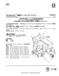
ThermoLazer® 200/200TC/300TC and
ThermoLazer ProMelt™ Pavement Marking
Systems
3A1320F
EN
- For professional application of thermoplastic traffic marking compound materials
(reflective beads applied simultaneously with screeding) - For outdoor use only (not to be operated in rain or damp conditions) Fuel: LP Gas (Propane Vapor)
Burner capacities: See Technical Data, page 44
Material capacity (max): 200-300 lb (91-136 kg)
ThermoLazer 200/200TC
IMPORTANT SAFETY INSTRUCTIONS
Read all warnings and instructions in this
manual. Save these instructions.
Related Manuals:
Operation
3A1319
Parts
3A1321
Double Bead
3A0004
3A1738
SmartDie™ II
3A1738
FlexDie™
ti22634a
ThermoLazer ProMelt
ti23073a
ThermoLazer 300TC
ti23074a
System Chart
System Chart
SmartDie II used on ThermoLazer 300TC/ProMelt only.
Smart Die II
Part No.
Smart Die Description
17A173
2 in. (5 cm)
24H431
3 in. (8 cm)
24H426
4 in. (10 cm)
24H432
5 in. (12 cm)
24H427
6 in. (15 cm)
24H433
7 in. (18 cm)
24H428
8 in. (20 cm)
24H434
9 in. (22.5 cm)
24H429
10 in. (25 cm)
24H430
12 in. (30 cm)
17A174
16 in. (40 cm)
24H437
3-3-3 in. (8-8-8 cm)
24H435
4-3-4 in. (10-8-10 cm)
24H436
4-4-4 in. (10-10-10 cm)
24J785
4-6-4 in. (10-15-10 cm)
17A175
6-4-6 in. (15-10-15 cm)
Requires 16” (40 cm) Conversion Bead System Kit for 300TC/ProMelt Only.
‡ 17B190 Kit, accy, 16” (40 cm) Single Drop Bead System
‡ 17B189 Kit, accy, 16” (40 cm) Double Drop Bead Box (requires 17B190 to be installed)
FlexDie used on ThermoLazer 200/200TC only.
2
FlexDie
Part No.
FlexDie Description
16Y661
16Y662
16Y320
16Y663
16Y190
16Y664
16Y326
16Y665
16Y332
16Y207
16Y338
16Y352
16Y666
16Y363
2 in. (5 cm)
3 in. (8 cm)
4 in. (10 cm)
5 in. (12 cm)
6 in. (15 cm)
7 in. (18 cm)
8 in. (20 cm)
9 in. (22.5 cm)
10 in. (25 cm)
12 in. (30 cm)
3-3-3 in. (8-8-8 cm)
4-3-4 in. (10-8-10 cm)
4-2-4 in. (10-5-10 cm)
4-4-4 in. (10-10-10 cm)
3A1320F
System Chart
Contents
System Chart . . . . . . . . . . . . . . . . . . . . . . . . . . . . . . 2
Warnings . . . . . . . . . . . . . . . . . . . . . . . . . . . . . . . . . 4
Kettle Gas Safety Valve,
Kettle Temperature Control, and
Kettle Thermopile Diagnosis . . . . . . . . . . . . . . 6
Kettle Temperature Control . . . . . . . . . . . . . . . . . . 7
Replacement . . . . . . . . . . . . . . . . . . . . . . . . . . . . 7
Calibration . . . . . . . . . . . . . . . . . . . . . . . . . . . . . . 9
Kettle Thermometer . . . . . . . . . . . . . . . . . . . . . . . . 10
Replacement . . . . . . . . . . . . . . . . . . . . . . . . . . . 10
Calibration . . . . . . . . . . . . . . . . . . . . . . . . . . . . . 10
Adjust Kettle Pilot Ignitor Electrode Gap . . . . . . 11
Kettle Over-Temperature Switch Replacement
(ProMelt only) . . . . . . . . . . . . . . . . . . . . . . . . . 11
Thermopile Replacement . . . . . . . . . . . . . . . . . . . 12
Removal and Installation of Electrode . . . . . . . . . 14
Pilot Burner . . . . . . . . . . . . . . . . . . . . . . . . . . . . . . 16
(ThermoLazer 200TC/300TC/ProMelt) . . . . . . . 16
Cleaning Kettle Main Burner Gas Lines . . . . . . . 18
Cleaning Kettle Pilot Burner Gas Lines . . . . . . . . 18
Securing Bead Dispenser Wheel . . . . . . . . . . . . . 19
Bead Dispense Tension Adjustment . . . . . . . . . 19
Linkage Rod Adjustment . . . . . . . . . . . . . . . . . . 19
Screed Box/Bead Dispenser Box Actuator . . . . . 20
Screed Box Pivot Arm Loading . . . . . . . . . . . . . . 20
(ThermoLazer 300TC/ProMelt only) . . . . . . . . . 20
Carbide Runner Replacement on Screed Box . . 21
(1 on each side) . . . . . . . . . . . . . . . . . . . . . . . . . 21
3A1320F
Kettle Gas Regulator Replacement . . . . . . . . . . . 22
ThermoLazer 200/200TC . . . . . . . . . . . . . . . . . . 22
ThermoLazer 300TC . . . . . . . . . . . . . . . . . . . . . 23
ThermoLazer ProMelt . . . . . . . . . . . . . . . . . . . . 24
Torch and Screed Burners Gas Regulator
Replacement (ThermoLazer 300TC/ProMelt) 25
Rear Screed Burner Assembly . . . . . . . . . . . . . . . 26
Front Screed Burner Assembly . . . . . . . . . . . . . . 27
(ThermoLazer 300TC/ProMelt) . . . . . . . . . . . . . 27
Screed Burner . . . . . . . . . . . . . . . . . . . . . . . . . . . . 29
(ThermoLazer 300TC/ProMelt) . . . . . . . . . . . . . 29
Screed Burner . . . . . . . . . . . . . . . . . . . . . . . . . . . . 30
Main Gas Filter
(ThermoLazer 300TC/ProMelt) . . . . . . . . . . . . 31
Screed Burner Filter . . . . . . . . . . . . . . . . . . . . . . . . 31
Troubleshooting . . . . . . . . . . . . . . . . . . . . . . . . . . . 32
Piping Diagram . . . . . . . . . . . . . . . . . . . . . . . . . . . . 38
ThermoLazer 200 . . . . . . . . . . . . . . . . . . . . . . . 38
ThermoLazer 200TC . . . . . . . . . . . . . . . . . . . . . 39
Wiring Diagram . . . . . . . . . . . . . . . . . . . . . . . . . . . . 41
ThermoLazer 200TC . . . . . . . . . . . . . . . . . . . . . 41
ThermoLazer 300TC . . . . . . . . . . . . . . . . . . . . . 42
ThermoLazer ProMelt . . . . . . . . . . . . . . . . . . . . 43
Technical Data . . . . . . . . . . . . . . . . . . . . . . . . . . . . 44
Notes . . . . . . . . . . . . . . . . . . . . . . . . . . . . . . . . . . . . 45
Graco Standard Warranty . . . . . . . . . . . . . . . . . . . 46
3
Warnings
Warnings
The following warnings are for the setup, use, grounding, maintenance, and repair of this equipment. The exclamation point symbol alerts you to a general warning and the hazard symbols refer to procedure-specific risks. When
these symbols appear in the body of this manual or on warning labels, refer back to these Warnings. Product-specific
hazard symbols and warnings not covered in this section may appear throughout the body of this manual where
applicable.
WARNING
FIRE AND EXPLOSION HAZARD
Flammable fumes and liquids, such as propane gas, gasoline and combustible fuel, in work area can
ignite or explode. To help prevent fire and explosion:
• Do not use equipment unless fully trained and qualified.
• Do not allow open containers of flammables within 25 ft (7.6 m) of equipment. Do not operate equipment within 10 ft (3 m) of any structure, combustible material, or other gas cylinders.
• Shut off all burners when adding fuel to equipment.
• Close the tank shut-off valve immediately if you smell propane gas; extinguish all open flames. If gas
odor continues, keep away from equipment and immediately call the fire department.
• Follow lighting instructions for the burner and torch.
• Do not heat thermoplastic traffic marking compound material above its maximum temperature rating.
• Fire extinguisher equipment shall be present and working.
• Keep work area free of debris, including solvent, rags and gasoline.
EQUIPMENT MISUSE HAZARD
Misuse can cause death or serious injury.
• Do not leave equipment unattended.
• Keep children and animals away from work area.
• Do not exceed the maximum working pressure or temperature rating of the lowest rated system
component. See Technical Data in all equipment manuals.
• Check equipment daily. Repair or replace worn or damaged parts immediately with genuine
manufacturer’s replacement parts only.
• Do not alter or modify equipment.
• Use equipment only for its intended purpose. Call your Graco distributor for information.
• Do not fill material beyond maximum capacity.
• Route gas lines, hoses, wires and cables away from traffic areas, sharp edges, moving parts, and hot
surfaces.
• Do not kink or overbend gas lines.
• Do not override or defeat safety devices.
• Do not operate the unit when fatigued or under the influence of drugs or alcohol.
BURN HAZARD
Equipment surfaces and fluid that is heated can become very hot during operation. To avoid severe
burns:
• Do not touch hot fluid or equipment.
CARBON MONOXIDE HAZARD
Exhaust contains poisonous carbon monoxide, which is colorless and odorless. Breathing carbon
monoxide can cause death. Do not operate in an enclosed area.
TOXIC FLUID OR FUMES HAZARD
Toxic fluids or fumes can cause serious injury or death if splashed in the eyes or on skin, inhaled, or swallowed.
• Read MSDS to know the specific hazards of the materials you are using.
4
3A1320F
Warnings
WARNING
PERSONAL PROTECTIVE EQUIPMENT
Wear appropriate protective equipment when in the work area to help prevent serious injury, including eye
injury, hearing loss, inhalation of toxic fumes, and burns. This protective equipment includes but is not
limited to:
• Clothing and respirator as recommended by the fluid, material, and solvent manufacturer.
• Gloves, shoes, overalls, face shield, hat, etc. rated for elevated temperatures of at least 500° F
(260° C).
CALIFORNIA PROPOSITION 65
Exhaust from this product contains a chemical known to the State of California to cause
cancer, birth defects or other reproductive harm.
This product contains a chemical known to the State of California to cause cancer, birth defects or other
reproductive harm. Wash hands after handling.
3A1320F
5
Kettle Gas Safety Valve, Kettle Temperature Control, and Kettle Thermopile Diagnosis
Kettle Gas Safety Valve,
Kettle Temperature Control, and
Kettle Thermopile Diagnosis
Terminal Connections
3
Connect millivolt meter to appropriate terminals (see
Terminal Connections).
Step
1
Gas safety
valve
2 and 3
Closed
2
Temperature
control
1 and 2
Closed
TP
TH
TH
TP
The gas safety valve, temperature control and thermopile can be checked by using a millivolt meter. Before
checking, make certain all electrical connections are
clean and tight.
Status of
Temperature
Part(s) to Be
Terminal
Control
Checked
Connections
Contacts
2
1
ti14524c
Desired
Meter
Reading
Diagnosis
Greater than If mV reading > 100 mV and the automatic valve (main
100 mV
burners) does not come on, replace the gas safety valve.
If mV reading < 100mV, proceed with diagnostic steps 2
and 3.
Less than
80 mV
If reading > 80 mV:
•
Clean and tighten electrical connections at temperature control and gas safety valve.
•
Check valve to make sure wires are in good condition. Replace as required.
•
Rapidly change temperature setting on temperature
control to see if cycling cleans the contacts.
If the preceding fails to give mV reading < 80 mV, replace
temperature control.
3
Gas safety
valve magnet
and
thermopile
1 and 2
Open
Greater than If mV reading < 325 mV:
325 mV
•
Clean and tighten all electrical connections.
•
Adjust pilot burner to increase millivolt output (see
page 18).
If the preceding fails to give mV reading > 325 mV,
replace thermopile.
Check valve magnet after obtaining correct mV output for
thermopile:
•
Ignite pilot burner only and allow the mV reading to
stabilize.
•
Shut pilot burner (turn gas safety valve knob OFF).
Note the mV reading where magnet drops out.
If magnet unlocks at mV reading < 120 mV, the magnet is
OK. NOTE: When magnet unlocks a click can be heard
and mV reading may fluctuate slightly.
6
3A1320F
Kettle Temperature Control
Kettle Temperature Control
Replacement
8. Use screwdriver to remove four screws (221) and
remove temperature control enclosure (205) from
handle bar mounting plate (122).
When replacing temperature control, keep in mind that
the temperature probe is an integral part of the assembly. Do not make any sharp bends in the capillary tubing. Bends should be 0.25 in. (0.64 cm) in radius or
greater.
Be sure to seal capillary tubing with high temperature
mortar at kettle outlet.
9. Use screwdriver to disconnect wires (242 and 243
for ThermoLazer), (243 and 360 for ThermoLazer
ProMelt).
10. Use wrench and extension to remove nut (124) from
temperature probe (162).
11. Use needle-nosed pliers to remove clip (41) from
probe (162).
12. Pull probe (162) through nut and clamp openings.
13. Use flat screwdriver or a small chisel to chip away
mortar on inside and outside of kettle until probe
freely passes through.
14. Pull probe (162) completely out of kettle (14) and
remove from temperature control enclosure (205).
ThermoLazer 200TC
ti14557a
Removal
1. Empty kettle and clean all material out. Make sure
stud (318), nut (124), clip (41) and probe (162) are
completely free of material.
ti22652a
2. Use screwdriver to loosen hose clamps (160) and
disconnect hoses (189) from bead hopper (43).
ThermoLazer 300TC (24H622, 24H625)
3. Use wrench to remove four bolts (139) and remove
bead hopper (43).
ti17067a
41
4. Pull temperature capillary tube (162) and grommet
(350) free of heat shield (270).
5. Remove temperature control knob (AA) by hand.
AA
BB
124, 318
ThermoLazer ProMelt
(24H624)
ti14124a
ti17066a
6. Remove temperature control plastic 4-way insert
from shaft. Insert behind knob (AA).
7. Use screwdriver to remove two screws on temperature control slip-fit overlay ring (BB). Overlay ring
(BB) is attached to temperature control enclosure
(205).
41
124
15. .
3A1320F
7
Kettle Temperature Control
Installation (ThermoLazer 200TC)
(162) to screen (150) with three clips (41). Use needle-nose pliers to secure probe inside clips (41).
*Torque stud (318) to 7-15 in-lb./079-1.69 N•m.
1. Route tube through clips (1).
2. Route wire inside bracket (2) on inner wall of kettle.
2
NOTE: Make sure probe cannot come into contact
with material agitator once installed.
1
ti23234a
3. Install temperature control (162) to temperature
control enclosure (205) with two screws supplied
with temperature control. Install overlay ring (BB)
parallel with temperature probe.
AA
BB
ProMelt: Route probe (162) through Z-clips (2)
welded to kettle (14). Route probe through stud
welded to kettle. Tighten* nut (124) to stud securing
probe. Secure probe to angle clip welded to kettle
with clip (41). Use needle-nose pliers to secure
probe inside clip(41).
*Torque nut (124) to 7-15 in-lb./079-1.69 N•m.
ti14124a
4. Route wires and probe capillary tubing so they will
not be pinched when installing temperature control
enclosure (205) to ThermoLazer handle bar mounting plate (122).
4. Apply high temperature mortar to inside and outside
of kettle opening contact points after the probe is
installed and locked into position by the nut and
clamps.
5. ThermoLazer: Route wires (242, 243) through handle bar mounting plate (122). Use screwdriver to
connect and tighten wires (242, 243) to temperature
control (162).
ProMelt: Route wires (243, 360) through handle bar
mounting plate (122). Use screwdriver to connect
and tighten wires (243, 360) to temperature control
(122).
6. Install temperature control (162) to temperature
control enclosure (205) with two screws supplied
with temperature control. Install overlay ring (BB)
parallel with temperature probe.
NOTE: For best results, keep probe capillary tubing
in spiral coil.
5. Install in bracket, then attach bracket to kettle.
6. Install plastic 4-way insert on temperature control
shaft.
7. Install temperature control knob (AA) on temperature control shaft.
Installation (ThermoLazer 300TC/ProMelt)
1. Route new probe (162) through grommet (350).
2. Route probe:
a. Between tube, lock (71) and bracket, handle,
mount, and tube (19).
b. Through slotted hole in heat shield (270). Insert
grommet (350) in heat shield hole.
c.
Through kettle (14) probe opening.
3. ThermoLazer: Route probe through stud (318).
Insert stud through screen (150) and tighten* stud
(318) to screen (150) with nut (124). Secure probe
8
AA
BB
ti14124a
7. Route wires and probe capillary tubing so they will
not be pinched when installing temperature control
enclosure (205) to ThermoLazer handle bar mounting plate (122).
NOTE: For best results, keep probe capillary tubing
in spiral coil.
8. Install temperature control enclosure (205) to ThermoLazer handle bar mounting plate (122) with four
screws (221).
9. Install plastic 4-way insert on temperature control
shaft.
10. Install temperature control knob (AA) on temperature control shaft.
11. Install bead hopper (43) and use wrench to install
and tighten four bolts (139).
12. Connect hoses (189) to bead hopper (43) and use
screw driver to tighten hose clamps (160)
3A1320F
Kettle Temperature Control
Calibration
6. If the temperature control setting is lower than the
remote calibrated temperature setting on temperature probe, turn adjusting screw clockwise. Every
1/4 in. turn will change temperature 35° F (19.4° C).
To Check Kettle Temperature Control Calibration:
1. Move unit to an area with no wind.
2. Turn temperature control to 400° F (204° C).
3. Agitate material for 4 to 5 minutes.
4. After control has reached steady state temperature
and burners do not cycle more than once per minute, insert remote calibrated temperature probe in
material and directly adjacent kettle temperature
control probe.
5. Compare temperature of remote calibrated temperature probe to temperature setting on temperature control.
3A1320F
ti14523a
7. If the temperature control setting is higher than the
remote calibrated temperature probe, turn adjusting
screw counterclockwise--every 1/4 in. turn will
change temperature 35° F (19.4° C).
8. Recheck calibration by turning temperature control
to 410° F (210° C) and repeat steps 3-7.
9
Kettle Thermometer
Kettle Thermometer
Replacement
NOTE: The thermometer can only be replaced while the
material inside the kettle is warm. If material inside the
kettle is cold, it will adhere to the probe and cause it to
separate from the thermometer once it is unscrewed.
Calibration
To Check Kettle Thermometer Calibration:
1. Move ThermoLazer to an area with no wind.
2. Turn temperature control to 400° F (204° C).
1. Empty material from kettle until material level is just
below the thermometer probe (162) (approximately
1 inch of material).
2. Unscrew thermometer (38) from kettle coupling.
NOTE: Look inside the kettle to make sure the
probe is rotating at the same rate as the thermometer as you unscrew it. If the probe is sticking, use the
hand torch to heat the probe and material so that
the probe can rotate freely.
Installation
1. Apply pipe sealant to thermometer (38) threads.
2. Install new thermometer into kettle coupling and
tighten. NOTE: Make sure the face of the thermometer is position toward the front of the unit for optimal viewing (an approximately 15 degree angle).
3. Agitate material for 4 to 5 minutes.
4. After control has reached steady state temperature
and burners do not cycle more than once per minute, insert remote calibrated temperature probe in
material and directly adjacent kettle temperature
control probe.
5. Compare temperature of remote calibrated temperature probe to thermometer.
6. If kettle thermometer is lower than the remote calibrated temperature probe, turn adjusting screw
counterclockwise.
Adjusting Screw
RESET
ti14525b
7. If the kettle thermometer is higher than the remote
calibrated temperature probe, turn adjusting screw
clockwise.
10
3A1320F
Adjust Kettle Pilot Ignitor Electrode Gap
Kettle Over-Temperature
Switch Replacement
Adjust Kettle Pilot Ignitor
Electrode Gap
(ProMelt only)
(ThermoLazer 300TC/ProMelt only)
1. Loosen screw (231).
2. Rotate ignitor electrode (7) until gap of 0.17 to 0.20
in. (0.43 to 0.51 cm) is achieved.
3. Retighten screw (231).
Removal
1. Unscrew switch fitting from kettle. NOTE: To keep
wire sleeve from twisting, counter-rotate sleeve
when turning switch fitting.
0.17 - 0.20 in.
2. Disconnect wire leads from switch terminals.
7
ti14519b
ti17078b
3. Unscrew switch and remove.
Installation
1. Apply anti-seize (LPS-04110 or equal) to switch
(339).
2. Install switch and torque to 120 - 140 in-lb (13.6 15.8 N•m).
3. Apply anti-seize (LPS-04110 or equal) to switch
fittings (343).
4. Connect wire leads (359 and 360) to switch.
5. Install switch fitting and torque to 180 - 200 in-lb
(20.3 - 22.6 N•m). NOTE: To keep wire sleeve from
twisting, counter-rotate sleeve when turning switch
fitting.
3A1320F
11
Thermopile Replacement
Thermopile Replacement
Removal
1. Shut off gas valve on LP-tank and disconnect hose.
28
ti14854a
ti14128a
2. Remove gas safety valve enclosure back cover
(29).
7. Disconnect gas pilot line (49) at gas pilot coupling
(171).
ThermoLazer 300TC/ProMelt Shown
171
49
ti14856b
29
ti14880a
3. Remove cover (320) from gas safety valve enclosure (28).
ThermoLazer 200TC/300TC/ProMelt
8. Thermolazer 300TC/ProMelt only: Disconnect
electrode lead (217) from pulse fire igniter (126).
Pull electrode out of wire sleeving.
28
217
320
126
ti21952a
ti14852a
4. Disconnect thermopile wires from gas safety valve
(13).
9. Remove gas pilot mounting housing (319) from gas
burner mounting plate (18). Disconnect ground lead
wire (244).
13
ThermoLazer 300TC/ProMelt
Shown
18
ti14853a
5. Remove wire strain relief fitting (357) from gas
safety valve enclosure (28).
319
ti14857b
244
10. Remove thermopile (7).
ThermoLazer 300TC/ProMelt
only
28
7
ti14855a
357
6. Pull thermopile wire out of gas safety valve enclosure (28).
ti14858b
ThermoLazer
200TC/300TC/ProMelt
11. Pull thermopile out of wire sleeving.
12
3A1320F
Thermopile Replacement
Installation
1. Replace thermopile (7).
13
7
ti14866a
8. Replace cover (320) on gas safety valve enclosure
(28).
ti14862b
2. Install gas pilot mounting plate (319) to gas burner
mounting plate (18). Connect ground lead wire
(244).
320
ThermoLazer 300TC/ProMelt
Shown
18
28
319
ti14867a
244
9. Replace gas safety enclosure back cover (29).
ti14863b
3. Connect gas pilot line (49) at gas pilot coupling
(171).
ThermoLazer 300TC/ProMelt
Shown
171
49
29
ThermoLazer 300TC/ProMelt
Shown
ti14861b
ti14881a
4. Pull thermopile through wire sleeving.
10. ThermoLazer 300TC/ProMelt Only: Pull electrode
wire through wire sleeving.
5. Guide thermopile wire into gas safety valve enclosure (28).
11. ThermoLazer 300TC/ProMelt Only: Connect electrode lead to pulse fire igniter.
28
ti14864a
6. Replace wire strain relief fitting (357) on gas safety
valve enclosure (28).
ti21951a
12. Reconnect hose and turn LP-gas tank valve ON.
ThermoLazer 300TC/ProMelt
Shown
28
ti14865a
357
7. Connect thermopile wires to gas safety valve (13).
See Wiring Diagram and Parts manual 3A1321 for
additional details.
3A1320F
ti14127a
13. Check for gas leaks at final assembly (see Operation manual).
13
Removal and Installation of Electrode
Removal and Installation of Electrode
(ThermoLazer 300TC/ProMelt only)
Removal
5. Remove electrode.
1. Disconnect gas pilot line (49) at gas pilot coupling
(171).
171
ti121953a
49
ti14861b
ThermoLazer 300TC/ProMelt Only
2. Disconnect electrode lead (217) from pulse fire
igniter (126). Pull electrode out of wire sleeving.
217
126
Installation
1. Replace electrode. (See Operation Manual for correct spacing between electrode and pilot burner).
ti21952a
ThermoLazer 300TC/ProMelt Only
3. Remove gas pilot mounting housing (319) from gas
burner mounting plate (18). Disconnect ground lead
wire (244).
ti14857b
18
319
ti21954a
244
2. Replace thermopile (7).
4. Remove thermopile (7).
7
7
ti14858b
14
ti14862b
3A1320F
Removal and Installation of Electrode
3. Install gas pilot mounting plate (319) to gas burner
mounting plate (18). Connect ground lead wire
(244).
6. Connect electrode lead to pulse fire igniter.
ThermoLazer 300TC/ProMelt
Shown
18
319
244
ti21951a
ThermoLazer 300TC/ProMelt Only
ti14863b
4. Connect gas pilot line (49) at gas pilot coupling
(171).
7. Reconnect hose and turn LP-gas tank valve ON.
171
49
ti14861b
ti14127a
5. Pull electrode wire through wire sleeving.
3A1320F
8. Check for gas leaks at final assembly (see Operation manual).
15
Pilot Burner
Pilot Burner
(ThermoLazer 200TC/300TC/ProMelt)
Removal
1. Disconnect gas pilot line (49) at gas pilot coupling
(171).
5. ThermoLazer 300TC/ProMelt only: Remove electrode.
ti121953a
171
49
ti14861b
ThermoLazer 300TC/ProMelt Only
2. ThermoLazer 300TC/ProMelt only: Disconnect
electrode lead (217) from pulse fire igniter (126).
Pull electrode out of wire sleeving.
ti21952a
6. Remove pilot burner.
217
126
ti22062a
ThermoLazer 300TC/ProMelt Only
3. Remove gas pilot mounting housing (319) from gas
burner mounting plate (18).
ThermoLazer 300TC/ProMelt only: Disconnect
ground lead wire (244).
7. Remove pilot burner tubing.
ti14857b
18
319
244
4. Remove thermopile (7).
ti122061a
7
ti14858b
16
3A1320F
Pilot Burner
Installation
5. Install gas pilot mounting plate (319) to gas burner
mounting plate (18).
ThermoLazer 300TC/ProMelt only: Connect
ground lead wire (244).
1. Install pilot burner tubing.
18
319
244
ti14863b
6. Connect gas pilot line (49) at gas pilot coupling
(171).
171
ti122061a
49
2. Install pilot burner.
ti14856b
7. ThermoLazer 300TC/ProMelt only: Pull electrode
wire through wire sleeving.
8. ThermoLazer 300TC/ProMelt only: Connect electrode lead to pulse fire igniter.
ti21951a
ti22059a
3. ThermoLazer 300TC/ProMelt only: Install electrode.
ti21954a
ThermoLazer 300TC/ProMelt only
9. Reconnect hose and turn LP-gas tank valve ON
ThermoLazer 300TC/ProMelt only
4. Install thermopile.
ti14127a
10. Check for gas leaks at final assembly (see Operation manual).
ti4862b
3A1320F
17
Cleaning Kettle Main Burner Gas Lines
Cleaning Kettle Main
Burner Gas Lines
Cleaning Kettle Pilot
Burner Gas Lines
1. Disconnect gas tubing line (49) from gas tube fitting
tee (165).
1. Disconnect gas tubing line (186) from gas tubing
line (118).
2. Insert rubber hose over gas tubing tee (165) and
force air into tubing at 30 psi (2.1 bar).
2. Insert rubber hose over gas tubing (118) and force
air into gas tubing line (118) at 30 psi (2.1 bar).
3. Reconnect gas tubing line (49) to gas tube fitting tee
(165).
3. Reconnect gas tubing line (186) to gas tubing tee
(118).
49
165
ti14559b
186
ti24817a
118
ThermoLazer 300TC/ProMelt shown
18
3A1320F
Securing Bead Dispenser Wheel
Securing Bead Dispenser
Wheel
To properly dispense beads, drive wheel (27) must be in
direct contact with tire (89). If drive wheel (27) becomes
loose and/or starts to slip, use allen wrench to tighten set
screw (211).
NOTE: To ensure proper contact between drive wheel
(27) and tire (81), make sure air pressure is always at 60
psi (4.14 bar).
Linkage Rod Adjustment
(ThermoLazer 300TC/ProMelt only)
Adjustments can be made to linkage rods by removing
clevis cotter hairpin (268), clevis pin from clevis (179),
loosening nuts (128), and then turning clevis as required
to lengthen or shorten rod connectors.
To ensure proper application of beads and thermoplastic,
make sure screed box linkage rod (182) measures 13.13
in. (33.34 cm). Be sure to measure where nut (128)
meets clevis (179) when checking for proper linkage rod
length.
211
13.13 in.
(33.34 cm)
181
81
27
ti14564a
Bead Dispense Tension
Adjustment
182
(ThermoLazer 200TC only)
When screed box is down, turn bolt/knob clockwise to
increase spring force.
Make sure bead dispense wheel engaged unit wheel.
Put screed box in STO position. Make sure bead wheel
does not contact unit wheel. If it does, turn knob to
decrease spring force.
ti14565a
Adjust the bead box linkage rod (181) so bead box drive
wheel (27) is touching ThermoLazer tire (81) when
screed box is in down (but not open) position. A slight
downward force on the bead box rod (181) should be
required when inserting the clevis pin through the clevis
(179) and deployment bar (78).
1. With screed box in down (but not open) position,
rotate the bead box wheel by hand.
ti14882a
81
ti23692a
3A1320F
27
2. If the wheel does not cause the ThermoLazer tire to
rotate both forward and backwards, loosen nuts
(128), remove clevis cotter hair pin (268), remove
clevis pin from clevis (179), and rotate the clevis
(179) one turn counterclockwise.
19
Screed Box/Bead Dispenser Box Actuator
78
268
179
128
ti14883a
3. Reconnect clevis to deployment bar and again
rotate bead box wheel to see if adjustments cause
ThermoLazer to move forward and backwards.
4. Continue to rotate clevis 1/2 turn counterclockwise
until rotating bead box wheel causes ThermoLazer
to move forward and backwards.
5. Lock nut (128) to clevis when final adjustment has
been made.
NOTE: Linkage rod (182): If converting from SmartDie
to SmartDie II, use Die Link Kit 24J714.
ti14604a
Screed Box Pivot Arm
Loading
(ThermoLazer 300TC/ProMelt only)
Preload screed box pivot arm to ensure gate closes fully
before lifting screed box off the ground. If screed box
leaks when closing and lifting, increase loading.
1. Unhook bottom of box pivot arm spring (199).
Screed Box/Bead
Dispenser Box Actuator
(ThermoLazer 300TC/ProMelt only)
If the screed box/bead dispenser box actuator does not
remain in the “down and locked” position, adjust the
3/4-16 lock nut by turning clockwise 1/4 to 1/2 turn or
until the actuator does not freely rotate.
ti14628b
2. Move bottom of box pivot arm spring to desired hole
and reconnect. Moving the spring in will decrease
loading, while moving the spring out will increase
loading.
ti14629b
20
3A1320F
Carbide Runner Replacement on Screed Box
Carbide Runner Replacement on Screed Box
(1 on each side)
Installation
NOTICE
Carbide runners need to be replaced one side at a
time. If both runners are removed, adjustment will be
lost and screed box will need to be reassembled by a
Graco approved technician.
1. Apply grease to groove where carbide runner sits.
1. Remove screed box.
ti16845a
ti16839a
ThermoLazer 300TC/ProMelt shown
2. Use allen wrench to loosen and remove upper pivot
bolt (511) to free yoke (502).
2. Replace plate, die runner (504) with new plate, die
runner. See Parts manual 3A1321.
3. While applying pressure to shear bar (506) directly
over support bar (509), use allen wrench to replace
and tighten four screws (513). There should be no
gap between the shear bar and support bar when
applying pressure.
ti17068a
ti16843a
3. Turn unit upside-down and use an allen wrench to
remove four screws (513) and plate, die runner
(504).
4. Use allen wrench to replace and tighten pivot bolt
(511) on yoke (502).
ti16843a
ti16845a
5. Install screed box.
ti16846a
ThermoLazer 300TC/ProMelt shown
3A1320F
21
Kettle Gas Regulator Replacement
Kettle Gas Regulator Replacement
ThermoLazer 200/200TC
Removal
Installation
1. Close propane tank valve.
1. Apply pipe sealant and install regulator (10) so flow
arrows point at the manifold.
2. Install fittings (415).
3. Install manifold (e) in unit and tighten bolts (415).
4. Connect lines to front (b) and rear (d) screed
torches and main kettle burner (c).
ti14128a
2. Disconnect gas supply hose (a) from propane tank.
5. Connect gas supply hose to propane tank (a).
3. Disconnect lines to front (b) and rear (c) screed
torches and main kettle burner (d).
6. Open propane tank valve.
4. Remove bolts (415) holding manifold to unit.
5. Unscrew fittings (410) and regulator (10).
ti14127a
7. Check for leaks.
8. Verify gauge PSI. Gauge should read 3 PSI ± 1. If
higher than 4 PSI, slightly open torch valve and
recheck.
10
aIN
OUT
e
410
415
b
c
d
ti23236a
FIG. 1
22
3A1320F
Kettle Gas Regulator Replacement
ThermoLazer 300TC
Removal
2. Apply pipe sealant to pipe elbow (142) and screw
into new gas regulator (10). Turn connection until
gas tight.
1. Close manual gas shut-off valve on propane tank.
NOTE: Make sure IN connection of regulator is connected to the pipe elbow (142). See FIG. 2
3. Apply pipe sealant to fitting (408) and screw into
elbow (401).
ti14128a
2. Disconnect gas supply hose from propane tank.
4. Connect gas tube (118) to fitting (410). Turn connection until gas tight.
3. Disconnect gas tube (118) from fitting (410).
5. Connect gas supply hose to propane tank.
4. Unscrew pipe subassembly (408, 409, 410, 415)
from elbow (401).
5. Unscrew gas regulator (10) from pipe elbow (142).
6. Unscrew gas regulator (10) from fitting (64).
ti14411a
Installation
6. Open manual gas shut-off valve on propane tank.
1. Apply pipe sealant to fitting (64) and screw into new
gas regulator (10). Turn connection until gas tight.
NOTE: Make sure OUT connection of regulator is
connected to the fitting (64). See FIG. 2
ti14127a
7. Check gas lines for gas leaks (see Operation
manual).
142
142
10
IN
10
Arrow
Indicates
Direction
of Gas
Flow
64
9
408
415
OUT
410
118
64
401
409
ti22015a
ti22066a
FIG. 2
3A1320F
23
Kettle Gas Regulator Replacement
ThermoLazer ProMelt
Removal
3. Place label (412) onto fitting (64). Add pipe sealant
to adapter fitting (323) and screw into new gas regulator. Turn connection until gas tight.
1. Close manual gas shut-off valve on propane tank.
NOTE: Make sure IN connection of regulator is connected to the pipe elbow (142). See FIG. 3
4. Apply pipe sealant to gauge (402). Screw gauge
(402) into tee (409). Turn connection until gas tight.
ti14128a
2. Disconnect gas supply hose from propane tank.
5. Connect gas tube (118) to fitting (151). Turn connection until gas tight.
3. Unscrew gauge (402) from tee (409).
6. Connect gas supply hose to propane tank.
4. Disconnect gas tube (118) at fitting (410).
5. Unscrew pipe subassembly (408, 409, 410) from
elbow (401).
6. Unscrew fitting (323) from fitting (64) and from gas
regulator (10).
ti14411a
7. Unscrew gas regulator (10) from pipe elbow (64).
7. Open manual gas shut-off valve on propane tank.
Installation
1. Apply pipe sealant to fitting (64) and screw into
adapter fitting (323). Turn connection until gas tight.
NOTE: Make sure OUT connection of regulator is
connected to adapter fitting (323). See FIG. 3
ti14127a
2. Apply pipe sealant to pipe elbow (142) and screw
into new gas regulator (10). Turn connection until
gas tight.
8. Check gas lines for gas leaks (see Operation
manual).
142
IN
142
10
OUT
10
412
323
Arrow
Indicates
Direction
of Gas
Flow
402
406
64
410
64
118
ti24818a
401
408
412
409
ti24819a
ti24818a
ti24819a
FIG. 3
24
3A1320F
Torch and Screed Burners Gas Regulator Replacement (ThermoLazer 300TC/ProMelt)
Torch and Screed Burners Gas Regulator Replacement
(ThermoLazer 300TC/ProMelt)
Removal
3. Apply pipe sealant to upstream pipe elbow (142)
and screw gas regulator (152); which is now connected to fitting (323). Turn connection until gas
tight.
1. Close manual gas shut-off valve on propane tank.
NOTE: Make sure IN connection of regulator is connected to the upstream pipe elbow (142). See 7.
4. Connect gas line at downstream tube elbows (161).
Turn connection until gas tight.
ti14128a
5. Connect gas supply hose to propane tank.
2. Disconnect gas supply hose from propane tank.
3. Disconnect gas line at downstream tube elbows
(161).
4. Unscrew gas regulator pipe train from upstream
pipe elbow (142).
ti14411a
5. Unscrew gas regulator (152) from fitting (323).
6. Unscrew and remove gas regulator (152) from
upstream pipe elbow (142).
6. Open manual gas shut-off valve on propane tank.
Installation
1. Apply pipe sealant to downstream pipe tee (12).
Screw pipe tee (12) with elbow (161) to fitting (323).
Turn connection until gas tight.
ti14127a
2. Apply pipe sealant to fitting (323) and screw into gas
regulator (152). Turn connection until gas tight.
7. Check gas lines for gas leaks (see Operation manual).
NOTE: Make sure OUT connection of regulator is
connected to fitting (323). See 7.
IN
142
IN
152
323
OUT
OUT
Arrow
Indicates
Direction
of Gas
Flow
152
12
323
161
ti24820a
161
7.
ti24820a
3A1320F
12
ti24821a
25
Rear Screed Burner Assembly
Rear Screed Burner Assembly
(ThermoLazer 300TC/ProMelt)
Removal
Installation
1. Close manual gas shut-off valve on propane tank.
1. Install burner manifold in mounting bracket (104,
109). Secure with snap rings (75). See FIG. 4.
2. Install burner assembly with mounting bracket to
bead dispenser.
3. Connect burner hose (98) to valve fitting (151).
ti14128a
4. Connect gas supply hose (99) to propane tank.
2. Disconnect gas supply hose (99) from propane
tank.
99
3. Disconnect gas tube (373) at valve fitting (151). See
FIG. 4.
ti14411a
4. Remove burner gas train mounting bracket fasteners (104, 109). Unscrew six screws (115). See FIG.
4.
5. Remove burner assembly.
5. Open manual shut-off valve on propane tank.
6. Remove snap rings (75) from gas manifold. See
FIG. 4.
ti14127a
373
151
104
115
75
ti22658a
FIG. 4
26
3A1320F
Front Screed Burner Assembly
Front Screed Burner Assembly
(ThermoLazer 300TC/ProMelt)
Removal
6. Remove screed burners.
1. Close manual gas shut-off valve on the propane
tank.
ti14128a
ti22060a
2. Disconnect gas supply hose from propane tank.
7. Remove gas manifold snap ring (75).
99
ti14411b
3. Remove screed box from screed housing (see
Operation manual).
4. Disconnect gas tubing at 45° elbow (32).
75
ti17074b
8. Unscrew gas manifold (less burners) mounting
bracket fasteners (146) and remove burner assembly (less burners) from front screed housing (20).
Installation
ti17072a
32
5. Unscrew front screed housing fasteners (146) and
remove front housing (20).
1. Install gas manifold (less screed burners) in bracket
support manifold (52) and screw gas manifold
mounting bracket to front screed housing (20) with
fasteners (146).
20
52
146
20
146
75
ti17073a
ti17074b
2. Install screed burner.
ti22060a
3A1320F
27
Front Screed Burner Assembly
6. Connect gas supply hose (99) to propane tank.
3. Install gas manifold snap ring (75).
4. Install front screed housing (20) to screed housing.
Secure with fasteners (146).
146
99
ti14411b
20
ti17073a
7. Open manual gas shut-off valve on propane tank.
5. Connect gas tubing to 45° elbow (32).
ti14127a
32
ti17072a
28
3A1320F
Screed Burner
Screed Burner
(ThermoLazer 300TC/ProMelt)
Vertical front screed burner (1)
Removal
Installation
1. Remove screed burner flame indicator (67).
1. Apply high-temperature thread sealant to 3/8-16
threads of orifice (60) and screw into burner (2).
NOTE: The orifice end with the smallest hole should
be screwed into the screed burner.
67
2
ti21955a
60
ti21958a
2. Unscrew screed burner and orifice from gas manifold.
2. Apply pipe sealant to 1/8 in. NPT thread of orifice fitting (60) and screw on adapter fitting (363). Install
washer on orifice (60).
60
ti21956a
3. Unscrew adapter fitting (363) from orifice fitting (60).
Remove washer from orifice (119).
363
ti21957a
3. Apply pipe sealant to 1/8 in. NPT thread of adapter
fitting (363) and screw into gas manifold.
60
119
363
363
ti21957a
4. Unscrew orifice fitting (60) from screed burner (2).
ti21956a
4. Install screed burner flame indicator (67).
2
67
60
ti21958a
ti21955a
3A1320F
29
Screed Burner
Screed Burner
Horizontal screed burner(s)
Removal
Installation
1. Remove screed burner flame indicator (67).
1. Apply high-temperature thread sealant to 3/8-16
threads of orifice (60) and screw into burner (2).
NOTE: The orifice end with the smallest hole should
be screwed into the screed burner.
67
ti17075b
60
ti17077b
2. Unscrew screed burner and orifice from gas manifold.
2
2. Apply pipe sealant to 1/8 in. NPT thread of orifice fitting (60) and screw on adapter fitting (363).
ti17076b
60
ti21950a
363
3. Unscrew adapter fitting (363) from orifice fitting (60).
3. Apply pipe sealant to 1/8 in. NPT thread of adapter
fitting (363) and screw into gas manifold.
60
ti21950a
363
ti17076b
363
4. Unscrew orifice fitting (60) from screed burner (2).
4. Install screed burner flame indicator (67).
60
ti17077b
2
30
67
ti17075b
3A1320F
Main Gas Filter (ThermoLazer 300TC/ProMelt)
Main Gas Filter
Screed Burner Filter
(ThermoLazer 300TC/ProMelt)
Removal
Removal
1. See Screed Burner Removal, page 29.
1. Unscrew filter fitting (403) from tee (12).
Install
2. Unscrew fitting (407) from hose (99).
1. See Screed Burner Install, page 29.
Install
1. Apply pipe sealant to 1/4 in. NPT of hose (99) and
screw on filter fitting (407).
2. Apply pipe sealant to 1/4 in. NPT of filter fitting (403)
and screw into tee (12).
3. Check gas lines for leaks. (See Operation Manual).
403
99
12
407
ti21960a
3A1320F
31
Troubleshooting
Troubleshooting
Problem
Kettle pilot burner does
not ignite or does not
remain ignited
Cause
Solution
Low or empty LP-gas tank
Replace with full tank.
Gas supply hose not connected to tank
Connect gas supply hose.
LP-gas tank shut-off valve closed
Open LP-gas tank shut-off valve.
Manual gas shut-off valve closed
Open manual gas shut-off valve.
Gas lines leaking or disconnected
Check for gas leaks. Connect and tighten fittings.
Kettle gas safety valve knob not in correct position
Turn knob to “PILOT” position and fully push
in (see Operation manual).
Not providing adequate time for thermopile to
heat up
See Operation manual.
Kettle pilot igniter has weak battery
Replace part (see Parts manual).
Kettle pilot electrode gap incorrect
Adjust gap (see page 11).
Incorrect flame length and/or gas pressure
Adjust flame and pressure (see Repair manual).
Strong wind blowing flame out
Move ThermoLazer out of strong winds.
Make sure burner view ports are closed.
Burner and/or gas lines plugged
Unplug holes and lines. Isolate all gas regulators if clearing line with forced air (see
page 6).
Kettle gas safety valve not functioning correctly
Replace part if it fails diagnostic test (see
page 6).
Thermopile not functioning correctly
Replace part if it fails diagnostic test (see
page 12).
Kettle pilot electrode ground wire not correctly
connected
Clean connections and retighten. Replace
ground wire if damaged.
Kettle pilot electrode lead wire has a short
Replace part (see Parts manual).
Kettle pilot igniter not functioning correctly
Replace part (see Parts manual).
Kettle burner regulator not functioning correctly
Replace part (see Parts manual).
Kettle burners shut off
Material level is low
before material is melted
Add material to kettle. Once material level is
up to thermometer, this condition will be corrected.
ProMelt Only
Replace part (see Parts manual).
32
Over temperature safety switch not functioning
correctly
3A1320F
Troubleshooting
Problem
Cause
Kettle main burners do
Kettle gas safety valve knob not at correct posinot ignite or are not burn- tion
ing correctly
Kettle temperature control dial set at a lower
temperature than material temperature
Kettle main burners do
not shut off
Kettle main burner does
not turn on
Solution
Turn knob to ON position (see Operation
manual).
Turn kettle temperature control dial to temperature 25° F (13.9° C) higher than material
temperature.
Kettle gas safety valve not functioning correctly
See Repair manual and replace part if it fails
diagnostic testing.
Burner and/or gas lines plugged
Unplug holes and lines. Isolate all gas regulators if clearing line with forced air (see
page 18).
Kettle temperature control not functioning correctly
Replace part (see Parts manual).
Gas lines have been disconnected
Connect and tighten hose fittings. Check for
gas leaks.
Incorrect flame length and/or gas pressure
Adjust flame and pressure (see page 18).
Kettle gas safety valve knob not at correct position
Replace part (see Parts manual).
Kettle temperature control dial is not turned to a
setting lower than material temperature
Turn kettle temperature control dial to a setting 25° F (13.9° C) (minimum) lower than
material temperature.
Kettle temperature control not functioning correctly
Replace part (see Parts manual).
Kettle gas safety valve not functioning correctly
Replace part if it fails diagnostic testing (see
page 6).
Kettle temperature control dial is not turned to a
setting higher than material temperature
Turn kettle temperature control dial to a setting 25° F (13.9° C) (minimum) higher than
material temperature.
Kettle temperature control not functioning correctly
Replace part (see Parts manual).
Kettle gas safety valve not functioning correctly
Replace part if it fails diagnostic test (see
page 6).
Over temperature safety switch not functioning
correctly
Replace part (see Parts manual).
Thermometer not match- Material has not reached temperature control set Allow time for material to reach operating
ing material temperature point
temperature.
in kettle
Material not fully agitated
Agitate material.
3A1320F
Cool or windy ambient conditions
Move ThermoLazer out of cool windy conditions. Discharge material and check thermometer.
Thermometer calibrated incorrectly
Calibrate thermometer (see page 10).
Kettle temperature control calibrated incorrectly
See Repair manual and replace part if it can
not be calibrated (see Parts manual).
Thermometer not functioning correctly
Replace part (see Parts manual).
Kettle temperature control not functioning correctly
Replace part (see Parts manual).
Kettle gas safety valve not functioning correctly
Replace part if it fails diagnostic test (see
page 6).
Incorrect flame length and/or gas pressure
Adjust flame and pressure (see page 18).
33
Troubleshooting
Problem
Screed box burner does
not ignite, does not
remain ignited, or can
not change heat output
Torch does not ignite
Agitator crank handle is
hard to move
Cause
Solution
Empty LP-gas tank
Replace with full tank.
LP-gas tank shut-off valve closed
Open LP-gas tank shut-off valve.
Gas supply hose not connected to tank
Connect gas supply hose.
Gas lines leaking or disconnected
Check for gas leaks. Connect and tighten fittings.
Burner regulator/flow flame adjusting valve not
functioning correctly
Replace part (see Parts manual).
Burner orifice plugged
Clean or replace part (see Parts manual).
Burner assembly not functioning correctly.
Replace part (see Parts manual).
Empty LP-gas tank
Replace with full tank.
LP-gas tank shut-off valve closed
Open LP-gas tank shut-off valve.
Torch manual gas shut-off valve closed
Open manual shut-off valve.
Gas supply hose not connected to tank
Connect gas supply hose.
Gas lines leaking or disconnected
Check for gas leaks. Connect and tighten fittings.
Torch assembly not functioning correctly
Replace part (see Parts manual).
Material is cold
Allow time for material to reach operating
temperature.
Bushings are worn
Replace bushings (see Parts manual).
Linkage ball rod ends need lubrication
Add grease.
Foreign material lodged between agitator and
kettle
Remove material in kettle and CAREFULLY
dislodge and remove foreign material.
ControlFlow™ gate valve Cold material temperature
difficult to open
or close
Gate sticking in guides
Heat material to operating temperature.
Make sure thermometer is free to move.
Check for excess material in guides. Apply
heat as required and remove excess material. Add grease to lubricate guides.
Bushings are worn
Replace bushings (see Parts manual).
ControlFlow gate valve
leaking
Gate not completely closed
Close gate completely.
Foreign material lodged in gate opening
CAREFULLY dislodge and remove foreign
material.
Screed box leaking
Foreign material in screed box discharge opening
CAREFULLY dislodge and remove foreign
material.
Dirty screed box
CAREFULLY clean box. All moving parts
need to be free of debris.
Incorrect deployment rod linkage length
Adjust length (see page 19).
Incorrectly adjusted screed box/bead dispenser
box actuator
Adjust lever (see page 19).
Excessive material
buildup when starting
and stopping extruding
34
Worn screed box shear bar
Replace gate (see Parts manual).
Worn screed box shear bar stop
Replace trough (see Parts manual).
Screed box not adjusted to ground
See Operation manual.
Screed box open when ThermoLazer is
stationary
Synchronize ThermoLazer and screed box
motion.
Foreign material in screed box discharge opening
CAREFULLY dislodge and remove foreign
material.
Dirty screed box
CAREFULLY clean box. All moving parts
need to be free of debris.
3A1320F
Troubleshooting
Problem
Cause
Beads not discharging or Low bead level in bead hopper
discharging unevenly
Bead dispenser doors closed
3A1320F
Fill bead hopper.
Open doors as required to obtain desired
flow pattern width.
Bead dispenser drive wheel not engaged
Secure bead dispenser wheel (see page 19).
Bead dispenser drive wheel slipping
Tighten. Check air pressure (see page 19).
Debris in discharge opening of bead dispenser
Remove debris.
Debris on ThermoLazer tire or bead dispenser
wheel
Remove debris.
Moisture in beads
Remove wet beads. Dry hopper, bead hoses
and bead dispenser. Fill hopper with dry
beads.
Beads not discharging at Bead dispenser flow rate lever not correctly set
required flow rate
Bead dispenser drive wheel slipping
Hard pushing when
screed box is on ground
Solution
Rotate flow rate lever to correct position.
Tighten wheel and check tire pressure (see
page 19).
Bead dispenser doors not fully open
Open door fully.
Moisture in beads
Remove wet beads. Dry hopper, bead hoses
and bead dispenser. Fill hopper with dry
beads.
Moisture on road surface
Allow road surface moisture to dry.
Rough road surface
Smooth road surface.
Bead Dispenser low on material
Add material to bead hopper.
Screed box not adjusted correctly
See Operation manual.
35
Troubleshooting
Applying Material
Problem
Cause
Ragged line edges when extruding
Solution
Dirty screed box
CAREFULLY clean box. Discharge
opening and screed box plate runners need to be free of debris.
Cold material temperatures
Heat material as required.
Marking speed too fast
Slow ThermoLazer speed.
Rough material surface when extrud- Overheated material
ing
Moisture on road surface
Reduce heat.
Allow road surface moisture to dry.
Rough road surface
Smooth road surface.
Screed box low on material
Add material to screed box.
EXAMPLES:
Correct line application will produce a full straight line with sharp edges; correct color,
thickness and width; a firm bond to the surface; and have uniform reflectivity.
ti14507a
Insufficient adhesion (material bulges •
at beginning of line)
•
Material temperature too low
•
Raise material temperature.
ThermoLazer speed too fast
•
Decrease speed of
ThermoLazer.
•
Clear debris from road.
•
Wait for temperature of surface
to raise.
•
Debris on road
•
Surface temperature too cold
ti14508a
Rough and bumpy line
ti14509a
Gas bubbles in line
•
Debris on surface
•
Clear debris from surface.
•
Crust from overheated material
•
Lower material temperature.
•
Debris caught in screed box
•
Clean debris from screed box.
•
Material not covering road high
spot
•
Adjust screed box line thickness.
•
Moisture or solvent on surface
•
Remove solvent from surface.
•
Material is overheated
•
Lower temperature of material.
ti14510a
Ragged edges and gaps in line
• Material temperature is too low
• Raise material temperature.
• ThermoLazer speed is too fast
• Wait for change in ambient conditions to remove moisture.
• Reduce ThermoLazer speed.
ti14511a
36
3A1320F
Troubleshooting
Problem
Cause
Swollen rounded line
Solution
• Material temperature is too high
• Lower material temperature.
• Uneven road surface
• Apply to even road surfaces.
ti14512a
Material shadows on sides
• Screed box is not evenly riding on • Remove debris from screed box
substrate
lever rod.
• Inspect/replace damaged screed
box lever rod/lever arm.
ti14513a
Line is wavy
• Strong road surface camber
• Apply so camber does not influence application.
• Incorrect ThermoLazer operation
• Use correct application methods
(for example, try locking swivel
wheel).
• Cracks in road surface
• Repair cracks.
• Temperature stress from
overheating
• Lower temperature in material.
• Material applied too cold
• Increase material temperature.
• Material applied too thin
• Slow ThermoLazer speed to apply
thicker material.
• Material temperature is too low
• Raise material temperature.
ti14514a
Cracks in line
ti14515a
Rough edges and lines in surface
• Material is overheated or scorched • Lower material temperature.
• Moisture in road surface
• Wait until road surface is dry.
• Screed box does not fully close
• Clean screed box.
• Debris caught in screed box
• Clear debris from screed box.
• Worn screed box shear bar
• Replace screed box gate.
ti14516a
Jagged line ends; material drips
between lines
ti14517a
3A1320F
• Worn screed box trough shear bar • Replace screed box trough.
stop
• Allow surface temperature to
• Surface temperature too cold
increase.
37
Piping Diagram
Piping Diagram
ThermoLazer 200
ti23240
38
3A1320F
Piping Diagram
ThermoLazer 200TC
t123241
3A1320F
39
40
(24H624 ONLY)
(24H622, 24H625 ONLY)
Plug
(24H625 ONLY)
20 psi (1.38 bar) ThermoLazer 300TC and ThermoLazer ProMelt
0.5 psi (.034 bar); ThermoLazer 300TC
3 psi (0.21 bar) ThermoLazer ProMelt
ti24822a
Piping Diagram
ThermoLazer 300TC/ProMelt
3A1320F
Gas Safety Valve
3A1320F
Thermopile
White Wire
Thermopile
Red Wire
Wire Harness
ti24841a
Wire Harness
Thermostat
Thermopile
Wiring Diagram
Wiring Diagram
ThermoLazer 200TC
41
42
Pulse Igniter
Gas Safety Valve
Thermopile
White Wire
Wire Harness
Thermopile
Red Wire
Wire Harness
Thermostat
ti17214a
Igniter Electrode
Thermopile
Wiring Diagram
ThermoLazer 300TC
3A1320F
3A1320F
Pulse Igniter
Igniter Ground
Thermopile
White Wire
Gas Safety Valve
Thermopile
Red Wire
Wire Harness
Wire Harness
Hi Temp Sensor
ti17084a
Igniter Electrode
Thermopile
Wire Harness
Thermostat
Wiring Diagram
ThermoLazer ProMelt
43
Technical Data
Technical Data
ThermoLazer
200/200TC
(24U280)
(24U281)
Fuel
ThermoLazer 300TC
with Rear
Heat
(24H622)
Operating
Pressure
(psi - bar)
Maximum Heating
Capacity
Btu/hr (kW)
Material
Capacity
lb (kg)
250 (17.24)
Kettle burners
3
(0.21)
0.5
(0.034)
0.5
(0.034)
3
(0.21)
Torch
3
(0.21)
20
(1.38)
20
(1.38)
20
(1.38)
Screed box front burners
3
(0.21)
20
(1.38)
20
(1.38)
20
(1.38)
Screed box rear burners
3
(0.21)
20
(1.38)
N/A
20
(1.38)
(1) 30,000
(8.8)
(2) 30,000
(8.8)
(2) 30,000
(8.8)
(2) 100,000
(29.3)
Torch
10,000
(2.93)
100,000
(29.3)
100,000
(29.3)
100,000 (29.3)
Screed box front burner (sum of 3 burners)
27,000
(7.9)
27,000
(7.9)
27,000
(7.9)
27,000
(7.9)
Screed box rear burner (sum of 4 burners)
Kettle burners (sum of burners)
36,000 (10.6)
36,000 (10.6)
N/A
36,000 (10.6)
Total
103,000
(30.2)
193,000
(56.6)
157,000
(46.0)
263,000 (77.1)
Gas
20
(9.1)
Main kettle
200
(91)
Bead hopper
Maximum operating temperature - °F (°C)
Physical
(24H624)
Liquefied Petroleum Gas (LP-gas) (propane vapor)
Gas supply maximum pressure - psi (bar)
44
without Rear
Heat
(24H625)
ThermoLazer
ProMelt
20
(9.1)
20,30
(9.1, 13.6)
300 (136) - Thermoplastic traffic marking
compound materials
40 (18)
90 (40) - Type
II glass bead
450 (232)
450
(232)
450
(232)
Front tire pressure - psi (bar)
N/A
45
(3.10)
Rear tire pressure - psi (bar)
N/A
60
(4.14)
Weight - lb (kg)
260
(118)
Length - in. (m)
44 (1.12)
300
(136)
295
(134)
480
(249)
350
(159)
72 (1.83)
Height - in. (m)
39 (1.00)
51 (1.3)
Width - in. (m)
33 (0.84)
48 (1.22)
Igniter battery
N/A
AA (1.5 V)
3A1320F
Notes
Notes
3A1320F
45
Graco Standard Warranty
Graco warrants all equipment referenced in this document which is manufactured by Graco and bearing its name to be free from defects in
material and workmanship on the date of sale to the original purchaser for use. With the exception of any special, extended, or limited warranty
published by Graco, Graco will, for a period of twelve months from the date of sale, repair or replace any part of the equipment determined by
Graco to be defective. This warranty applies only when the equipment is installed, operated and maintained in accordance with Graco’s written
recommendations.
This warranty does not cover, and Graco shall not be liable for general wear and tear, or any malfunction, damage or wear caused by faulty
installation, misapplication, abrasion, corrosion, inadequate or improper maintenance, negligence, accident, tampering, or substitution of
non-Graco component parts. Nor shall Graco be liable for malfunction, damage or wear caused by the incompatibility of Graco equipment with
structures, accessories, equipment or materials not supplied by Graco, or the improper design, manufacture, installation, operation or
maintenance of structures, accessories, equipment or materials not supplied by Graco.
This warranty is conditioned upon the prepaid return of the equipment claimed to be defective to an authorized Graco distributor for verification of
the claimed defect. If the claimed defect is verified, Graco will repair or replace free of charge any defective parts. The equipment will be returned
to the original purchaser transportation prepaid. If inspection of the equipment does not disclose any defect in material or workmanship, repairs
will be made at a reasonable charge, which charges may include the costs of parts, labor, and transportation.
THIS WARRANTY IS EXCLUSIVE, AND IS IN LIEU OF ANY OTHER WARRANTIES, EXPRESS OR IMPLIED, INCLUDING BUT NOT
LIMITED TO WARRANTY OF MERCHANTABILITY OR WARRANTY OF FITNESS FOR A PARTICULAR PURPOSE.
Graco’s sole obligation and buyer’s sole remedy for any breach of warranty shall be as set forth above. The buyer agrees that no other remedy
(including, but not limited to, incidental or consequential damages for lost profits, lost sales, injury to person or property, or any other incidental or
consequential loss) shall be available. Any action for breach of warranty must be brought within two (2) years of the date of sale.
GRACO MAKES NO WARRANTY, AND DISCLAIMS ALL IMPLIED WARRANTIES OF MERCHANTABILITY AND FITNESS FOR A
PARTICULAR PURPOSE, IN CONNECTION WITH ACCESSORIES, EQUIPMENT, MATERIALS OR COMPONENTS SOLD BUT NOT
MANUFACTURED BY GRACO. These items sold, but not manufactured by Graco (such as electric motors, switches, hose, etc.), are subject to
the warranty, if any, of their manufacturer. Graco will provide purchaser with reasonable assistance in making any claim for breach of these
warranties.
In no event will Graco be liable for indirect, incidental, special or consequential damages resulting from Graco supplying equipment hereunder, or
the furnishing, performance, or use of any products or other goods sold hereto, whether due to a breach of contract, breach of warranty, the
negligence of Graco, or otherwise.
Graco Information
For the latest information about Graco products, visit www.graco.com.
For patent information, see www.graco.com/patents.
TO PLACE AN ORDER, contact your Graco distributor or call 1-800-690-2894 to identify the nearest distributor.
All written and visual data contained in this document reflects the latest product information available at the time of publication.
Graco reserves the right to make changes at any time without notice.
For patent information see, www.graco.com/patents.
Original instructions. This manual contains English. MM 3A1320
Graco Headquarters: Minneapolis
International Offices: Belgium, China, Japan, Korea
GRACO INC. AND SUBSIDIARIES • P.O. BOX 1441 • MINNEAPOLIS MN 55440-1441 • USA
Copyright 2011, Graco Inc. All Graco manufacturing locations are registered to ISO 9001.
www.graco.com
Revised F, October 2014