1
Instructions-Parts
XP Proportioners
3A0420T
EN
Mechanically linked fixed ratio plural-component system used for proportioning, mixing,
and spraying two component coatings. For professional use only.
Important Safety Instructions
Read all warnings and instructions in this
manual. Save these instructions.
See page 11 for maximum working pressure and model
information.
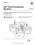
XP70 system shown with hoppers and optional
solvent flush pump and heaters.
r_571100_3A0420A_1a-2
Contents
Related Manuals . . . . . . . . . . . . . . . . . . . . . . . . . . . 3
Warnings . . . . . . . . . . . . . . . . . . . . . . . . . . . . . . . . . 4
Important Two-Component Material Information . 7
Isocyanate Conditions . . . . . . . . . . . . . . . . . . . . . 7
Material Self-ignition . . . . . . . . . . . . . . . . . . . . . . 7
Keep Components A and B Separate . . . . . . . . . 7
Moisture Sensitivity of Isocyanates . . . . . . . . . . . 7
Foam Resins with 245 fa Blowing Agents . . . . . . 7
Changing Materials . . . . . . . . . . . . . . . . . . . . . . . 8
A and B Component Designations . . . . . . . . . . . 8
Overview . . . . . . . . . . . . . . . . . . . . . . . . . . . . . . . . . . 9
Usage . . . . . . . . . . . . . . . . . . . . . . . . . . . . . . . . . 9
Over Pressure Protection . . . . . . . . . . . . . . . . . . 9
Initial System Setup . . . . . . . . . . . . . . . . . . . . . . . 10
Models . . . . . . . . . . . . . . . . . . . . . . . . . . . . . . . . . . 11
Cart-Mounted Systems . . . . . . . . . . . . . . . . . . . 11
Bare Proportioning Pump Packages . . . . . . . . . 13
Component Identification . . . . . . . . . . . . . . . . . . . 14
Fluid Control Assembly . . . . . . . . . . . . . . . . . . . 15
Main Air Controls . . . . . . . . . . . . . . . . . . . . . . . 15
45:1 Solvent Flush Pump Kit 262393 (optional) 16
Air Line . . . . . . . . . . . . . . . . . . . . . . . . . . . . . . . 17
Fluid Line Accessories . . . . . . . . . . . . . . . . . . . 17
Flush Before Using Equipment . . . . . . . . . . . . . 17
Setup . . . . . . . . . . . . . . . . . . . . . . . . . . . . . . . . . . . . 18
Location . . . . . . . . . . . . . . . . . . . . . . . . . . . . . . 18
Grounding . . . . . . . . . . . . . . . . . . . . . . . . . . . . . 18
Wire Systems with Explosion-Proof Heaters . . . 19
Motor Position . . . . . . . . . . . . . . . . . . . . . . . . . . 20
Connect Air Supply . . . . . . . . . . . . . . . . . . . . . . 21
Connect Static Mixers, Gun, and Hoses . . . . . . 21
Connect Fluid Hose Bundles (Remote Mix Manifold
Only) . . . . . . . . . . . . . . . . . . . . . . . . . . . . . . 21
Pressure Relief Procedure . . . . . . . . . . . . . . . . . . 22
Prime Empty System . . . . . . . . . . . . . . . . . . . . . . . 23
Prime A and B Fluids . . . . . . . . . . . . . . . . . . . . 23
Prime Solvent Flush Pump . . . . . . . . . . . . . . . . 24
Recirculate Prior to Spraying or Re-Prime After a
Pump Runs Dry . . . . . . . . . . . . . . . . . . . . . 25
Spray . . . . . . . . . . . . . . . . . . . . . . . . . . . . . . . . . . . . 26
B Side Mix Manifold Restriction . . . . . . . . . . . . . . 27
Flush Mixed Material . . . . . . . . . . . . . . . . . . . . . . . 28
Flush Mix Manifold, Hose, and Spray Gun . . . . 28
Empty and Flush Entire System
(new system or end of job) . . . . . . . . . . . . . . 29
2
Shutdown . . . . . . . . . . . . . . . . . . . . . . . . . . . . . . . . 30
Park . . . . . . . . . . . . . . . . . . . . . . . . . . . . . . . . . . . . . 30
System Verification . . . . . . . . . . . . . . . . . . . . . . . . 31
Maintenance . . . . . . . . . . . . . . . . . . . . . . . . . . . . . . 32
Hose Electrical Resistance . . . . . . . . . . . . . . . . 32
Filters . . . . . . . . . . . . . . . . . . . . . . . . . . . . . . . . . 32
Seals . . . . . . . . . . . . . . . . . . . . . . . . . . . . . . . . . 32
Cleaning Procedure . . . . . . . . . . . . . . . . . . . . . . 32
Recommended Spare Parts . . . . . . . . . . . . . . . 32
Change the Mix Ratio . . . . . . . . . . . . . . . . . . . . 32
Troubleshooting . . . . . . . . . . . . . . . . . . . . . . . . . . . 33
Pump Troubleshooting . . . . . . . . . . . . . . . . . . . 34
Repair . . . . . . . . . . . . . . . . . . . . . . . . . . . . . . . . . . . 35
Pump Assembly . . . . . . . . . . . . . . . . . . . . . . . . . 35
Air Controls . . . . . . . . . . . . . . . . . . . . . . . . . . . . 36
Mix Manifold Assembly . . . . . . . . . . . . . . . . . . . 38
Fluid Circulation Manifold with Over Pressure Relief
Valves . . . . . . . . . . . . . . . . . . . . . . . . . . . . . 38
Hoppers . . . . . . . . . . . . . . . . . . . . . . . . . . . . . . . 40
Optional Solvent Pump . . . . . . . . . . . . . . . . . . . 40
Optional Fluid Heaters . . . . . . . . . . . . . . . . . . . . 41
Parts . . . . . . . . . . . . . . . . . . . . . . . . . . . . . . . . . . . . 42
Cart-Mounted System . . . . . . . . . . . . . . . . . . . . 42
Bare Proportioning Pump Package . . . . . . . . . . 50
Air Controls, 258983 . . . . . . . . . . . . . . . . . . . . . 52
Fluid Circulation Manifold with Over Pressure Relief
Valve . . . . . . . . . . . . . . . . . . . . . . . . . . . . . . 53
Recommended Spare Parts . . . . . . . . . . . . . . . . . 54
Accessories and Kits . . . . . . . . . . . . . . . . . . . . . . . 55
Acceptable For Use in Explosive Atmospheres . 55
Not Approved For Explosive Atmospheres . . . . 56
Technical Data . . . . . . . . . . . . . . . . . . . . . . . . . . . . 57
Dimensions . . . . . . . . . . . . . . . . . . . . . . . . . . . . . . 58
Bare Proportioner Mounting Hole Dimensions . 60
Wall Mount Bracket 262812 Dimensions . . . . . . 61
Floor Stand 24M281 Dimensions . . . . . . . . . . . 62
Hydraulic Unit Dimensions . . . . . . . . . . . . . . . . 62
Graco Standard Warranty . . . . . . . . . . . . . . . . . . . 64
3A0420T
Related Manuals
Related Manuals
Manuals are available at www.graco.com. Component
manuals in English:
Manual
Description
312145
XTR™ 5 and XTR™ 7 Spray Guns
Instructions-Parts
Pump Package Components
307158
Viscount® II Hydraulic Motor Instructions-Parts
311238
NXT® Air Motor Instructions-Parts
311762
Xtreme® Displacement Pumps
Instructions-Parts
Hopper Kits
312747
406860
20 Gallon Double Wall Hopper Kit
Instructions-Parts
7 Gallon Hopper Installation Kit Instructions-Parts
Heating
309524
Viscon®
309525
Heated Hose Kit, Instructions-Parts
313259
Hopper or Hose Heat Circulation Kit
406861
Viscon HP Heater Adapter Kit, Instructions-Parts
HP Heater Instructions-Parts
Solvent Flush
310863
Feed and Solvent Flush Kits
312794
Merkur® Pump Assembly
Instructions-Parts
Accessories and Kits
309852
311486
312769
339361
Polyurethane Circulation and Return
Tube Kits, Instructions-Parts
DataTrak™ Conversion Kit, Instructions-Parts
Feed Pump and Agitator Kits
Instructions-Parts
High Pressure Hose and Accessories
Brochure
3A0421
Ratio Check Kit, Instructions-Parts
3A0590
Mix Manifold, Quickset Mix Manifold
Instructions-Parts
Gun Splitter Valve with Independent
Flush, Instructions-Parts
3A2573
406739
3A0420T
Desiccant Kit Instructions-Parts
3
Warnings
Warnings
The following warnings are for the setup, use, grounding, maintenance, and repair of this equipment. The exclamation point symbol alerts you to a general warning and the hazard symbols refer to procedure-specific risks. When
these symbols appear in the body of this manual, refer back to these Warnings. Product-specific hazard symbols and
warnings not covered in this section may appear throughout the body of this manual where applicable.
WARNING
WARNING
FIRE AND EXPLOSION HAZARD
Flammable fumes, such as solvent and paint fumes, in work area can ignite or explode. To help prevent
fire and explosion:
•
Use equipment only in well ventilated area.
•
Eliminate all ignition sources; such as pilot lights, cigarettes, portable electric lamps, and plastic drop
cloths (potential static arc).
•
Keep work area free of debris, including solvent, rags and gasoline.
•
Do not plug or unplug power cords, or turn power or light switches on or off when flammable fumes
are present.
•
Ground all equipment in the work area. See Grounding instructions.
•
Use only grounded hoses.
•
Hold gun firmly to side of grounded pail when triggering into pail.
•
If there is static sparking or you feel a shock, stop operation immediately. Do not use equipment
until you identify and correct the problem.
•
Keep a working fire extinguisher in the work area.
SPECIAL CONDITIONS FOR SAFE USE
• To prevent the risk of electrostatic sparking, the equipment’s non-metallic parts must be cleaned with
only a damp cloth.
•
Refer to the Viscon HP Heater manual for special conditions for safe use.
ELECTRIC SHOCK HAZARD
This equipment must be grounded. Improper grounding, setup, or usage of the system can cause electric
shock.
• Turn off and disconnect power at main switch before disconnecting any cables and before servicing
equipment.
• Connect only to grounded power source.
• All electrical wiring must be done by a qualified electrician and comply with all local codes and
regulations.
4
3A0420T
Warnings
WARNING
WARNING
SKIN INJECTION HAZARD
High-pressure fluid from gun, hose leaks, or ruptured components will pierce skin. This may look like just
a cut, but it is a serious injury that can result in amputation. Get immediate surgical treatment.
•
Do not spray without tip guard and trigger guard installed.
•
Engage trigger lock when not spraying.
•
Do not point gun at anyone or at any part of the body.
•
Do not put your hand over the spray tip.
•
Do not stop or deflect leaks with your hand, body, glove, or rag.
•
Follow the Pressure Relief Procedure when you stop spraying and before cleaning, checking, or
servicing equipment.
•
Tighten all fluid connections before operating the equipment.
•
Check hoses and couplings daily. Replace worn or damaged parts immediately.
EQUIPMENT MISUSE HAZARD
Misuse can cause death or serious injury.
•
Do not operate the unit when fatigued or under the influence of drugs or alcohol.
•
Do not exceed the maximum working pressure or temperature rating of the lowest rated system component. See Technical Data in all equipment manuals.
•
Use fluids and solvents that are compatible with equipment wetted parts. See Technical Data in all
equipment manuals. Read fluid and solvent manufacturer’s warnings. For complete information about
your material, request MSDS from distributor or retailer.
•
Do not leave the work area while equipment is energized or under pressure. Turn off all equipment
and follow the Pressure Relief Procedure when equipment is not in use.
•
Check equipment daily. Repair or replace worn or damaged parts immediately with genuine manufacturer’s replacement parts only.
•
Do not alter or modify equipment.
•
Use equipment only for its intended purpose. Call your distributor for information.
•
Route hoses and cables away from traffic areas, sharp edges, moving parts, and hot surfaces.
•
Do not kink or over bend hoses or use hoses to pull equipment.
•
Keep children and animals away from work area.
•
Comply with all applicable safety regulations.
MOVING PARTS HAZARD
Moving parts can pinch, cut or amputate fingers and other body parts.
3A0420T
•
Keep clear of moving parts.
•
Do not operate equipment with protective guards or covers removed.
•
Pressurized equipment can start without warning. Before checking, moving, or servicing equipment,
follow the Pressure Relief Procedure and disconnect all power sources.
5
Warnings
WARNING
WARNING
TOXIC FLUID OR FUMES HAZARD
Toxic fluids or fumes can cause serious injury or death if splashed in the eyes or on skin, inhaled, or swallowed.
•
Read MSDSs to know the specific hazards of the fluids you are using.
•
Store hazardous fluid in approved containers, and dispose of it according to applicable guidelines.
•
Always wear chemically impermeable gloves when spraying, dispensing, or cleaning equipment.
PERSONAL PROTECTIVE EQUIPMENT
You must wear appropriate protective equipment when operating, servicing, or when in the operating area
of the equipment to help protect you from serious injury, including eye injury, hearing loss, inhalation of
toxic fumes, and burns. This equipment includes but is not limited to:
•
Protective eyewear, and hearing protection.
•
Respirators, protective clothing, and gloves as recommended by the fluid and solvent manufacturer.
BURN HAZARD
Equipment surfaces and fluid that’s heated can become very hot during operation. To avoid severe burns:
•
6
Do not touch hot fluid or equipment.
3A0420T
Important Two-Component Material Information
Important Two-Component Material Information
Isocyanate Conditions
Spraying or dispensing materials containing
isocyanates creates potentially harmful mists,
vapors, and atomized particulates.
Read material manufacturer’s warnings and material
MSDS to know specific hazards and precautions
related to isocyanates.
Prevent inhalation of isocyanate mists, vapors, and
atomized particulates by providing sufficient
ventilation in the work area. If sufficient ventilation is
not available, a supplied-air respirator is required for
everyone in the work area.
To prevent contact with isocyanates, appropriate
personal protective equipment, including chemically
impermeable gloves, boots, aprons, and goggles, is
also required for everyone in the work area.
Material Self-ignition
Some materials may become self-igniting if applied
too thick. Read material manufacturer’s warnings and
material MSDS.
Keep Components A and B
Separate
Cross-contamination can result in cured material in
fluid lines which could cause serious injury or
damage equipment. To prevent cross-contamination
of the equipment’s wetted parts, never interchange
component A (isocyanate) and component B (resin)
parts.
3A0420T
Moisture Sensitivity of
Isocyanates
Isocyanates (ISO) are catalysts used in two component
foam and polyurea coatings. ISO will react with moisture
(such as humidity) to form small, hard, abrasive crystals,
which become suspended in the fluid. Eventually a film
will form on the surface and the ISO will begin to gel,
increasing in viscosity. If used, this partially cured ISO
will reduce performance and the life of all wetted parts.
NOTE: The amount of film formation and rate of crystallization varies depending on the blend of ISO, the
humidity, and the temperature.
To prevent exposing ISO to moisture:
•
Always use a sealed container with a desiccant
dryer in the vent, or a nitrogen atmosphere. Never
store ISO in an open container.
•
Keep the ISO pump wetcup or reservoir (if installed)
filled with Graco Throat Seal Liquid (TSL™), Part
206995. The lubricant creates a barrier between the
ISO and the atmosphere.
•
Use moisture-proof hoses specifically designed for
ISO.
•
Never use reclaimed solvents, which may contain
moisture. Always keep solvent containers closed
when not in use.
•
Never use solvent on one side if it has been contaminated from the other side.
•
Always lubricate threaded parts with TSL or grease
when reassembling.
Foam Resins with 245 fa
Blowing Agents
Some foam blowing agents will froth at temperatures
above 90°F (33°C) when not under pressure, especially
if agitated. To reduce frothing, minimize preheating in a
circulation system.
7
Important Two-Component Material Information
Changing Materials
•
Changing material types used in your system
requires special attention to avoid equipment damage and downtime.
•
Always clean the fluid inlet strainers after flushing.
•
When changing between epoxies and urethanes or
polyureas, disassemble and clean all fluid components and changes hose sets.
•
Check with your material manufacturer for chemical
compatibility.
•
Most materials use ISO on the A side, but some use
ISO on the B side.
•
Epoxies often have amines on the B (hardener)
side. Polyureas often have amines on the B (resin)
side.
A and B Component Designations
Material suppliers and markets refer to plural component materials differently. The table below summarizes the different designations for the components used in various machines.
Market
Equipment
Designations
Letter
Color
Foam and Polyurea, and All Reactors, HFR™,
Component Names
Urethane Pour
and VRM™
Major or Minor Component
(when not 1:1 mix)
Letter
Color
Epoxy and Urethane Hydra-Cat®, XtremeProtective Coatings Mix™, XM™, and XP Component Names
Major or Minor Component
(when not 1:1 mix)
Letter
Color
Epoxy, Silicone, Urethanes, and other mate- PR70™ and PR
Component Names
rials
Major or Minor Component
(when not 1:1 mix)
8
Machine Left Machine Right
Side
Side
A
B
Red
Blue
ISO, Hardener, Polyol, Resin,
Catalyst
Base
Low Volume
High Volume
Side
Side
A
B
Blue
Green
Hardener, CataResin, Base
lyst
High Volume
Low Volume
Side
Side
A
B
Red
Blue
Polyol, Resin, ISO, Hardener,
Base
Catalyst
High Volume
Low Volume
Side
Side
3A0420T
Overview
Overview
Usage
The XP is a mechanically linked fixed ratio system that
can mix and spray most two-component epoxy and urethane protective coatings. When using quick-setting
material (less than 10 minute pot life) a remote mix manifold must be used or materials must mix at the gun.
Quickset manifold 24M398 is recommended for
quick-setting material.
Over Pressure Protection
Mechanically linked pumps can create excessive fluid
pressure if the full motor force is applied to only one
of the fluid pumps.
•
Cart-Mounted Systems Only: Maximum air pressure set point blow off valves are provided to limit
maximum fluid pressure. Do not remove these
valves.
•
Color coded automatic over pressure relief
valves are used on cart-mounted systems to
dump excess fluid pressure back to the supply.
Never plug these return hoses. See Fluid Circulation Manifold with Over Pressure Relief
Valves on page 38.
•
When using an XP bare pump package to build a
system, use the over pressure relief valves referenced above.
•
Never install individual shut off valves on the “A”
and “B” lines. On cart-mounted systems, common handles link the fluid control valves.
•
On models other than 1:1 mix ratio, a rupture disc
is provided on the small side fluid pump (pumps
72cc and smaller) as a back-up to the over pressure relief valve. If the rupture disc ever opens,
do not operate the machine until the over pressure valve and the rupture disc have been
replaced.
•
If changing pump lowers or motor on your system, use the correct over pressure relief valves
from the chart on page 39.
The two pumps are carbide seat severe duty positive
displacement pumps that displace fluid on both strokes.
The XP systems are not approved for use in hazardous locations unless the base model, all accessories,
all kits, and all wiring meet local, state, and national
codes. See Important Two-Component Material
Information, page 7, to determine the appropriate
location for your particular XP model.
3A0420T
9
Initial System Setup
Initial System Setup
1. Check the shipment for accuracy. Ensure you have
received everything you ordered. See Component
Identification, page 14.
2. Check for loose fittings and fasteners.
3. Install optional solvent flush pump kit 262393, if
ordered. See manual 310863 for instructions.
4. Mount and connect optional heaters, if ordered. See
the heater adapter kit manual 406861 for instructions and the heater manual 309524.
5. Install desiccant kits if using polyurethane isocyanates in hoppers. See manual 406739 for instructions.
6. Install circulation and return tube kits if you are feeding material from drums or remote hoppers. See
manual 309852 if you are feeding urethane material.
7. Install hopper or hose heat circulation kit 24M224, if
ordered. See 313259 for instructions.
NOTE: Supply return lines must be used.
8. Connect the feed pumps, fluid strainers, and air
hoses as necessary. If your system does not use
hoppers, then see manual 312769.
9. Connect the air supply line. See Connect Air Supply, page 21.
10. Connect the fluid hose assembly, including the
static mixers, whip hose and gun. See Pressure
Relief Procedure, page 22.
11. Flush test oil from system as needed. See Empty
and Flush Entire System (new system or end of
job), page 29.
10
3A0420T
Models
Models
The XP systems are approved for use in hazardous
locations only if the base model, all accessories, all
kits, and all wiring meet local, state, and national
codes.
Cart-Mounted Systems
NOTE: All cart-mounted systems listed are Ex rated:
II 2 G c IIA T2
See Accessories and Kits on page 55 for a list of all optional accessories.
NOTE: The “Standard” mix manifold selection means the mix manifold is mounted on the cart and comes with mixers, 25 ft of 3/8 in. mix hose, and 10 ft of 1/4 in. whip hose. The “Quickset” mix manifold selection means the manifold
has dual flush valves, is mounted on a remote carriage, and comes with mixers and 10 ft of 1/4 in. whip hose. When
ordering the Quickset configuration, A and B hoses from the sprayer to the mix manifold must be ordered separately.
XP35 with NXT 3400 Air Motor
Typ
e
Pump
Model Package
281000
--281101
281102
281100
281105
281106
281201
281202
281200
281205
281206
262804
281252
262803
281255
281256
281301
281302
281300
281305
281306
281401
281402
281400
281405
281406
3A0420T
Volume
Mix
7 Gallon
Mix
Ratio Hoppers Manifold Hose
--35 ft
Standard
(10.7 m)
✔
1.0:1
----✔
35 ft
Standard
✔
(10.7
m)
2.0:1
2.5:1
3.0:1
4.0:1
Gun
Max Fluid
Max Air
Working Pressure
Pressure
Pressure
psi (MPa, bar)
psi (MPa, bar) Ratio
-------
XTR5
3500 (24, 241)
95 (0.65, 6.5)
38:1
3500 (24, 241)
85 (0.59, 5.9)
40:1
3500 (24, 241)
90 (0.62, 6.2)
34:1
3500 (24, 241)
100 (0.7, 7)
36:1
3500 (24, 241)
95 (0.65, 6.5)
38:1
--XTR5
✔
---
---
---
✔
Standard
35 ft
(10.7 m)
XTR5
✔
---
---
---
✔
Standard
35 ft
(10.7 m)
XTR5
✔
---
---
---
✔
Standard
35 ft
(10.7 m)
XTR5
✔
---
---
---
11
Models
XP70 with NXT 6500 Air Motor
XP50 with 6500 Air Motor
Typ
e
12
Pump
Model Package
282000
--282101
282102
282100
282105
282106
282151
282152
282150
282155
282156
282201
282202
282200
282205
282206
282251
282252
282250
282255
282256
282301
282302
282300
282305
282306
282331
282330
282332
282401
282402
282400
282405
282406
283101
282100
283102
283201
282200
283202
283301
282300
283302
283401
282400
283402
571000
--571101
571100
571102
571151
571150
571152
571201
571200
571202
571251
571250
571252
571301
571300
571302
571401
571400
571402
Volume
Mix
7 Gallon
Mix
Ratio Hoppers Manifold Hose
--35 ft
Standard
(10.7
m)
✔
1.0:1
----✔
35 ft
Standard
✔
(10.7
m)
1.5:1
2.0:1
2.5:1
3.0:1
3.3:1
4.0:1
Gun
XTR5
✔
---
✔
Standard
35 ft
(10.7 m)
XTR5
✔
---
---
---
✔
Standard
35 ft
(10.7 m)
XTR5
✔
---
---
---
✔
Standard
35 ft
(10.7 m)
XTR5
✔
---
---
---
Standard
35 ft
(10.7 m)
XTR5
---
---
---
✔
1.0:1
✔
2.0:1
✔
3.0:1
✔
4.0:1
✔
Quickset
100 (0.7, 7)
45:1
5000 (34, 344)
90 (0.62, 6.2)
55:1
4500 (31, 310)
100 (0.7, 7)
48:1
5000 (34, 344)
95 (0.65, 6.5)
52:1
4500 (31, 310)
100 (0.7, 7)
45:1
5000 (34, 344)
90 (0.62, 6.2)
56:1
4800 (33, 331)
100 (0.7, 7)
48:1
4500 (31, 310)
100 (0.7, 7)
45:1
4800 (33, 331)
100 (0.7, 7)
48:1
4500 (31, 310)
100 (0.7, 7)
45:1
4800 (33, 331)
100 (0.7, 7)
48:1
---
---
---
XTR5
---
✔
4500 (31, 310)
---
---
✔
Max Fluid
Max Air
Working Pressure
Pressure
Pressure
psi (MPa, bar)
psi (MPa, bar) Ratio
-------
10 ft
FlexPlus
(3.0 m)
--1.0:1
✔
7250 (50, 500)
95 (0.65, 6.5)
76:1
1.5:1
✔
7250 (50, 500)
80 (0.5, 5.5)
91:1
2.0:1
✔
7250 (50, 500)
95 (0.65, 6.5)
76:1
2.5:1
✔
6500 (45, 448)
100 (0.7, 7)
65:1
3.0:1
✔
6800 (47, 469)
100 (0.7, 7)
68:1
4.0:1
✔
7250 (50, 500)
100 (0.7, 7)
73:1
Standard
35 ft
(10.7 m)
XTR7
3A0420T
Models
Bare Proportioning Pump Packages
Packages include motor, pump lowers, and all connection hardware.
NOTE: All pump packages are Ex rated except for the
XP-h pump packages (284xxx):
II 2 G c IIA T2
Building systems with bare proportioning pump
packages:
• Over Pressure Protection must be used, see
page 9. See chart on page 39 to identify the over
pressure relief valves to use with your system.
•
All components must meet or exceed maximum
working pressures.
XP-h with
Viscount II
Hydraulic Motor
XP70 with
NXT 6500
Air Motor
XP50 with
NXT 6500
Air Motor
XP35 with
NXT 3400
Air Motor
Pump
Type Package
281100
281200
262803
281300
281400
282100
282150
282200
282250
282300
282330
282400
571100
571150
571200
571250
571300
571400
284101
284102
284103
284201
284202
284203
284251
284252
284253
284301
284302
284303
284401
284402
284403
3A0420T
A Side
Pump
L090C0
L115C0
L14AC0
L14AC0
L14AC0
L14AC0
L14AC0
L18AC0
L18AC0
L22AC0
L18AC0
L22AC0
L090C0
L085C0
L115C0
L14AC0
L14AC0
L14AC0
L22AC0
L14AC0
L090C0
L29AC0
L18AC0
L115C0
L29AC0
L18AC0
L14AC0
L29AC0
L22AC0
L14AC0
L29AC0
L22AC0
L14AC0
Hydraulically powered pump packages (XP-h) are not
available as complete systems. Refer to manual 307158
for hydraulic application information.
Pump sizes are marked on the pump cylinder; sizes are
nominal. See technical data in manual 311762 for actual
displacement.
Over
Combined
Maximum Fluid
Maximum Air/
Pressure
Fluid
Working
Hydraulic Oil
Volume
Fluid Flow
Relief
B Side
Output Pressure at 40 cpm
Pressure
Working Pressure Ex Valve To
Mix
Pump Ratio
cc/cycle
Ratio
psi (MPa, bar) Rated
gpm (lpm) psi (MPa, bar)
Use
L090C0 1.0:1
180
38:1
1.9 (7.2)
3500 (24, 241)
95 (0.65, 6.5)
L058C0 2.0:1
173
40:1
1.8 (6.8)
3500 (24, 241)
85 (0.59, 5.9)
L058C0 2.5:1
202
34:1
2.1 (7.9
3500 (24, 241)
100 (0.7, 7)
Purple
L048C0 3.0:1
192
36:1
2.0 (7.6)
3400 (23, 234)
95 (0.65, 6.5)
L036C0 4.0:1
180
38:1
1.9 (7.2)
3500 (24, 241)
90 (0.62, 6.2)
L14AC0 1.0:1
288
45:1
3.1 (11.7)
4500 (31, 310)
100 (0.7, 7)
L097C0 1.5:1
240
55:1
2.6 (9.8)
5000 (34, 345)
90 (0.62, 6.2)
L090C0 2.0:1
270
48:1
2.9 (11.0)
4800 (33, 331)
100 (0.7, 7)
Gold
L072C0 2.5:1
252
52:1
2.7 (10.2)
5000 (34, 345)
95 (0.65, 6.5)
✔
L072C0 3.0:1
288
45:1
3.1 (11.7)
4500 (31, 310)
100 (0.7, 7)
L054C0 3.3:1
234
56:1
2.5 (9.5)
5000 (34, 345)
95 (0.65, 6.5)
L054C0 4.0:1
270
48:1
2.9 (11.0)
4800 (33, 331)
100 (0.7, 7)
L090C0 1.0:1
180
72:1
1.9 (7.2)
7250 (50, 500)
100 (0.7, 7)
L058C0 1.5:1
144
91:1
1.5 (5.6)
7250 (50, 500)
80 (0.55, 5.5)
L058C0 2.0:1
174
76:1
1.8 (6.8)
7250 (50, 500)
95 (0.65, 6.5)
Silver
L058C0 2.5:1
203
65:1
2.1 (7.9)
6500 (45, 448)
100 (0.7, 7)
L048C0 3.0:1
193
68:1
2.0 (7.5)
6500 (45, 448)
100 (0.7, 7)
L036C0 4.0:1
181
73:1
1.9 (7.2)
7250 (50, 500)
100 (0.7, 7)
L22AC0
435
1.75:1
4.6 (17.4)
3150 (22, 217)
1800 (12, 124)
Purple
L14AC0 1.0:1
293
2.63:1
3.1 (11.7)
4700 (32, 324)
1800 (12, 124)
Gold
L090C0
180
4.21:1
1.9 (7.2)
7150 (49, 493)
1700 (12, 117)
Silver
L14AC0
435
1.75:1
4.6 (17.4)
3150 (22, 217)
1800 (12, 124)
Purple
L090C0 2.0:1
274
2.81:1
2.9 (11.0)
5050 (35, 348)
1800 (12, 124)
Gold
L058C0
170
4.39:1
1.8 (6.8)
7200 (50, 496)
1650 (11, 114)
Silver
L115C0
407
1.88:1
4.3 (16.3)
3400 (23, 234)
1800 (12, 124)
Purple
L072C0 2.5:1
255
3.02:1
2.7 (10.2)
5000 (34, 345)
1650 (11, 114)
Gold
L058C0
199
3.77:1
2.1 (7.9)
6800 (47, 469)
1800 (12, 124)
Silver
L097C0
388
1.97:1
4.1 (15.5)
3500 (24, 241)
1800 (12, 124)
Purple
L072C0 3.0:1
293
2.63:1
3.1 (11.7)
4700 (32, 324)
1800 (12, 124)
Gold
L048C0
189
3.95:1
2.0 (7.6)
7100 (49, 490)
1800 (12, 124)
Silver
L072C0
360
2.10:1
3.8 (14.4)
3800 (26, 262)
1800 (12, 124)
Purple
L054C0 4.0:1
274
2.80:1
2.9 (11.0)
5000 (34, 345)
1800 (12, 124)
Gold
L036C0
180
4.21:1
1.9 (7.2)
7150 (49, 493)
1700 (12, 117)
Silver
13
Component Identification
Component Identification
E
X
M
B
G
R
A
Mounting Components for
Pump Package
H
U
N
F
P
V
A
T
B
S
J
C
D
D
D
Y
K
W
L
r_571101_3a0420a_1a-2
FIG. 1: XP70 system with optional accessories
Key:
A
B
C
D
E
F
G
H
J
K
L
M
14
Air Supply Hose for Motor
Main Air Controls; see page 15
Air Inlet - 3/4 npsm(f)
High Pressure Fluid Pump
Motor
Fluid Heater (optional)
Solvent Flush Pump (optional); see page 16
Solvent Flush Pump Air Controls; see page 16
7 Gallon Hoppers (optional)
Cart
Brake
Handle (lift to release)
N
P
R
S
T
U
V
W
X
Y
Fluid Control Assembly; see page 15
Tie Rods
Motor Adapter Plate
Adjustable Packing Nuts with Wet Cups
Yoke With Rod Bearings
Recirculation Lines
Yoke Position Nut
Static Mixer Tubes with Replacement Plastic Elements
Motor Position Indicator Lines; see Motor Position on
page 20
Over Pressure Rupture Disc;
only 38cc, 48cc, 54cc, 58cc, and 72cc pumps
3A0420T
Component Identification
Fluid Control Assembly
Standard Mix Manifold shown
AA
AH
AC
AM
AF
AE
Key:
AA
AB
AC
AD
AE
AF
AG
AH
AJ
AK
AL
AM
AJ
AN
Fluid Manifold
Mix Manifold
Circulation Handle
Solvent Flush Valve
Dual Shutoff Handle
Fluid Pressure Gauges
Fluid Supply Inlet (Behind Fluid Manifold)
Fluid Circulation Fittings
B Component Adjustable Fluid Restrictor; see
page 27
A and B Mix Manifold Check Valves
Solvent Inlet Check Valve
Automatic, Spring Loaded, Color-Coded Over
Pressure Relief Valves; with grease fittings; see
page 39
A and B Combined Outlet; 3/8 npt(m)
AL
AB
AK
AN
AD
ti19167a
FIG. 2
Main Air Controls
CE
CB
CA
Key:
CC
CD
CA
CB
CC
CD
CE
Main Motor Shutoff Valve (Relieving)
Main Motor Air Pressure Regulator
Air Filter with Auto Drain
Main Motor Air Pressure Gauge
Filtered Air Distribution Manifold
FIG. 3
3A0420T
15
Component Identification
45:1 Solvent Flush Pump Kit 262393 (optional)
Pump
Key:
BA
BD
BA
BB
BD
BE
BF
BG
Solvent flush pump (Merkur Pump)
Fluid Inlet
Muffler
Prime/Flush/Sample valve
Fluid Outlet Hose
Circulation hose
BF
BE
BG
BB (suction hose not shown)
r_571100_3a0420a_4a-2
FIG. 4
Air Controls
Key:
DC
DA
DB
DC
DD
DE
DE
Solvent Pump Air Shutoff Valve (Relieving)
Solvent Pump Air Pressure Regulator
Solvent Pump Air Pressure Gauge
Air Outlet
Air Inlet
DB
DA
DD
r_571101_3a0420a_5a-2
FIG. 5
16
3A0420T
Component Identification
Air Line
•
Bleed-type master air valve (CA): Required in
your system to relieve air trapped between it and
the air motor when the valve is closed. Be sure the
valve is easily accessible from the pump and
located downstream from the air regulator.
Trapped air can cause the pump to cycle unexpectedly, which could result in serious injury from splashing or moving parts.
•
•
Pump air regulator (CB): Controls pump speed
and outlet pressure.
Air line filter (C): 40 micron filter removes harmful
dirt and moisture from compressed air supply. Accumulated water is automatically drained from the filter.
Optional Accessories
•
Optional Fluid Heaters (N): Heats the resin and
hardener before mixing. Improves the chemical
reaction and lowers viscosity to improve the spray
pattern.
•
Optional Solvent Flush Kit (G): Flushes the mix
manifold. Includes a solvent pump, mounting hardware, and solvent supply hose.
Flush Before Using Equipment
The equipment was tested with lightweight oil, which is
left in the fluid passages to protect parts. To avoid contaminating your fluid with oil, flush the equipment with a
compatible solvent before using the equipment. See
Empty and Flush Entire System (new system or end
of job), page 29.
Fluid Line Accessories
•
Fluid Manifold (AA): Controls circulation and pump
priming.
•
Mix Manifold (AB): Combines A and B fluid into
one fluid line.
•
Circulation Handle (AC): Directs fluid flow for circulation or mixing. Move to open position to relieve
fluid pressure, prime pumps, and circulate material
in hoppers. Move to closed position to spray mixed
material.
•
Dual Shutoff Handle (AE): Controls A and B fluid
flow for mixing and dispensing. Close before flushing.
•
Solvent Flush Valve (AD): Controls solvent flow to
the mix manifold, hose, and spray gun.
•
Static mixer/gun hose kit: Thoroughly mixes the
two fluids and delivers the mixed fluid to the spray
gun. Includes static mixer and hoses to the spray
gun.
3A0420T
17
Setup
Setup
Location
Pump: use ground wire and clamp (supplied). Loosen
grounding lug locknut (W) and washer (X). Insert ground
wire end (Y) into lug (Z) slot and tighten locknut
securely. Connect ground clamp to a true earth ground.
Y
The XP35, XP50, and XP70 systems are approved
for use in hazardous locations only if the base model,
all accessories, all kits, and all wiring meet local,
state, and national codes.
1. Locate the proportioner on a level surface.
2. Position the proportioner for convenient operator
access and maintenance, safe routing of air and
fluid lines, and easy connection of components and
accessories.
3. For permanent mounting, remove wheels and
mount the frame to the floor. See Dimensions,
page 58.
4. Ensure that the cart brake (L) is in the locked position.
Grounding
W, X, Z
Solvent Pump: use ground wire and clamp (supplied
with solvent pump). Follow instructions in pump manual.
Air and fluid hoses: use only static dissipation type
hoses with a maximum of 500 ft (150 m) combined hose
length to ensure grounding continuity. Check electrical
resistance of hoses regularly. If total resistance to
ground exceeds 29 megohms, replace hose immediately.
Air compressor: follow manufacturer’s recommendations.
Spray gun: ground through connection to a properly
grounded fluid hose and pump.
Fluid supply container: follow local code.
The equipment must be grounded. Grounding
reduces the risk of static and electric shock by providing an escape wire for the electrical current due to
static build up.
Object being sprayed: follow local code.
Solvent pails used when flushing: follow local code.
Use only conductive metal pails, placed on a grounded
surface. Do not place the pail on a nonconductive surface, such as paper or cardboard, which interrupts
grounding continuity.
To maintain grounding continuity when flushing or
relieving pressure: hold metal part of the spray gun
firmly to the side of a grounded metal pail, then trigger
the gun.
18
3A0420T
Setup
Wire Systems with
Explosion-Proof Heaters
(Hazardous location systems only)
If your system is rated for hazardous areas, and you
have explosion-proof heaters, you must have a qualified electrician connect heater wiring. Ensure wiring
and installation comply with local electrical codes for
hazardous areas.
Improperly installed or connected equipment will create
a hazardous condition and cause fire, explosion, or
electric shock. Follow local regulations.
When explosion-proof heaters are used, ensure the wiring, wiring connections, switches, and electrical distribution panel all meet flame-proof (explosion-proof)
requirements.
Refer to the Viscon HP heater manual for electrical connection instructions and guidelines in hazardous locations.
3A0420T
19
Setup
Motor Position
The motor position must be set for the volume mix ratio
of the system.
3. Place wrench on adapter rod (104) then use supplied tool to loosen the serrated yoke nut (V) above
the yoke (T).
Air Motor shown
104
NOTE: Changing the motor position does not change
the mix ratio.
V
T
Check Motor Position
r_571101_3a0420a_2a-2
1. Verify that the correct pumps are mounted for your
mix ratio by volume. See chart in Bare Proportioning Pump Packages on page 13.
4. Loosen the three nuts (P2) below the motor tie rods.
E
indicator line
piston rod
indicator line
Air Motor shown
FIG. 6: Ratio indicators
V
P2
r_258914_3a0420a_10b
2. Verify that the motor position is adjusted correctly
for that mix ratio. See FIG. 6. If not, perform the following Change Motor Position procedure.
Change Motor Position
There are specific motor positions for each mix ratio setting. To adjust the position of the air motor:
1. Perform Check Motor Position procedure. If position is incorrect, continue to next step.
2. Loosen the eight fasteners and remove the two
pump guards.
Air Motor shown
T
r_258914_3a0420a_5a
Air Motor shown
FIG. 7
5. Grab the piston rod and slide the position of the
motor (E) until the indicator lines are aligned with
your ratio. See FIG. 6 and FIG. 7.
NOTICE
Do not hit tie rods (P) with a steel hammer. Damage
to the air motor base may result.
6. Tighten the three nuts (P2) and yoke nut (V).
7. Use supplied tool to tighten the yoke nut.
fastener
8. Install the pump guards.
pump guard
fastener
pump guard
r_258914_3a0420a_4a-1
20
3A0420T
Setup
Connect Air Supply
1. Connect the air supply hose to the 3/4 npt(f) air filter
inlet (C).
NOTE: Use a 3/4 in. (19.1 mm) ID minimum air hose.
Air consumption is 75 cfm per gallon per minute
spraying. Do not use pin fitting type quick disconnects.
Connect Fluid Hose Bundles
(Remote Mix Manifold Only)
Connect additional fluid hoses to the fluid manifold (AA)
when the mix manifold (AB) is remote. Hoses must be
properly sized and balanced for your mix ratio. See mix
manifold manual for details.
1. Connect the resin and hardener hoses to the resin
and hardener outlets on the proportioner fluid manifold and resin and hardener inlets on the mix manifold.
plug
C
AB
r_571100_3a0420a_10a-1
FIG. 8
AN
2. Remove plugs as necessary for solvent pump and
feed supply pump air hoses. See pump manuals for
setup instructions. See FIG. 8.
W
27, 28
30
25
31
NOTICE
To prevent creating a flare on the mixer tube, do not
use a union swivel end on the mix tube inlet.
1. Connect the outlet of the two primary static mixer
tubes with mixer elements (W) to the fluid mix
hose (25), cleanup mixer (27, 28), whip hose (30),
and spray gun (31). See FIG. 9.
Standard Mix Manifold shown
r_571100_3a0420a_43a
Connect Static Mixers, Gun, and
Hoses
FIG. 9
2. Add mixed material hose as necessary between the
mix hose (25) and cleanup mixer (27, 28).
3A0420T
21
Pressure Relief Procedure
Pressure Relief Procedure
8. Engage the trigger lock.
Follow Flush Mixed Material, page 28 when you
stop spraying or dispensing; and before cleaning,
checking, servicing, or transporting equipment.
9. Close the dual shutoff handle (AE) and open the circulation handle (AC).
AC
AE
Relieve A and B Fluid Pressure
1. Engage the trigger lock.
r_571101_3A0420A_9a-2
10. Always flush the mix hose after relieving A and B
fluid pressure through the mix manifold. See Flush
Mixed Material, page 28.
TI1949a
2. Close the main air shutoff valve (CA).
11. Shutoff the solvent supply pump and repeat steps
6-8 to relieve solvent pressure.
If the mixed material has already been flushed, but
pressure remains on the A and B pumps, pressure
can be relieved back to the hoppers (J).
CA
a. Close the main air shutoff valve (CA).
r_571100_3A0420A_11a-1
b. Open the circulation handle (AC).
3. Shut off heaters, if used.
NOTE: For longer valve life in abrasive fluids, it is
advisable to relieve high pressure out through the
gun when possible.
4. Shut off feed pumps, if used.
5. Remove the spray tip and clean.
12. If you suspect the spray tip or hose is clogged or
that pressure has not been fully relieved after following the steps above, very slowly loosen tip guard
retaining nut or hose end coupling to relieve pressure gradually, then loosen completely. Clear hose
or tip obstruction.
6. Disengage the trigger lock.
TI1950a
TI1953a
13. If static mixer, whip hose, and gun cannot be
flushed because of mixed and cured material, very
slowly loosen static mixer tube from mix manifold
outlet to relieve pressure gradually, then loosen
completely. Replace or clean clogged components.
7. Hold a metal part of the gun firmly to a grounded
metal pail. Trigger the gun to relieve pressure.
22
3A0420T
Prime Empty System
Prime Empty System
Prime A and B Fluids
3. Move the recirculation lines (U) to empty containers.
Wear gloves when using flush solvents and/or if the
fluid temperature exceeds 110°F (43°C).
U
NOTE: The equipment is tested with mineral oil at
the factory. If necessary, flush out the oil with a
compatible solvent before spraying. See Empty and
Flush Entire System (new system or end of job),
page 29.
Do not install the gun spray tip yet. To avoid splashing, use the lowest pressure possible to prime.
1. Condition the materials prior to adding to the hoppers (J). Ensure that the resin materials are thoroughly mixed, homogenous, and pourable prior to
adding to the hopper. Stir the hardeners back into
suspension prior to adding material to hopper.
4. Close the dual shutoff handle (AE) and open the circulation handle (AC).
AC
AE
2. Fill the A and B reservoirs with proper materials. Fill
the A side (blue) with major volume of material; fill
the B side (green) with minor volume of material
(unless 1:1 mix ratio).
r_571101_3A0420A_9a-2
5. Open the main air shutoff valve (CA).
J
CA
6. Slowly open the air regulator (CB).
7. Dispense fluid into the containers until clean fluid
comes out of the A and B recirculation lines.
8. Decrease air pressure. Close the main air shutoff
valve (CA).
9. Move the recirculation lines (U) back to the correct
hopper (J).
10. If using heaters, heat fluid throughout system before
spraying. See Recirculate Prior to Spraying or
Re-Prime After a Pump Runs Dry, page 25.
3A0420T
23
Prime Empty System
Prime Solvent Flush Pump
6. Ensure the trigger lock is engaged. Remove the
spray tip.
Follow instructions if the optional solvent flush pump kit
is used.
TI1949a
1. Connect the flush pail ground wire to a metal pail of
solvent.
2. Place the siphon tube and the solvent circulation
hose (BG) in the pail of solvent.
BG
4)!
TI1948a
7. Disengage the trigger lock and trigger the gun into a
grounded pail. Use a pail lid with a hole to dispense
through. Seal around the hole and gun with a rag to
prevent splash back. Be careful to keep fingers
away from the front of the gun.
BE
r_571101_3A0420A_5b-2
3. Open the solvent prime valve (BE) on the solvent
pump (BA) outlet.
4. Open the solvent pump air valve (DA). Slowly turn
the solvent pump air regulator (DB) clockwise to
prime the solvent pump and route solvent back to
the pail. Close the solvent pump fluid valve (BE) and
air valve (DA).
TI1950a
TI1953a
8. Open the solvent pump air valve (DA). Slowly turn
the solvent pump air regulator (DB) clockwise to
prime the solvent pump and push air out of the mix
hose and gun. Trigger the gun until all air is purged.
9. Close the solvent pump air valve (DA) and trigger
the gun to relieve pressure. Engage the trigger lock.
DB
DA
TI1949a
DA
r_571101_3A0420A_5a-2
5. Open the solvent flush valve (AD) on the mix manifold.
r_571101_3A0420A_12a-2
10. Close the solvent flush valve (AD).
NOTE: Solvent pump air and pressure may be left
on while spraying. Never spray mixed material without the solvent pump and hose primed with solvent.
AE
(closed)
AB
AD
24
3A0420T
Prime Empty System
Recirculate Prior to Spraying or
Re-Prime After a Pump Runs Dry
NOTE: Agitate, recirculate, and heat the material
only as necessary to avoid mixing air into the fluid.
5. Turn down the air pressure regulator (CB) and then
open the main air shutoff valve (CA). Use the air
pressure regulator to slowly increase the air pressure to the pumps until they start running slowly.
CB
Use the recirculation mode when heating the material is
required. Note the temperature at the top of the heater
(outgoing or back to the hopper). When the thermometer reaches operating temperature, the material is ready
to spray.
CA
If using a system that does not require heat, recirculation is still required prior to spraying. Recirculation
ensures that any settled fillers are mixed in, the pump
lines are fully primed, and the pump check valves are
operating smoothly.
6. Run the pumps for a few minutes or until the material has reached the desired temperature. See Heat
Fluid.
7. Close the main air shutoff valve (CA).
Recirculation also allows you to re-prime one side that
has run dry.
1. Follow Prime Empty System, page 23.
2. Close the dual shutoff handle (AE).
CA
AC
r_571100_3A0420A_11a-1
AE
8. See Spray, page 26.
Heat Fluid
r_571101_3A0420A_9a-2
3. Ensure the recirculation hoses (U) are in the correct
hoppers (J).
To heat fluid evenly throughout the system:
1. Circulate the fluid at approximately 1/2 gpm
(10-20 cycles/min.) to raise the temperature of the
hoppers to 80-90° F (27-32° C).
U
J
4. Open the circulation valve handle (AC).
3A0420T
2. Decrease the circulation rate to approximately
0.25 gpm (5 cycles/min.) to increase the heater outlet temperature to match the spray temperature.
NOTE: Circulating the fluid too quickly without
decreasing the circulation rate will increase only the
hopper temperature. Similarly, circulating fluid too
slowly will increase only the heater outlet temperature.
25
Spray
Spray
5. Engage the trigger lock. Install the tip on the gun.
Wear gloves when using flush solvents and/or if fluid
temperature exceeds 110°F (43°C).
NOTE: After the first day of spraying follow Pressure Relief Procedure, page 22, and tighten the
throat packing nuts on both pumps.
1. If heaters are used, turn them on. To adjust the
heater temperature, refer to the Viscon HP manual
for instructions, and the Heat Fluid section, page
25. Circulate as necessary.
TI1949a
6. Adjust the main pump air regulator (CB) to the necessary spraying pressure and apply a coating to a
test panel.
NOTE: Run system verification tests everyday. See
page 31.
2. Close the circulation handle (AC) and the solvent
flush valve (AD). Open the dual shutoff handle (AE).
AC
7. Excess pressure increases overspray and pump
wear.
8. Check and record gauge readings frequently during
operation. A change in gauge readings indicates a
change in system performance.
AE
AD
NOTE:
3. Adjust the main air regulator (CB) to 30 psi
(0.21 MPa, 2.1 bar).
4. Remove tip. Disengage the trigger lock and trigger
the gun into a grounded metal pail. Use a metal pail
lid with a hole to dispense through to avoid splashing. Dispense out of the mix hose until a well mixed
coating flows from the gun.
•
A pressure drop occurs during pump stroke
changeover. It should be quick and synchronous.
•
Flush the mix manifold as necessary during the
day’s operation.
9. Follow Flush Mixed Material, page 28 when you
are finished spraying or before potlife expires.
NOTE: Mixed material potlife or working time
decreases with increased temperature. Pot life in
the hose is much shorter than the dry time of the
coating.
TI1950a
26
TI1953a
3A0420T
B Side Mix Manifold Restriction
B Side Mix Manifold Restriction
The B side restrictor (AJ) controls “lead/lag” ratio errors
of the A and B flow into the static mixer tubes. These
errors occur momentarily when the gun opens. The
error is caused by differences in viscosity, volume, and
hose expansion.
The restrictor is used primarily when the mix manifold is
positioned remote from the machine with a short mix
hose to the spray gun. It can also be used in the ratio
check procedure.
AJ
AB
If the mix manifold (AB) is mounted on the machine, you
do not need to adjust the restrictor. Leave open two
turns minimum.
To Adjust the Restrictor:
Adjust the restrictor stem clockwise while spraying until
you see a slight rise in the B side pressure gauge. The
point where the pressure starts to rise is a good adjustment setting.
NOTE: Unless you are dispensing directly out of the
mix manifold and mixer, this is an approximate
adjustment.
See the mix manifold manual for more information.
3A0420T
27
Flush Mixed Material
Flush Mixed Material
4. Open the solvent flush valve (AD).
AB
Flush the mix manifold when any of the following situations occur.
•
•
•
breaks in spraying
overnight shutdown
mixed material in system approaching end of potlife
To flush the entire system, see Empty and Flush
Entire System (new system or end of job), page 29.
Flush Mix Manifold, Hose, and
Spray Gun
AD
5. Disengage the trigger lock and trigger gun into a
grounded pail. Use a pail lid with a hole to dispense
through. Seal around the hole and gun with a rag to
prevent splash back. Be careful to keep fingers
away from the front of the gun. Continue flushing
until clean solvent dispenses.
If your system doesn’t include a solvent flush pump, see
step 2 of Empty and Flush Entire System (new system or end of job), page 29.
TI1950a
TI1953a
Turn off heaters. Allow heater and heated hoses to cool.
Use Optional Solvent Pump
1. Close the main air shutoff valve (CA) to turn off the
system. Engage trigger lock. Remove the spray tip
and soak in solvent.
6. Close the solvent pump air valve (DA). Trigger the
gun to relieve pressure. Close the solvent flush
valve (AD) after relieving the pressure.
DA
CA
AD
TI1949a
r_571101_3A0420A_12a-2
r_571101_3A0420A_12a
r_571100_3A0420A_11a-1
2. Close the dual shutoff handle (AE).
3. Open the solvent pump air valve (DA). Slowly turn
the solvent pump air regulator (DB) clockwise to
increase air pressure.
7. Follow Pressure Relief Procedure, page 22.
8. Engage the trigger lock. Disassemble and clean the
spray tip with solvent by hand. Reinstall on the gun.
DB
DA
TI1949a
4)!
TI1948a
r_571101_3A0420A_5a-2
28
3A0420T
Empty and Flush Entire System (new system or end of job)
Empty and Flush Entire System
(new system or end of job)
2. Engage the trigger lock. Turn the main pump air
regulator (CB) fully counter-clockwise to shut off.
NOTE:
•
•
TI1949a
Cover fluid containers and use the lowest possible pressure when flushing to avoid splashing.
•
Before color change or shutdown for storage,
circulate the solvent at a higher flow rate and for
a longer time. Change the solvent when it gets
dirty.
•
To only flush the fluid manifold, see Flush Mix
Manifold, Hose, and Spray Gun, page 28.
•
CB
If the system includes heaters and heated hose,
turn them off and allow to cool before flushing.
Do not turn on the heaters until the fluid lines
are clear of solvent.
r_571100_3A0420A_11a-1
3. Move the recirculation lines (U) to separate fluid
containers to pump remaining fluid out of the system.
U
If the machine is inoperable, use drain plugs on
the pump inlet fittings.
Guidelines
Flush new systems if the coating materials will be contaminated by mineral oil.
Flushing will help prevent materials from settling or gelling in the pumps, lines, and valves. Flush the system
when any of the following situations occur.
•
•
•
•
•
anytime the system will not be used for more
than one week (depending on materials used)
if the materials used have fillers that will settle
if using materials that are moisture sensitive
before servicing
if the machine is going into storage, replace the
flush solvent with light oil. Never leave the
equipment empty of any fluid.
Procedure
1. Follow Prime Empty System, page 23 and Flush
Mix Manifold, Hose, and Spray Gun, page 28, as
required.
3A0420T
4. Open the circulation handle (AC). See FIG. 2 on
page 15.
5. Increase the main pump air regulator (CB) pressure
to 20 psi (138 kPa, 1.38 bar).
6. Open the main air shutoff valve (CA).
CB
CA
NOTE: If the system does not start with static pressure, increase the air pressure by 5 psi (35 kPa,
0.35 bar) increments. To avoid splashing, do not
exceed 35 psi (241 kPa, 2.4 bar).
29
Shutdown
7. Run the pumps until the A and B hoppers (J) are
empty. Salvage the material in separate, clean containers.
8. Close the main air shutoff valve (CA).
14. Close the dual shutoff handle (AE).
15. Remove pump fluid filters, if installed, and soak in
solvent. Clean and replace the filter cap. Always
replace the filter o-rings.
NOTE:
•
Fill the A and B pump packing nuts with TSL.
Also, always leave some type of fluid, such as
solvent or oil, in the system to prevent scale
build up. This build up can flake off later. Do not
use water.
•
If machine is set up with a remote mix manifold,
the A and B hose can be disconnected from the
mix manifold, and secured in back of each hopper for circulation of flush solvent.
•
Change the flush solvent at least once until it
circulates clean.
•
Always keep the A side and B side flush solvent
separate.
CA
r_571100_3A0420A_11a-1
9. Wipe the hoppers (J) clean, then add solvent to
each. Move the circulation lines (U) to waste containers and push out the dirty fluids.
10. Move the recirculation lines (U) back to the hoppers.
Continue recirculating until the system is thoroughly
flushed.
U
Shutdown
J
1. Follow Pressure Relief Procedure, page 22.
2. Flush mix manifold, hoses, and gun. See Flush Mix
Manifold, Hose, and Spray Gun, page 28.
11. Close the circulation handle (AC) and open the dual
shutoff handle (AE).
12. Dispense fresh solvent through the mix manifold
valves and out the gun.
13. Turn off the air motors and follow Pressure Relief
Procedure, page 22.
AC
3. Close the main air shutoff valve (CA).
Park
1. Open the circulation handle (AC) and adjust the air
regulator (CB) so that the pump runs slowly.
2. Close the circulation handle (AC) when the pump is
at the bottom of the stroke.
3. Close the air regulator (CB) and open the circulation
handle (AC).
AE
AD
30
3A0420T
System Verification
System Verification
Graco recommends running the following tests daily.
Check for Normal Operation
NOTE: Spots that take longer to cure indicate insufficient pump loading, leakage, or lead/lag errors at a
remote mix manifold.
Every time you start spraying:
Appearance Test
•
Watch the fluid gauges (AF). A pressure drop
occurs during pump stroke changeover. It should be
quick and synchronous.
Spray material onto foil. Look for variations in color,
gloss, or texture that may indicate improperly catalyzed
material.
•
Stop the pumps on the upstroke. Check that both
gauges hold pressure for at least 20 seconds. See
Pump Troubleshooting on page 34.
Monitor Fluid Supply
NOTE: If one gauge drops, the others will rise.
•
•
Stop the pumps on the downstroke. Check that all
gauges hold pressure.
If using feed pumps, check that both feed pumps
run during the proportioner upstroke.
Mix and Integration Tests
Use the following tests to check for proper mix and integration.
Butterfly Test
At low pressure, and with the spray tip reversed, dispense a 1/2 in. (12.7 mm) bead of material onto foil until
multiple changeovers of each pump have occurred. Fold
the sheet of foil over the fluid then peel it back and look
for unmixed material (appears marble-like), or color
changes.
Curing Test
Spray a single continuous pattern on foil at typical pressure setting, flow rate, and tip size until multiple changeovers of each pump have occurred. Trigger and
de-trigger at typical intervals for the application. Do not
overlap or cross over your spray pattern.
NOTICE
To prevent pumping air into the system, which causes
incorrect proportioning, never allow the feed pump or
solvent pump containers to run dry.
An empty pump will quickly accelerate to a high speed,
and may damage itself and the other displacement
pump because it causes a pressure rise in the other
pump. If a supply container runs dry, stop the pump
immediately, refill the container, and prime the system.
Be sure to eliminate all air from the system.
Check Pot Life
Check the fluid manufacturer's instructions for fluid pot
life at your fluid temperature. Flush mixed fluid out of the
mix manifold, hose, and gun before pot life time expires,
or before a rise in viscosity affects the spray pattern.
Ratio Check
Check the ratio at the mix manifold after any changes to
the proportioning system. Use Ratio Check Kit 24F375
to check the ratio at the mix manifold. See manual ratio
check kit manual for instructions and parts.
NOTE: To prevent an inaccurate ratio check when
feed pumps are used in your system, the feed pressure cannot be more than a maximum of 25% of the
proportioner outlet pressure. High feed pressure
can float the proportioner pump check balls, resulting in an inaccurate ratio check. There must be back
pressure on both sides of the mix manifold when
checking the ratio.
Check curing at various time intervals, listed on the
material data sheet. For example, check for dry to touch
by running your finger along the test pattern’s entire
length at the time listed on the data sheet.
3A0420T
31
Maintenance
Maintenance
Hose Electrical Resistance
Check electrical resistance of hoses regularly. If total
resistance to ground exceeds 29 megohms, replace
hose immediately.
Filters
6. Shutdown the sprayer and turn off all power. See
Shutdown, page 30.
7. Clean the external surfaces only using a rag soaked
in solvent that is compatible with the spray material
and surfaces being cleaned.
8. Allow enough time for the solvent to dry before
using the system.
Once a week check, clean, and replace (if needed) the
following filters.
•
Both pump filters; see lower manual for instructions.
•
Main air inlet manifold filter; see Replace Air Filter
Element, page 36.
•
Spray gun handle filter; see spray gun manual.
Seals
Once a week, check and tighten throat seals on both
pumps. See table for torque specifications. Be sure to
follow the Pressure Relief Procedure, page 22, prior to
tightening seals. There must be zero pressure on the
pumps when adjusting.
Pump Size
Torque Specification
All
25-30 ft-lb (34-41 N•m)
Recommended Spare Parts
Keep these spare parts on hand to reduce downtime.
See Recommended Spare Parts, page 54.
Change the Mix Ratio
In order to change the mix ratio, one or both pumps
need to be replaced, the air motor needs to be re-positioned, and the over pressure relief valves may need to
be installed.
NOTE: Only Xtreme XP lower pumps come with a
rod coupling.
1. Check the Varying Parts table on page 51 for the
correct pump sizes.
2. Remove and replace pump. See page 35.
3. Adjust the position of the air motor. See page 20.
Cleaning Procedure
1. Ensure all equipment is grounded. See Grounding,
page 18.
2. Ensure the area where the system will be cleaned is
well ventilated and remove all ignition sources.
4. If changing from one type of XP system to
another (for example - changing from XP35 to
XP70 or from XP70 to XP35): remove the existing
over pressure relief valves (302) and install the correct valves for the new system type. See Replace
Over Pressure Relief Valves on page 38.
5. Change air pressure relief valve as required,
depending on ratio. See air relief valve (64) in tables
starting on page 46.
3. Turn off all heaters and allow equipment to cool.
4. Flush mixed material. See Flush Mixed Material,
page 28.
5. Relieve pressure. See Pressure Relief Procedure,
page 22.
32
3A0420T
Troubleshooting
Troubleshooting
✖ Fluid ratio will be wrong.
◆ Purge all air from system before proportioning
fluids.
Problem
System stops or will not start.
Cause
Solution
Air pressure or volume too low.
Increase; check air compressor.
Closed or restricted air line or air
valve.
Open or clean.
Fluid valves closed.
Open.
Clogged fluid hose.
Replace.
Air motor worn or damaged.
Repair air motor; see 311238.
Displacement pump stuck.
Repair pump; see 311762.
System speeds up or runs erratically. Fluid containers are empty.◆
Check often; keep filled.
Air in fluid lines.◆
Purge; check connections.
Displacement pump parts worn or
damaged.
Repair pump; see 311762.
Pump operates, but resin output
pressure drops on upstroke.✖
Dirty, worn, or damaged resin pump
piston valve or piston packings.
Clean, repair pump; see 311762.
Pump operates, but resin output
pressure drops on downstroke.
Dirty, worn, or damaged resin pump
intake valve.
Clean, repair pump; see 311762.
Pump operates, but resin output
pressure drops on both strokes.✖
Hardener output restriction.
Clean, unplug hardener side. Open
manifold restrictor.
Fluid supply low.◆
Refill or change container.
Pump operates, but hardener output
pressure drops on upstroke.✖
Dirty, worn, or damaged hardener
pump piston valve or piston packings.
Clean, repair pump; see 311762.
Pump operates, but hardener output
pressure drops on downstroke.✖
Dirty, worn, or damaged hardener
pump intake valve.
Clean, repair pump; see 311762.
Pump operates, but hardener output
pressure drops on both strokes.
Resin output restriction.
Clean, unplug resin side.
Fluid supply low.◆
Refill or change container.
Fluid leak in packing nut.
Loose packing nut or worn throat
packings.
Tighten; replace; see 311762.
Fluid leak under packing nut
Packing cartridge o-ring.
Replace o-ring; see 311762
Relief valve (AM) leaks back to sup- Relief valve is dirty or damaged.
ply, opens too soon, or will not close.
Replace over pressure relief
valve (302)
No pressure on hardener side; fluid
leaking from hardener pump outlet
rupture disc fitting.
Overpressure rupture disk blown.
Determine cause of overpressurization and correct. Replace rupture disk
assembly 258962 (see page 51) and
over pressure relief valve (302).
Pressure and flow surges on
upstroke.
Feed pressure too high. Every 1 psi
of feed pressure adds 2 psi during
upstroke.
Reduce feed pressure. See Technical Data, page 57.
3A0420T
33
Troubleshooting
Problem
Cause
Fluid outlet pressure gauges split
only at the top changeover (if one
gauge drops the other will rise).
Solution
Not fully loading one side on
upstroke.
Increase feed pressure on side that
dropped.
Increase feed hose size.
Clean inlet strainer or hopper screen.
Air mixed in fluid from excessive agi- Flush and add new fluid.
tation or circulation.
Pump Troubleshooting
This chart uses proportioning fluid gauges to determine pump malfunctions. Observe the gauge readings during the
stroke direction indicated by the bold arrow, and immediately after closing the gun or mix manifold. Refer to other
manuals to troubleshoot individual components.
TROUBLE AREA:
Resin Pump Leakage
TROUBLE AREA:
Hardener Pump Leakage
1. Throat packing
1. Throat packing
2. Piston packing
2. Piston packing
3. Piston ball check
3. Piston ball check
Resin
Pump
Falling
Hardener
Pump
Hardener
Pump
Resin
Pump
Rising
Rising
r_258914_3a0420a_11a
r_258914_3a0420a_11a
TROUBLE AREA:
Resin Pump Leakage
TROUBLE AREA:
Hardener Pump Leakage
1. Throat packing
1. Throat packing
2. Intake ball check
2. Intake ball check
Resin
Pump
Falling
Hardener
Pump
Rising
r_258914_3a0420a_10a
34
Falling
Resin
Pump
Hardener
Pump
Rising
Falling
r_258914_3a0420a_10a
3A0420T
Repair
Repair
4. Remove the spring clamp (130) and coupling (119
or 120).
To avoid serious injury due to the pump assembly
falling, secure a hoist to the lift ring.
Follow Shutdown procedure on page 30, which
includes flushing, if service time may exceed pot life
time, before servicing fluid components, and before
transporting system to a service area.
106
135
Pump Assembly
105
130
The displacement pumps and air motor may be
removed and serviced separately or the entire pump
and motor assembly can be removed with a hoist.
119
Remove Pump Assembly
1. Stop the pumps near the bottom of their stroke. Follow Shutdown, page 30.
117
118
2. Disconnect all hoses from the pump assembly.
3. If hoppers are installed, disconnect the hopper fluid
lines from the pump fluid inlet. See Hoppers, page
40.
NOTE: The hopper and hopper bracket do not need
to be removed from the cart.
4. Remove screws (6) and washers (5) under the tie
plate (101).
5. Use hoist to remove the pump assembly by the lift
ring and carefully lift out of cart (1).
Remove Displacement Pump
1. Follow Shutdown, page 30.
2. If hoppers are installed, remove the hopper and
hopper bracket from the cart. See Hoppers, page
40.
108
r_258914_3a0420a_5a
5. Use a wrench to hold the tie rod (105, 106) flats to
keep the rods from turning. Unscrew the nuts (108)
from the tie rods and carefully remove the displacement pump (117 or 118) and lower straps (135).
6. Refer to the Xtreme Displacement Pump manual to
service or repair the displacement pump.
7. Follow the steps in reverse order to reinstall the displacement pump.
NOTE: Torque nuts (108) to 50-60 ft-lb (68-81 N•m).
3. If feed pumps are installed, close the inlet ball valve.
Remove inlet union (61).
3A0420T
35
Repair
Remove Motor
1. Stop the pumps near the bottom of their stroke. Follow Shutdown, page 30.
2. Disconnect the air line from the air motor (103).
9. Follow the steps in reverse order to reinstall the air
motor.
NOTE: Position air motor for correct mix ratio. See
Motor Position on page 20 for instructions. Torque
nuts (108) to 50-60 ft-lb (68-81 N•m).
3. Remove the air motor rod cover (121) and pump
guards (122).
Air Motor shown
8. Refer to the air motor manual to service or repair the
air motor.
103
Air Controls
See FIG. 10 on page 37.
121
Replace Air Control Assembly
1. Close the main air shutoff valve on the air supply
line and on the system. Depressurize the air line.
122
r_258914_3a0420a_7a
4. Use a wrench to hold the tie rod (102) flats to keep
the rods from turning. Unscrew the nuts (108) and
washers (107) from the tie rods.
Air Motor shown
2. Disconnect the air motor air lines and system air
line.
3. Remove the nut (8) and washer (5). Remove the
bottom air control manifold assembly from the cart.
4. Loosen the upper air control assembly from the air
motor.
lift ring
5. Follow the steps in reverse order to reinstall the new
air control assembly.
Replace Air Filter Element
1. Close the main air shutoff valve on the air supply
line and on the system. Depressurize the air line.
102
2. Unscrew the serrated ring on filter bowl (210).
104
107
108
109
r_258914_3a0420a_8a
111
3. Remove and replace the filter element (210a). See
Air Controls, 258983, page 52.
Replace System Air Regulator
1. Close the main air shutoff valve on the air supply
line and on the system.
2. Disconnect air motor air lines and system air line.
5. Place a wrench on adapter rod (104). Use tool (70)
to loosen the serrated yoke nut (109) that holds the
air motor (103) above the yoke (111).
6. Face the front of the machine and slide the air motor
(103) to the opening in the yoke (111).
3. Remove the regulator assembly (201) and replace
with new regulator. See Air Controls, 258983,
page 52.
4. Follow the steps in reverse order to reassemble.
7. Use a hoist to remove the air motor by the lift ring.
36
3A0420T
Repair
201
206
203
209
214
207
216
206
Air Flow
214
215
208
213
204
Air Flow
202
211
205
209
210
5, 8
r_571101_3A0420A_1a-2
FIG. 10: Air Control Assembly 258983
3A0420T
37
Repair
Mix Manifold Assembly
1
1. Follow Pressure Relief Procedure, page 22.
35
2. Disconnect the fluid hose (25) and the flush hose
from the mix manifold (36).
37
3. Loosen the union fittings (306) that connect to the
mix manifold adapter fittings.
4. Remove the mix manifold assembly (36).
5. See mix manifold manual for service and repair
instructions.
306
r_571101_3a0420a_39a
FIG. 11: Fluid Circulation Manifold
Replace Over Pressure Relief Valves
1. Flush before repairing equipment, if possible. See
Empty and Flush Entire System (new system or
end of job), page 29.
2. Follow Pressure Relief Procedure, page 22.
36
3. Ensure handle (312) is in the down position.
Remove the screws (313), jam nut (304), handles
(311), handle rod (312), clips (318), and
springs (320).
r_571101_3a0420a_38a
Fluid Circulation Manifold with
Over Pressure Relief Valves
See FIG. 11.
1. Flush before repairing equipment, if possible. See
Empty and Flush Entire System (new system or
end of job), page 29.
2. Follow Pressure Relief Procedure, page 22.
3. Disconnect all fluid hoses from the fluid circulation
manifold (35).
4. Remove the mix manifold if it is assembled to the
fluid circulation manifold. See Mix Manifold
Assembly for instructions.
5. Loosen the two screws (37) that secure the manifold
(35) to the cart (1).
6. Remove the two screws (37) and fluid circulation
manifold (35) from the cart (1).
311
312
313
302
311
304
318
313
302
320
302
304
320
318
r_258988_3a0420a_2b
4. Unscrew both over pressure relief valves (302) from
the manifold.
NOTE: The correct over pressure relief valve must be
used on all systems. Choose the correct color coded
valve from the chart on page 39.
5. Apply blue threadlock to new over pressure relief
valves (302) and install in the manifold. Torque to
28-32 ft-lb (38-43 N•m).
6. Place a spring (320) over each valve stem. Place a
clip (318) in each valve stem groove to retain the
springs.
38
3A0420T
Repair
7. Slide handle (311) onto valve stem and rotate
approximately 90° until you feel it fully lock against
the valve seat. Repeat for opposite side.
12. Install two screws (313) in handles (311).
8. Remove handle then place handle (311) on valve
stem (302) at the vertical, or near vertical, position.
14. Operate the handle in and out of the spray and circulate positions.
9. Apply blue threadlock on the nut (304) threads and
tighten the handle against the spring (320) and
clip (318). Torque to 70-80 in-lb (7.9-9 N•m).
15. Check for clearance with fittings.
13. Check operation of the handle and valves.
NOTE:
•
Both valves should settle firmly into the spray
position inward against the seats in the valve.
•
Both valve stems should rotate out to their most
extended positions when the handle is pulled
down to the circulate position.
10. Place the rod (312) and the second handle (311) on
second valve stem aligned with the opposite handle.
11. Repeat step 9.
Fluid Circulation Manifold Replacement Guide
Colored Valve Sleeve
ti19169a
ti19168a
Circulation
Manifold (35)
Part No.
Relief
Valve (302)
Part No.
Valve Sleeve
Color
Target Opening
Pressure
psi (MPa, bar)
262784
262808
Purple
5300 (37, 365)
262783
262809
Gold
7100 (49, 490)
262806
262520
Silver
9250 (64, 638)
Use with:
All XP35 models,
XP-h models 284101,
284201, 284301, 284401
All XP50 models,
XP-h models 284102,
284202, 284302, 284402
All XP70 models,
XP-h models 284103,
284203, 284303, 284403
NOTE: Original XP70 valves did not include a silver valve sleeve. When replacing these original valves, replace with
the current valves that have the silver valve sleeve.
3A0420T
39
Repair
Hoppers
Optional Solvent Pump
1. If material is in the hopper pump out the remaining
material.
1. Follow Pressure Relief Procedure, page 22.
2. Disconnect the fluid line and air lines from the solvent pump.
2. If the pump has failed:
a. Place a waste container beneath the plug on fitting (61). Remove the plug.
b. Drain all material from hopper into the waste
container.
1
Install plug after material is no longer draining
from fitting (61).
r_571101_3a0420a_41a
c.
3. Loosen the four screws that attach the solvent pump
to the cart (1). Lift and pull pump from the slots.
plug
61
3. Follow Pressure Relief Procedure, page 22.
4. Loosen fitting (61) and disconnect hopper from
pump.
5. Remove the recirculation line from the hopper and
place in a waste container.
screw
4. Refer to the Merkur Pump Assembly manual to service or repair the solvent pump.
5. Follow the steps in reverse order to reinstall the solvent pump.
U
r_571101_3a0420a_18a
6. Lift the hopper off of the mounting bracket.
7. Repeat for second hopper.
40
3A0420T
Repair
Optional Fluid Heaters
NOTE: Wiring for heaters is not provided. See the Viscon HP heater manual for wiring, repair, and parts information for explosion-proof heaters.
Service and Repair
1. Follow Pressure Relief Procedure, page 22.
2. Disconnect the fluid lines and electrical wiring from
the fluid heater.
3. Refer to the Viscon HP heater manual to service or
repair. Refer to the heater adapter kit manual
406861 for installation instructions.
4. Reconnect the fluid lines and electrical wiring.
Replace
1. Follow steps 1 through 2 in the Fluid Heaters Service and Repair section.
2. Loosen the four mounting screws, lock washers,
and plain washers on back of the heater. Slide the
heater up and remove from the cart.
3. Replace the heater. Follow the steps in reverse
order to install a new heater.
r_571101_3a0420a_42a
3A0420T
41
Parts
Parts
Cart-Mounted System
15
38
1.
Apply anaerobic pipe sealant to all non-swiveling pipe threads.
64
11
17
10
14
13
16
11
54
2
3
1
13
17
13
12
r_571101_3a0420a_30a
50
53
5
8
18
9
7
42
52
r_571101_3a0420a_30a
3A0420T
Parts
Cart-Mounted System Continued
18
Standard Mix Manifold Models
5
41
35
4
37
22
36
24
48
32
27, 28
23
32
22
27, 28
52
24
27, 28
30
31
24
5
6
25
26
r_571101_3a0420a_44a-1
29
r_571101_3a0420a_45a
18
49 “A”
49 “B”
56
90
59
55
62
58
60
1
69
57
61
89
70
51
66
3A0420T
65 (inside hopper)
TI17434a
43
Parts
Cart-Mounted System Continued
35
Quickset Mix Manifold Models
36
30
31
TI19233a
44
3A0420T
Parts
Parts Common to All Systems
Ref
Part
1
2
3
6
7
8
9
10
258913
262476
111841
100101
113362
154628
113436
124410
11
124664
12
13
14
15
16
17
19
21
24
15A913
191824
113807
258982
101242
258983
16F206
111218
H75003
37
38
47
49
50
53
54
58
59
67
69
70▲
106212
116139
206995
15U654
555357
124259
124291
116704
15V421
16E336
16F615
16F359
71
89
91
16F536
16G819
126786
Description
Qty
1
CART, weldment
1
AXLE
2
WASHER, plain 5/8
4
SCREW, cap, hex head
2
WHEEL, semi-pneumatic
2
WASHER
2
RING, retaining
1
BEARING, sleeve, 1.00 x 1.25 x
1.5
2
WASHER, 1 in. ID, stainless
steel
1
AXLE
4
WASHER, space
2
WHEEL, flat free, urethane
1
HANDLE, cart
2
RING, retaining, ext.
1
MODULE, air controls, inlet
1
LABEL, handles
4
CAP, tube, square
2
HOSE, coupled, 7250 psi,
0.50 ID, 3 ft
2
SCREW, cap, hex head
2
GRIP, handle
1
FLUID, TSL, 1 qt.
1
LABEL, identification, A/B
4
SCREW
1
BRAKE, plunger clamp
2
PIN, spring
2
ADAPTER, 9/16-18 JIC x 1/4 npt
2
TUBE, recirculation
1
GUIDE, quick start
1
TOOL, wrench, Xtreme
1
LABEL, warning, fire and explosion hazard
2
LABEL, arrow
1
TOOL, wrench, Xtreme, filter
1
TOOL, wrench, restrictor valve
▲ Replacement Danger and Warning labels, tags, and
cards are available at no cost.
3A0420T
45
Parts
Parts Varying By Model - XP35 Systems
Ref
Part
4 281100
281200
262803
281300
281400
24M422
5 100133
18 100131
20 512519
22 158491
23 15M987
25 H43825
26 15B729
27 262478
28 248927
29 150287
30 H42510
31 XTR504
32 162024
35 262784
36 262807
41 158683
48 101566
51 124450
52 124293
55 24E872
56 262479
57 262480
60 H52506
H52510
61 16D376
62 111192
64 103347
113498
114055
16M190
65 262482
66▲ 15T468
68 114958
90 16J688
Description
PUMP PACKAGE, fixed ratio, 1.0:1
PUMP PACKAGE, fixed ratio, 2.0:1
PUMP PACKAGE, fixed ratio, 2.5:1
PUMP PACKAGE, fixed ratio, 3.0:1
PUMP PACKAGE, fixed ratio, 4.0:1
PUMP PACKAGE, no lowers
WASHER, lock, 3/8
NUT, full hex
MIXER, 1/2-12 element
FITTING, nipple
FITTING, elbow, 60 degree
HOSE, coupled, 4500 psi, 0.375 ID, 25 ft
COUPLING
HOUSING, mixer
KIT, mixer element, 25 pack
COUPLING
HOSE, coupled, 4500 psi, 0.25 ID, 10 ft
GUN, XTR5
COUPLING
MANIFOLD, recirculation, 1/2 valves
MANIFOLD, mix, 1/2 valves
FITTING, elbow, 90 degree
NUT, lock
CLAMP, spring, constant-tension
BOLT, u-bolt, 3/8-16, 1.00 dia
BRACKET, hopper
HOPPER, blue
HOPPER, green
HOSE, coupled, 5600 psi, 0.25 ID, 6 ft
HOSE, coupled, 5600 psi, 0.25 ID, 10 ft
FITTING, swivel, 1-1/4, with plug
SCREW, cap flange head
VALVE, safety, 100 psi
VALVE, safety, 110 psi
VALVE, safety, 105 psi
VALVE, safety, 95 psi
STRAINER, hopper, 7 gallon
LABEL, warning
STRAP, tie
PLUG, hole, gauge
262804
281000
281101
281102
281105
281106
281201
281202
281205
281206
281252
281255
281256
281301
281302
281305
281306
281401
281402
281405
281406
Quantity (By System)
1 1 1 1
1 1 1 1
1
1 1 1
1 1 1 1
1 1 1 1
7
3
3
4
2
1
1
3
1
1
1
1
2
1
1
2
2
1
7
3
3
4
2
1
1
3
1
1
1
1
2
1
1
2
2
7 11 7 11 7 11 7 1111 7 11 7 11 7 11 7 11 7 11
3 7 3 7 3 7 3 7 7 3 7 3 7 3 7 3 7 3 7
3 3
3 3
3
3 3
3 3
4 4 4 4 4 4 4 4 4 4 4 4 4 4 4 4 4 4 4
2 2 2 2 2 2 2 2 2 2 2 2 2 2 2 2 2 2 2
1 1
1 1
1
1 1
1 1
1 1
1 1
1
1 1
1 1
3 3
3 3
3
3 3
3 3
1 1
1 1
1
1 1
1 1
1 1
1 1
1
1 1
1 1
1 1
1 1
1
1 1
1 1
1 1
1 1
1
1 1
1 1
2 2
2 2
2
2 2
2 2
1 1 1 1 1 1 1 1 1 1 1 1 1 1 1 1 1 1 1
1 1
1 1
1
1 1
1 1
2 2 2 2 2 2 2 2 2 2 2 2 2 2 2 2 2 2 2
2 2
2 2
2
2 2
2 2
2
2
2
2 2
2
2
2
2
2
1 1 1 1
1 1
1
1 1
1 1
2
2
2
2 2
2
2
2
2
2
1
1
1
1 1
1
1
1
1
1
1
1
1
1 1
1
1
1
1
1
2
2
2
2 2
2
2
2
2
2
2 2 2
2
2
2
2
2
2
2
2
2
2
2
2 2
2
2
2
2
2
4
4
4
4 4
4
4
4
4
4
1 1 1 1
1 1
1 1 1
1 1 1 1
1 1 1 1
1 1 1 1
2
2
2
2 2
2
2
2
2
2
2
2
2
2 2
2
2
2
2
2
101010101010101010101010101010101010101010
1 1 1 1 1 1 1 1 1 1 1 1 1 1 1 1 1 1 1 1 1
▲ Replacement Danger and Warning labels, tags, and
cards are available at no cost.
46
3A0420T
Parts
Parts Varying By Model - 282xxx (XP50) Systems
Ref
Part
4 282100
282150
282200
282250
282300
282330
282400
24M423
5 100133
18 100131
20 512519
22 158491
23 15M987
25 H53825
26 15B729
27 262478
28 248927
29 150287
31 XTR504
32 162024
35 262783
36 262807
41 158683
48 101566
51 124450
52 124293
55 24E872
56 262479
57 262480
60 H52506
H52510
61
62
64
16D376
111192
103347
113498
114055
65 262482
66▲ 15T468
68 114958
90 16J688
282000
282101
282102
282105
282106
282151
282152
282155
282156
282201
282202
282205
282206
282251
282252
282255
282256
282301
282302
282305
282306
282331
282332
282401
282402
282405
282406
Quantity (By System)
Description
1 1 1 1
PUMP PACKAGE, fixed ratio, 1.0:1
1 1 1 1
PUMP PACKAGE, fixed ratio, 1.5:1
1 1 1 1
PUMP PACKAGE, fixed ratio, 2.0:1
1 1 1 1
PUMP PACKAGE, fixed ratio, 2.5:1
1 1 1 1
PUMP PACKAGE, fixed ratio, 3.0:1
1 1
PUMP PACKAGE, fixed ratio, 3.3:1
1 1 1 1
PUMP PACKAGE, fixed ratio, 4.0:1
1
PUMP PACKAGE, no lowers
7 7 11 7 11 7 11 7 11 7 11 7 11 7 11 7 11 7 11 7 11 7 11 7 11 7 11
WASHER, lock, 3/8
3 3 7 3 7 3 7 3 7 3 7 3 7 3 7 3 7 3 7 3 7 3 7 3 7 3 7
NUT, full hex
3 3 3
3 3
3 3
3 3
3 3
3 3 3 3
MIXER, 1/2-12 element
4
4
4
4
4
4
4
4
4
4
4
4
4
4
4
4
4
4
4
4
4
4
4 4 4 4 4
FITTING, nipple
2 2 2 2 2 2 2 2 2 2 2 2 2 2 2 2 2 2 2 2 2 2 2 2 2 2 2
FITTING, elbow, 60 degree
1 1
1 1
1 1
1 1
1 1 1 1
HOSE, coupled, 5600 psi, 0.375 ID, 1 1 1
25 ft
1 1 1
1 1
1 1
1 1
1 1
1 1 1 1
COUPLING
3
3
3
3
3
3
3
3
3
3
3
3 3 3 3
HOUSING, mixer
1 1 1
1 1
1 1
1 1
1 1
1 1 1 1
KIT, mixer element, 25 pack
1 1 1
1 1
1 1
1 1
1 1
1 1 1 1
COUPLING
1 1 1
1 1
1 1
1 1
1 1
1 1 1 1
GUN, XTR5
2
2
2
2
2
2
2
2
2
2
2
2 2 2 2
COUPLING
MANIFOLD, recirculation, 1/2 valves 1 1 1 1 1 1 1 1 1 1 1 1 1 1 1 1 1 1 1 1 1 1 1 1 1 1 1
1 1 1
1 1
1 1
1 1
1 1
1 1 1 1
MANIFOLD, mix, 1/2 valves
2 2 2 2 2 2 2 2 2 2 2 2 2 2 2 2 2 2 2 2 2 2 2 2 2 2 2
FITTING, elbow, 90 degree
2 2 2
2 2
2 2
2 2
2 2
2 2 2 2
NUT, lock
2
2
2
2
2
2
2
2
2
2
2
2
2
CLAMP, spring, constant-tension
1 1 1
1 1
1 1
1 1
1 1
1 1 1 1
BOLT, u-bolt, 3/8-16, 1.00 dia
2
2
2
2
2
2
2
2
2
2
2
2
2
BRACKET, hopper
1
1
1
1
1
1
1
1
1
1
1
1
1
HOPPER, blue
1
1
1
1
1
1
1
1
1
1
1
1
1
HOPPER, green
2
2
2
2
2
2
2
2
2
2
2
2
2
HOSE, coupled, 5600 psi, 0.25 ID, 6 ft
3 3 1 2
3 1 2
3 1 2
3 1 2
3 1 2
3 1 3 1 2
HOSE, coupled, 5600 psi, 0.25 ID,
10 ft
2
2
2
2
2
2
2
2
2
2
2
2
2
FITTING, swivel, 1-1/4, with plug
4
4
4
4
4
4
4
4
4
4
4
4
4
SCREW, cap flange head
1 1 1 1
VALVE, safety, 100 psi
1 1 1 1 1
1 1 1 1
1 1 1 1 1 1 1 1 1 1
VALVE, safety, 110 psi
1
1
1
1
VALVE, safety, 105 psi
2
2
2
2
2
2
2
2
2
2
2
2
2
STRAINER, hopper, 7 gallon
2
2
2
2
2
2
2
2
2
2
2
2
2
LABEL, warning
101010101010101010101010101010101010101010101010101010
STRAP, tie
1 1 1 1 1 1 1 1 1 1 1 1 1 1 1 1 1 1 1 1 1 1 1 1 1 1 1
PLUG, hole, gauge
▲ Replacement Danger and Warning labels, tags, and
cards are available at no cost.
3A0420T
47
Parts
Parts Varying By Model - 283xxx (XP50 Quickset) Systems
10
1
3
1
10
1
11
7
4
2
1
1
1
1
1
2
2
2
1
1
2
1
2
4
1
2
2
10
1
1
7
3
4
2
1
1
1
1
1
2
11
7
4
2
1
1
1
1
1
2
2
2
1
1
2
1
2
4
1
2
2
10
1
3
1
10
1
283402
1
7
3
4
2
1
1
1
1
1
2
1
283401
3
11
7
4
2
1
1
1
1
1
2
2
2
1
1
2
1
2
4
1
2
2
10
1
1
283302
7
3
4
2
1
1
1
1
1
2
1
283301
1
283202
1
283201
Description
PUMP PACKAGE, fixed ratio, 1.0:1
PUMP PACKAGE, fixed ratio, 2.0:1
PUMP PACKAGE, fixed ratio, 3.0:1
PUMP PACKAGE, fixed ratio, 4.0:1
WASHER, lock, 3/8
NUT, full hex
FITTING, nipple
FITTING, elbow, 60 degree
KIT, mixer element, 25 pack
GUN, Flex
COUPLING
MANIFOLD, recirculation, 1/2 valves
MANIFOLD, Quickset
FITTING, elbow, 90 degree
CLAMP, spring, constant-tension
BRACKET, hopper
HOPPER, blue
HOPPER, green
HOSE, coupled, 5600 psi, 0.25 ID, 6 ft
HOSE, coupled, 5600 psi, 0.25 ID, 10 ft
FITTING, swivel, 1-1/4, with plug
SCREW, cap flange head
VALVE, safety, 110 psi
STRAINER, hopper, 7 gallon
LABEL, warning
STRAP, tie
PLUG, hole, gauge
283102
Ref
Part
4 282100
282200
282300
282400
5 100133
18 100131
22 158491
23 15M987
28 248927
31 248844
32 162024
35 262783
36 24M398
41 158683
51 124450
55 24E872
56 262479
57 262480
60 H52506
H52510
61 16D376
62 111192
64 113498
65 262482
66▲ 15T468
68 114958
90 16J688
283101
Quantity (By System)
1
7
3
4
2
1
1
1
1
1
2
1
11
7
4
2
1
1
1
1
1
2
2
2
1
1
2
1
2
4
1
2
2
10
1
3
1
10
1
▲ Replacement Danger and Warning labels, tags, and
cards are available at no cost.
48
3A0420T
Parts
Parts Varying By Model - XP70 Systems
1
7
3
3
4
2
1
1
3
1
1
1
1
2
1
1
2
2
1
2
1
10
1
7 11 7
3 7 3
3 3 3
4 4 4
2 2 2
1 1 1
1 1 1
3 3 3
1 1 1
1 1 1
1 1 1
1 1 1
2 2 2
1 1 1
1 1 1
2 2 2
2 2 2
2
1 1 1
2
1
1
2
2
2
2
4
1 1
1
2
2
10 10 10
1 1 1
11
7
3
4
2
1
1
3
1
1
1
1
2
1
1
2
2
2
1
2
1
1
2
2
4
1
571402
1
571401
1
571302
1
571301
1
571252
1
571251
1
571202
1
571201
1
571152
1
571151
571102
Description
PUMP PACKAGE, fixed ratio, 1.0:1
PUMP PACKAGE, fixed ratio, 1.5:1
PUMP PACKAGE, fixed ratio, 2.0:1
PUMP PACKAGE, fixed ratio, 2.5:1
PUMP PACKAGE, fixed ratio, 3.0:1
PUMP PACKAGE, fixed ratio, 4.0:1
PUMP PACKAGE, no lowers
WASHER, lock, 3/8
NUT, full hex
MIXER, 1/2-12 element
FITTING, nipple
FITTING, elbow, 60 degree
HOSE, coupled, 7250 psi, 0.375 ID, 25 ft
COUPLING
HOUSING, mixer
KIT, mixer element, 25 pack
COUPLING
HOSE, coupled, 7250 psi, 0.25 ID, 10 ft
GUN, XTR7
COUPLING
MANIFOLD, recirculation, 1/2 valves
MANIFOLD, mix, 1/2 valves
FITTING, elbow, 90 degree
NUT, lock
CLAMP, spring, constant-tension
BOLT, u-bolt, 3/8-16, 1.00 dia
BRACKET, hopper
HOPPER, blue
HOPPER, green
HOSE, coupled, 5600 psi, 0.25 ID, 6 ft
HOSE, coupled, 5600 psi, 0.25 ID, 10 ft
FITTING, swivel, 1-1/4, with plug
SCREW, cap flange head
VALVE, safety, 110 psi
VALVE, safety, relief, air, 90 psi
STRAINER, hopper, 7 gallon
LABEL, warning
STRAP, tie
PLUG, hole, gauge
571101
Ref
Part
4 571100
571150
571200
571250
571300
571400
24M423
5 100133
18 100131
20 512519
22 158491
23 15M987
25 H73825
26 15B729
27 262478
28 248927
29 150287
30 H72510
31 XTR704
32 162024
35 262806
36 262807
41 158683
48 101566
51 124450
52 124293
55 24E872
56 262479
57 262480
60 H52506
H52510
61 16D376
62 111192
64 113498
116643
65 262482
66▲ 15T468
68 114958
90 16J688
571000
Quantity (By System)
1
1
7 11 7 11 7 11 7 11
3 7 3 7 3 7 3 7
3 3 3 3 3 3 3 3
4 4 4 4 4 4 4 4
2 2 2 2 2 2 2 2
1 1 1 1 1 1 1 1
1 1 1 1 1 1 1 1
3 3 3 3 3 3 3 3
1 1 1 1 1 1 1 1
1 1 1 1 1 1 1 1
1 1 1 1 1 1 1 1
1 1 1 1 1 1 1 1
2 2 2 2 2 2 2 2
1 1 1 1 1 1 1 1
1 1 1 1 1 1 1 1
2 2 2 2 2 2 2 2
2 2 2 2 2 2 2 2
2
2
2
2
1 1 1 1 1 1 1 1
2
2
2
2
1
1
1
1
1
1
1
1
2
2
2
2
2
2
2
2
2
2
2
2
4
4
4
4
1 1 1 1 1 1 1 1
1
2
2
2
2
2
2
2
2
2
2
10 10 10 10 10 10 10 10 10
1 1 1 1 1 1 1 1 1
▲ Replacement Danger and Warning labels, tags, and
cards are available at no cost.
3A0420T
49
Parts
Bare Proportioning Pump Package
Model 571100 shown
123
122
137
101
136
103
138
129
3
128
2
3
122
109
3
102
1
110
7
6
7
1
106
104
121
1
133
105
4
101
134
135
139
107
108
111
113
1
5
140
131
116
117
112
119
117 or 118
116
130
120
130
1
108
r_258914_3A0420A_3a
r_258914_3A0420A_2a
50
1
Torque together to 50-60 ft-lb (68-81 N•m).
2
Torque to 145-155 ft-lb (196-210 N•m).
3
Apply blue thread sealant.
4
Insert lanyard from locking pin onto pumps (17, 18) as shown.
5
Do not apply lubricant.
6
Torque to 70-80 ft-lb (95-108 N•m).
7
Apply lithium grease to mating tapered surfaces.
3A0420T
Parts
Parts Common to All Pump Packages
Ref
101
105
106
107
108
109
110
111
112
113
Part
262465
262468
262469
154636
101712
16D451
262470
262471
15H392
262472
Description
PLATE, motor
ROD, tie, 14.25 long, with shoulder
ROD, tie, 14.25 long, 1.25 dia
WASHER, flat
NUT, lock, 5/8-11
NUT, yoke
BRACKET, ratio indicator
YOKE, pump assembly
ROD, adapter Xtreme
SLEEVE, with bearing
Ref
116
122
128❄
130
134
135
136
137
138
139▲
Qty
1
4
2
3
9
1
1
1
2
2
Part
123976
262474
15J277
124078
262475
16E882
--124172
124665
15T468
Description
RING, snap, external
COVER, pump
CONTROL, de-ice
CLAMP, spring, constant-tension
BRACKET, ratio indicator
STRAP, lowers
SCREW, cap, button head, 10-32
WASHER, retaining, nylon, 10-32
NUT, captive, 10-32
LABEL, warning
Qty
2
2
1
2
1
2
8
8
4
2
▲
Replacement Danger and Warning labels, tags, and cards are available at
no cost.
❄
Kit NXT102 (de-ice knob 5-pack) also available.
Parts Varying by Pump Package
103
104
117
118
119†
247167
121
123
129
131▲
133
140
141◆
142▲
◆
198◆
199◆
▲
262473
262704
262734
--16D029
16M178
16M179
15H108
114225
238909
244524
16N396
16N375
206995
16F615
571400
571300
571250
571200
571150
571100
284403
284402
284401
284303
284302
284301
284253
284252
284251
284203
284202
284201
284103
284102
284101
282400
282330
282300
Description
ROD, tie, 4.00 long
3 3 3 3 3 3 3 3 3 3 3 3 3 3
3 3 3 3 3 3
ROD, tie, 5.00 long
3 3 3 3 3 3 3 3 3 3 3 3 3 3 3
MOTOR, hydraulic
1 1 1 1 1 1 1 1 1 1 1 1 1 1 1
MOTOR, 3400, de-icing 1
1 1 1 1 1
MOTOR, 6500,de-icing
1
1 1 1 1 1 1 1
1 1 1 1 1 1
ROD, adapter
1 1 1 1 1 1 1 1 1 1 1 1 1 1
1 1 1 1 1 1
ADAPTER, motor
1 1 1 1 1 1 1 1 1 1 1 1 1 1 1
PUMP LOWER, 85cc
1
PUMP LOWER, 90cc
2
1
2
1
2
PUMP LOWER, 115cc
1
1 1
1
PUMP LOWER, 145cc
1
1 1 2 1
2
1
1
1
1
1 1 1
PUMP LOWER, 180cc
1 1
1
1
1
PUMP LOWER, 220cc
1
1 2
1
1
PUMP LOWER, 290cc
1
1
1
1
PUMP LOWER, 36cc
1
1
1
PUMP LOWER, 48cc
1
1
1
PUMP LOWER, 54cc
1 1
1 1
PUMP LOWER, 58cc
1
1
1
1
1 1 1
PUMP LOWER, 72cc
1 1
1
1
PUMP LOWER, 97cc
1
1
COUPLING, for
1
1 1 2 1 1 1 1 1 1 2 2
2 1
1 1 1 1 1 1 1 1 1
1 1 1
145-290cc pump lower
COUPLING, for
1 2 2 1 1
1 1 1 1 1 1
2
1 2 1 1 1 1 1 1 1 1 1 2 2 2 1 1 1
36-115cc pump lower
COVER, motor rod
1
1 1 1 1 1 1 1
1 1 1 1 1 1
COVER, motor rod
1
1 1 1 1 1
COVER, motor rod
1 1 1 1 1 1 1 1 1 1 1 1 1 1 1
LABEL, identification
1 1 1 1 1 1 1 1 1 1 1 1 1 1 1 1 1 1 1 1 1 1 1 1 1 1 1 1 1 1 1 1 1 1 1
LABEL, XP70
1 1 1 1 1 1
LABEL, XP50
1 1 1 1 1 1 1
LABEL, XP35
1
1 1 1 1 1
LABEL, pinch point
1 1 1 1 1 1 1 1 1 1 1 1 1 1 2 2 2 2 2 2 2 2 2 2 2 2 2 2 2 1 1 1 1 1 1
TRIM, edge protection 1.3 2.1 1.3 1.3 1.3 1.3 1.3 2.1 2.1 2.1 2.1 2.1 2.1 2.1 2.1 2.1 2.1 2.1 2.1 1.3 2.1 2.1 2.1 2.1 2.1 1.3 2.1 2.1 1.3 2.1 2.1 2.1 2.1 2.1 2.1
WIRE, grounding
1 1 1 1 1 1 1 1 1 1 1 1 1 1 1
WIRE, grounding
1 1 1 1 1 1 1 1 1 1 1 1 1 1
1 1 1 1 1 1
LABEL, XP-h
1 1 1 1 1 1 1 1 1 1 1 1 1 1 1
LABEL, warning, multi1 1 1 1 1 1 1 1 1 1 1 1 1 1 1
lingual
FLUID, tsl, 1 qt.
1 1 1 1 1 1 1 1 1 1 1 1 1 1 1 1 1 1 1 1 1 1 1 1 1 1 1 1 1 1 1 1 1
TOOL, wrench, Xtreme
1 1 1 1 1 1 1 1 1 1 1 1 1 1 1 1 1 1 1 1 1 1 1 1 1 1 1 1 1 1 1 1 1
Replacement Danger and Warning labels, tags, and cards are available at
no cost.
❖
Includes rupture disc 258962.
†
Included with new pump assemblies (117, 118).
3A0420T
282250
282200
282150
282100
281400
281300
281200
281100
262803
Part
262466
16M882
24M394
N34DN0
N65DN0
262467
16M654
L085C0
L090C0
L115C0
L14AC0
L18AC0
L22AC0
L29AC0
L036C0❖
L048C0❖
L054C0❖
L058C0❖
L072C0❖
L097C0
244819
24M423
Ref
102
24M422
Quantity (By Pump Package)
◆
Not shown.
51
Parts
Air Controls, 258983
201
206
203
209
214
2
207
206
Air Flow
216
214
215
208
211
213
204
Air Flow
202
211
205
209
210
TI17433a
r_571100_3A0420A_1a-1
1. Apply anaerobic pipe sealant to all non-swiveling pipe threads.
2
Connect hose (214) to fitting (206) and air distribution manifold (213).
Ref. No. Part No.
201
16F014
202
207675
203
113218
204
100509
205
100403
206
160327
207
208
209
101689
155699
119992
210
117628
210a✖ 106204
52
Description
REGULATOR, air, T-handle
MANIFOLD, air
VALVE, ball
PLUG; 1/4 npt
PLUG; 1/8 npt
FITTING, union, 90°; 3/4 male x
female
GAUGE, pressure, air
FITTING, elbow, street; 3/8 npt
FITTING, pipe, nipple, 3/4 x
3/4 npt
FITLTER, air, auto drain; 3/4 npt
ELEMENT, filter; 3/4 npt
Qty
.
1
1
1
1
1
2
1
3
2
Ref. No. Part No. Description
211
157785 FITTING, union; 3/4 male x
female
213
15E145 MANIFOLD, air distribution
214
16E004 HOSE, coupled, air; 26 in.
(660 mm)
215
157350 NIPPLE; 3/8 x 1/4 npt
216
115781 CAP PLUG; 1/4 npt
Qty
.
2
1
1
3
3
✖ Not shown.
1
1
3A0420T
Parts
Fluid Circulation Manifold with Over Pressure Relief Valve
Assembly 262784 (XP35); 262783 (XP50); 262806 (XP70)
312
313
309
308
311
308
318
6
3
304
320
309
5
303
308
310
2
3
4
313
302
305
320
317
5
318
301
311
317
305
307
302
304
2
3
4
3
6
316
r_258988_3a0420a_1c
1.
Ref
301
302†
Apply anaerobic pipe sealant to all non-swiveling pipe
threads.
2
Torque to 28-32 ft-lb (38-43 N•m).
3
Apply blue anaerobic adhesive to threads.
Part
Description
Qty
16D693 BLOCK, manifold, recirculation
1
262520 VALVE, over pressure relief, silver,
2
XP70
◆ 262809 VALVE, over pressure relief, gold,
2
XP50
★ 262808 VALVE, over pressure relief, purple,
2
XP35
303
156684 UNION; 1/2 in. male x female
2
304
112309 NUT, hex, jam
2
305
198241 PLUG, port, pressure; 11/16-24
2
307†◆ 114434 GAUGE, pressure, fluid, sst; 10k psi 2
★ 113654 GAUGE, pressure, fluid, sst; 5k psi
2
308
100840 FITTING, elbow, street; 1/4 npt
4
309
156971 FITTING, nipple; 1/4 npt x npsm
2
310
557349 PLUG, dry seal 1/8 npt
2
311
16E334 HANDLE, manifold
2
312
16E332 ROD, connecting, handle
1
313
124859 SCREW, button head
2
3A0420T
4
Further tighten either valve (302) as required to line
up handle straight across.
5
Apply grease to spring ends.
6
Torque to 70-90 in-lb (7.9-9 N•m).
Ref
316
317
318
320
351✖
352✖
Part
156684
121399
124676
150829
159239
156173
Description
FITTING, nipple, 1/2 npt x 1/2 npt
O-RING, solvent resistant
RING, snap, external
SPRING, compression
FITTING, nipple, pipe, reducing
UNION, swivel
Qty
2
2
2
2
2
2
✖ Not shown. Shipped loose.
★ For XP35 systems only.
◆ For XP50 systems only.
† For XP70 systems only.
NOTE: Loose fittings are supplied with replacement
manifold to also fit Series A XP Proportioners with
3/8 in. mix manifold ball valves.
53
Recommended Spare Parts
Recommended Spare Parts
Keep these spare parts on hand to reduce downtime.
Pump Repair Kits
See page 13 to see what pumps are used on your system. See lower manual for repair kits.
Pump Filter O-rings (packs of 10)
262483, Top o-ring
244895, Middle o-ring
262484, Bottom o-ring
Recirculation/Overpressure valve (see
page 39)
XP35: 262808, purple
(also for use with XP-h 284x01 assemblies)
XP50: 262809, gold
(also for use with XP-h 284x02 assemblies)
XP70: 262520, silver
(also for use with XP-h 284x03 assemblies)
15K692, Seal Mix Manifold Check Valve
Cartridge
NOTE: 15K692 must be replaced when cleaning the
check valves.
1/2 in. Mix Manifold Inlet Ball Valves
24M601, Ball valve repair kit
262740, Spare valve (no handle)
262739, Spare valve (single handle)
248927, Spare Mix Elements (pack of 25)
1/2 in. OD x 12 element, acetal plastic
248837, XTR Spray Gun Repair Kit
XHD010, Seat/Seal Kit for XHD RAC Tips
(5 pack)
XHDxxx, spray tips
See spray gun manual for tips.
54
3A0420T
Accessories and Kits
Accessories and Kits
Acceptable For Use in Explosive
Atmospheres
20 Gallon Hopper Kit, 255963
Blue 7 Gallon Hopper Kit, 24F376
Green 7 Gallon Hopper Kit, 24F377
1-1/2 in. ID Hose Flex Feed Kit, 262820
Mount to the sides of the XP system. See manual
406860 for more information.
XP Wall Mount Bracket, 262812
Solvent Pump Kit, 262393
Floor Stand for 20 Gal. Hopper, 262824
Works with air or hydraulic XP systems.
Leg Stand, 24M281
For supplying solvent to the mix manifold. See manual
310863 for more information.
Includes wall bracket 262812.
Desiccant Dryer Kit, 262454
1/2 in. Ball Valve Upgrade Kit for Mix
Manifold, 24M593
For use with polyurethane isocyanates in 7 gallon hoppers. See manual 406739 for more information.
Desiccant Dryer Filter 2 Pack, 24K984
Heater Adapter Kit, 262450
Hose and fittings for connecting Viscon HP heaters to
XP system. See manual 406861 for parts. Purchase
heaters separately, see heater manual for part numbers.
Twistork Agitator Kit, 256274
For mixing viscous materials held within a 55 gallon
drum. See manual 312769 for more information.
5:1 Feed Pump Kit, 256276
Quickset Mix Manifold, 24M398
Mix manifold with independent A and B flushing for use
with quick hardening materials. See mix manifold manual 3A0590 for more information.
Remote Mix Manifold Carriage, 262522
A protective guard to mount mix manifold remote. See
mix manifold manual 3A0590 for more information.
Mix Manifold Restrictor Wrench, 126786
Gun Splitter with Carriage, 262826
For supplying viscous materials from a drum to XP
system. See manual 312769 for more information.
One splitter valve to use one, two, or three spray guns
with the system. Provides independent flush for two
guns. Optional 3rd gun port does not have independent
flush. See manual 3A2573 for more information.
5:1 Drum Feed Kit, 256255
DataTrak™ Conversion Kit, NXT606
One 5:1 pump feed kit and one Twistork agitator kit for
mixing and supplying viscous materials from a 55 gallon
drum to XP system. See manual 312769 for more
information.
Intrinsically safe battery operated NXT air motor accessory for material tracking system diagnostics and runaway control. See manual 311486 for more information.
10:1 Drum Feed Kit, 256433
For supplying highly viscous material from a 55 gallon
drum to XP system. See manual 312769 for more information.
3A0420T
55
Accessories and Kits
Not Approved For Explosive
Atmospheres
These kits do not carry the EX mark.
2:1 Feed Pump Kit, 256275
For supplying viscous materials from a drum to XP system. See manual 312769 for more information.
2:1 Drum Feed Kit, 256232
One T2 pump feed kit and one Twistork agitator kit for
mixing and supplying viscous materials from a 55 gallon
drum to XP system. See manual 312769 for more information.
Wall Powered Pressure Monitor Kit, 262940
Air Powered Pressure Monitor Kit, 262942
Automatically monitors difference between A and B
pressures when at spray pressure and shuts down the
system if there is a problem.
56
3A0420T
Technical Data
Technical Data
XP Proportioners
Maximum Fluid Working Pressure
Maximum Air/Hydraulic Oil Working Pressure
Combined Fluid Output (cc/cycle)
Pressure Ratio
Fluid Flow at 40 cpm
Hydraulic Fluid Consumption (XP-h models only)
Air inlet size
Maximum air pressure supply to the system
Fluid pump inlets without hoppers
Fluid gauge manifold outlets
Fluid mix manifold inlets
Mix manifold material outlet
Maximum feed pressure from remote source
Sound pressure
Sound power
Maximum Storage Time
Maximum Lifetime
Power Efficiency Factor (XP70)
U.S.
Metric
See Models section beginning on page 11.
See Models section beginning on page 11.
See Models section beginning on page 11.
See Models section beginning on page 11.
See Models section beginning on page 11.
0.2 gallons per cycle
0.76 liters per cycle
3/4 npsm(f)
175 psi
12 bar, 1 MPa
1-1/4 in. npsm(m)
1/2 in. npt(f)
1/2 in. npt(f) ball valves
1/2 in. npt(f)
250 psi
17 bar, 1.7 MPa
86 dBA at 100 psi (7 bar, 0.7 MPa)
98 dBA at 100 psi (7 bar, 0.7 MPa)
5 years (To maintain original performance, replace soft
seals after 5 years of inactivity.)
Indefinite with recommended maintenance and periodic
rebuilds for critical parts.
75 cu. ft compressed air/1 gallon sprayed material at 100 psi
2.12 m3 compressed air/1 liter sprayed material at 7 bar
(0.7 MPa)
Air consumption per 1 gallon (3.78 l) of flow
XP70
75 scfm at 100 psi/gpm (2.12 m3/min at 7 bar, 0.7 MPa)
XP50
60 scfm at 100 psi/gpm (1.7 m3/min at 7 bar, 0.7 MPa)
XP35
50 scfm at 100 psi/gpm (1.42 m3/min at 7 bar, 0.7 MPa)
Filtration:
Air inlet filtration
XP pump outlets
XTR Spray Gun
Fluid Viscosity Range:
Gravity feed with 7 gallon (26 liter) hoppers
Pressure feed
Environmental Rating (Indoor/outdoor)
Hazardous Areas
Ambient Temperature Range:
Operating
Storage
Maximum Fluid Temperature
Wetted materials:
Housings and manifolds
Miscellaneous parts
Pump packings
Flush pump suction tube
Hoses
3A0420T
40-micron filter/separator included
30 mesh
60 mesh
200 to 20,000 cps (pourable)
Any viscosity that will not require feed pressure more than
15% of outlet pressure
EX II 2 G c IIA T2
NOTE: XP-h pump packages (284xxx) are not Ex rated.
40-130°F
30-160°F
160°F
4-54°C
-1-71°C
71°C
Carbon steel with electroless nickel plating
Plated carbon steel, stainless steels, carbide, acetal, UHMWPE, nylon, PTFE solvent resistant plastics
Carbon filled PTFE, proprietary UHMWPE
Aluminum
Nylon core
57
Dimensions
Weight:
Full XP35, XP50, or XP70 System with heaters, solvent
flush pump, and hoppers
Bare XP35, XP50, or XP70 system with no heaters, solvent
flush pump, or hoppers
XP35, XP50, or XP70 Pump only
XP-h System
575 lb
261 kg
425 lb
193 kg
286 lb
290 lb
130 kg
132 kg
Dimensions
Top View
Bare System
Full System
35 in.
(889 mm)
32 in.
(813 mm)
52 in.
(1321 mm)
r_571100_3a0420_100a
Side View
60 in.
(1524 mm)
r_571100_3a0420_101a
58
3A0420T
Dimensions
Floor Mounting Dimensions, Top View
32 in.
(812.8 mm)
22 in.
(558.8 mm)
6.75 in.
(171.45 mm)
16.90 in.
(429.26 mm)
15.25 in.
(387.35 mm)
40 in.
(1016 mm)
3A0420T
59
Dimensions
Bare Proportioner Mounting Hole Dimensions
The dimensions below is the minimum opening size for mounting a bare proportioner.
10.125 in.
(257.175 mm)
5.06 in.
(128.52 mm)
3/8-16 (4x)
120° (4x)
10.375 in.
(263.525 mm)
2.25 in.
(57.15 mm)
150° (4x)
4.05 in.
(102.87 mm)
9.25 in.
(234.95 mm)
0.25 in.
(6.35 mm)
3.75 in.
(95.25 mm)
7.5 in.
(190.5 mm)
14.35 in.
(364.49 mm)
60
3A0420T
Dimensions
Wall Mount Bracket 262812 Dimensions
15.0 in.
(381 mm)
11.8 in.
(300 mm)
9.75 in.
(248 mm)
18.4 in.
(467 mm)
17.9 in.
(455 mm)
ti19046a
3A0420T
61
Dimensions
Floor Stand 24M281 Dimensions
21.2 in.
(538 mm)
17.8 in.
(451 mm)
32.7 in.
(829 mm)
30.3 in.
(770 mm)
ti19047a
Hydraulic Unit Dimensions
Shown installed on floor stand
53 in.
(1346 mm)
ti19048a
30.3 in.
(770 mm)
62
17.8 in.
(451 mm)
3A0420T
Dimensions
3A0420T
63
Graco Standard Warranty
Graco warrants all equipment referenced in this document which is manufactured by Graco and bearing its name to be free from defects in
material and workmanship on the date of sale to the original purchaser for use. With the exception of any special, extended, or limited warranty
published by Graco, Graco will, for a period of twelve months from the date of sale, repair or replace any part of the equipment determined by
Graco to be defective. This warranty applies only when the equipment is installed, operated and maintained in accordance with Graco’s written
recommendations.
This warranty does not cover, and Graco shall not be liable for general wear and tear, or any malfunction, damage or wear caused by faulty
installation, misapplication, abrasion, corrosion, inadequate or improper maintenance, negligence, accident, tampering, or substitution of
non-Graco component parts. Nor shall Graco be liable for malfunction, damage or wear caused by the incompatibility of Graco equipment with
structures, accessories, equipment or materials not supplied by Graco, or the improper design, manufacture, installation, operation or
maintenance of structures, accessories, equipment or materials not supplied by Graco.
This warranty is conditioned upon the prepaid return of the equipment claimed to be defective to an authorized Graco distributor for verification of
the claimed defect. If the claimed defect is verified, Graco will repair or replace free of charge any defective parts. The equipment will be returned
to the original purchaser transportation prepaid. If inspection of the equipment does not disclose any defect in material or workmanship, repairs
will be made at a reasonable charge, which charges may include the costs of parts, labor, and transportation.
THIS WARRANTY IS EXCLUSIVE, AND IS IN LIEU OF ANY OTHER WARRANTIES, EXPRESS OR IMPLIED, INCLUDING BUT NOT
LIMITED TO WARRANTY OF MERCHANTABILITY OR WARRANTY OF FITNESS FOR A PARTICULAR PURPOSE.
Graco’s sole obligation and buyer’s sole remedy for any breach of warranty shall be as set forth above. The buyer agrees that no other remedy
(including, but not limited to, incidental or consequential damages for lost profits, lost sales, injury to person or property, or any other incidental or
consequential loss) shall be available. Any action for breach of warranty must be brought within two (2) years of the date of sale.
GRACO MAKES NO WARRANTY, AND DISCLAIMS ALL IMPLIED WARRANTIES OF MERCHANTABILITY AND FITNESS FOR A
PARTICULAR PURPOSE, IN CONNECTION WITH ACCESSORIES, EQUIPMENT, MATERIALS OR COMPONENTS SOLD BUT NOT
MANUFACTURED BY GRACO. These items sold, but not manufactured by Graco (such as electric motors, switches, hose, etc.), are subject to
the warranty, if any, of their manufacturer. Graco will provide purchaser with reasonable assistance in making any claim for breach of these
warranties.
In no event will Graco be liable for indirect, incidental, special or consequential damages resulting from Graco supplying equipment hereunder, or
the furnishing, performance, or use of any products or other goods sold hereto, whether due to a breach of contract, breach of warranty, the
negligence of Graco, or otherwise.
FOR GRACO CANADA CUSTOMERS
The Parties acknowledge that they have required that the present document, as well as all documents, notices and legal proceedings entered into,
given or instituted pursuant hereto or relating directly or indirectly hereto, be drawn up in English. Les parties reconnaissent avoir convenu que la
rédaction du présente document sera en Anglais, ainsi que tous documents, avis et procédures judiciaires exécutés, donnés ou intentés, à la suite
de ou en rapport, directement ou indirectement, avec les procédures concernées.
Graco Information
For the latest information about Graco products, visit www.graco.com.
TO PLACE AN ORDER, contact your Graco distributor or call to identify the nearest distributor.
Phone: 612-623-6921 or Toll Free: 1-800-328-0211 Fax: 612-378-3505
All written and visual data contained in this document reflects the latest product information available at the time of publication.
Graco reserves the right to make changes at any time without notice.
For patent information, see www.graco.com/patents.
Original instructions. This manual contains English. MM 3A0420
Graco Headquarters: Minneapolis
International Offices: Belgium, China, Japan, Korea
GRACO INC. AND SUBSIDIARIES • P.O. BOX 1441 • MINNEAPOLIS MN 55440-1441 • USA
Copyright 2010, Graco Inc. All Graco manufacturing locations are registered to ISO 9001.
www.graco.com
Revision T, April 2014