1
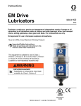
Instructions XC Impulse Lubricators 3A0416C EN Uses an external power impulse to control the discharge of grease or oil lubrication to all lubrication points of sliding- and roller bearings, drive- and transport chains, sliding guideways, open gears and seals. For professional use only. Not approved for use in European explosive atmospheres. 75 psi (0.5 MPa, 5 bar) Maximum Working Pressure Important Safety Instructions Read all warnings and instructions in this manual. Save these instructions. See page 4 for model information. Warnings The following warnings are for the setup, use, grounding, maintenance, and repair of this equipment. The exclamation point symbol alerts you to a general warning and the hazard symbols refer to procedure-specific risks. When these symbols appear in the body of this manual, refer back to these Warnings. Product-specific hazard symbols and warnings not covered in this section may appear throughout the body of this manual where applicable. WARNING WARNING ELECTRIC SHOCK HAZARD This equipment must be grounded. Improper grounding, setup, or usage of the system can cause electric shock. Turn off and disconnect power at main switch before disconnecting any cables and before servicing equipment. • Connect only to grounded power source. • All electrical wiring must be done by a qualified electrician and comply with all local codes and regulations. • FIRE AND EXPLOSION HAZARD When flammable fluids are present in the work area, such as gasoline and windshield wiper fluid, be aware that flammable fumes can ignite or explode. To help prevent fire and explosion: • • • • • • • • Use equipment only in well ventilated area. Eliminate all ignition sources, such as cigarettes and portable electric lamps. Keep work area free of debris, including rags and spilled or open containers of solvent and gasoline. Do not plug or unplug power cords or turn lights on or off when flammable fumes are present. Ground all equipment in the work area. Use only grounded hoses. If there is static sparking or you feel a shock, stop operation immediately. Do not use equipment until you identify and correct the problem. Keep a working fire extinguisher in the work area. TOXIC FLUID OR FUMES HAZARD Toxic fluids or fumes can cause serious injury or death if splashed in the eyes or on skin, inhaled, or swallowed. • Read MSDSs to know the specific hazards of the fluids you are using. • Store hazardous fluid in approved containers, and dispose of it according to applicable guidelines. 2 3A0416C WARNING WARNING PRESSURIZED EQUIPMENT HAZARD Fluid from the equipment, leaks, or ruptured components can splash in the eyes or on skin and cause serious injury. Follow the Pressure Relief Procedure before cleaning, checking, or servicing equipment. • Tighten all fluid connections before operating the equipment. • Check hoses, tubes, and couplings daily. Replace worn or damaged parts immediately. • EQUIPMENT MISUSE HAZARD Misuse can cause death or serious injury. • • • • • • • • • • • • 3A0416C Do not operate the unit when fatigued or under the influence of drugs or alcohol. Do not exceed the maximum working pressure or temperature rating of the lowest rated system component. See Technical Data in all equipment manuals. Use fluids and solvents that are compatible with equipment wetted parts. See Technical Data in all equipment manuals. Read fluid and solvent manufacturer’s warnings. For complete information about your material, request MSDS from distributor or retailer. Turn off all equipment and follow the Pressure Relief Procedure when equipment is not in use. Check equipment daily. Repair or replace worn or damaged parts immediately with genuine manufacturer’s replacement parts only. Do not alter or modify equipment. Do not puncture, open or take lubricator apart. Use equipment only for its intended purpose. Call your distributor for information. Route hoses and cables away from traffic areas, sharp edges, moving parts, and hot surfaces. Do not kink or over bend hoses or use hoses to pull equipment. Keep children and animals away from work area. Comply with all applicable safety regulations. 3 Models WARNING WARNING PERSONAL PROTECTIVE EQUIPMENT You must wear appropriate protective equipment when operating, servicing, or when in the operating area of the equipment to help protect you from serious injury, including eye injury, hearing loss, inhalation of toxic fumes, and burns. This equipment includes but is not limited to: • Protective eyewear, and hearing protection. • Respirators, protective clothing, and gloves as recommended by the fluid and solvent manufacturer. CALIFORNIA PROPOSITION 65 This product contains a chemical known to the State of California to cause cancer, birth defects or other reproductive harm. Wash hands after handling. Models Volume Output Application 120CC Bearing 24E089 120CC Construction 24E092 120CC Food Grade H1 24E091 120CC Milling 24E095 120CC Lithium EP1 24E088 120CC Lithium EP2 24E093 120CC Synthetic Industrial 24E094 120CC Ultra Spindle 24E098 250CC Bearing 24E097 250CC Construction 24E100 250CC Food Grade H1 24E099 250CC Milling Part No. 24E090 4 Volume Output Application 250CC Lithium EP1 24E096 250CC Lithium EP2 24E101 250CC Synthetic Industrial 24E102 250CC Ultra Spindle 24E082 Part No. 24E103 60CC Bearing 24E081 60CC Construction 24E084 60CC Food Grade H1 24E083 60CC Milling 24E087 60CC Lithium EP1 24E080 60CC Lithium EP2 24E085 60CC Synthetic Industrial 24E086 60CC Ultra Spindle 3A0416C Component Identification Component Identification A B A Plug B Lubrication Canister NOTE: Canister cannot be refilled. C † Drive Unit (Includes gear motor and circuit board) 3A0416C C D E F D LED function display E † Cover F † Cable with plug † Reusable parts 5 Component Identification Pin Assignment Pressure Relief Procedure Pin Assignment 1 2 3 4 Cable Color Signal brown current + white LED green digital blue current black LED red digital 1. Cover lubrication point (A) and lubricator (B) with a heavy rag to absorb any fluid that may leak out while loosening the adapter. 4 2. Carefully unscrew support adapter (D) from the lubrication point (A). 2 A 1 B C 3 D A B C D 6 Lubrication Point Lubrication Canister Drive Unit Support Adapter 3A0416C Component Identification Wiring Diagrams NOTICE Incorrect connection of the lubrication unit could destroy electronics. PLC Connection - One Output Signal 3A0416C 7 Component Identification PLC Connection - Two Output Signals 8 3A0416C Component Identification PLC Connection - Three Output Signals 3A0416C 9 Installation and Setup Installation and Setup Determining Correct Mounting Method NOTE: • Direct mounting should be used for lubrication points that are easily accessible. • Remote mounting is recommended if you answer YES to any of the questions below. 1. Is the ambient temperature at the lubrication point higher than +50°C (122°F)? 2. Is it necessary to remove protective screens, walls or other types of protection in order to reach the lubrication point? 3. Is the lubrication point exposed to high vibrations? 4. Is it difficult to access the lubrication point during operation of the machine? NOTE: • Be sure to use a lubricant cartridge that contains the same grease used in the application. • The best measurement results are achieved during operation. Checking the Counter Pressure 1. Clean the lubrication point to remove any potential contaminants. 2. Install reducers, extensions, grease line, etc. (if necessary). 3. Prime the grease line and all accessories with the same grease that is contained in the lubricator. (See Parts, page 22 for a complete list of available grease cartridges). 4. Remove the plug (A). 5. Is the lubrication point exposed to any of the following: • • • • water jets for high-pressure cleaning machines? corrosive chemicals? extreme temperature? falling materials? Preparing Lubricator for Installation The lubricator has a self-protection mechanism which shuts off the drive unit at counter pressures higher than 5 bar (72.5 psi). Most bearings require 0.5 - 2 bar (7.2 to 29 psi) pressure (without tubes, extensions, angles, etc.). Use the following procedure to check the counter pressure of the application prior to installation. 10 A 5. Install lubricator unit into adapter (B). B 6. Screw a pressure manometer into the lubrication point (dd) (FIG. 1, page 11). 3A0416C Installation and Setup A pressure manometer is a simple device that measures pressure output. To build a pressure manometer you need a pressure gage (aa), tee fitting (bb) and stop valve (cc). FIG. 1 shows a correctly assembled pressure manometer, connected to the lubricator and a lubrication point. dd ff bb cc aa ee FIG. 1 aa bb cc dd ee ff Pressure Gauge Tee Fitting Stop Valve Lube Point Lubricator ON / OFF Switch 7. Ensure the stop valve (cc) of the pressure manometer is open. 8. Attach lubricator and adapter (B) to the pressure manometer (aa - cc) and turn the switch to “ON” (ff) (FIG. 1). 9. Run the manometer for about 20 seconds. Observe the gauge and repeat this procedure until the pressure registered on the gauge stays constant. 10. To determine the counter pressure, wait approximately 5 minutes until the system has relaxed. Do one more discharge by turning the unit OFF; then ON again until it dispenses for no more than 5 seconds. 12. To disconnect lubricator from manometer, follow pressure relief procedure , page 6. NOTE: In this application, you will be disconnecting adapter (B) from manometer instead of lubrication point. NOTICE Do NOT disconnect lubricator from adapter (B). Screwing anything into lubricator a second time will damage self-sealing threads. 13. If the counter pressure is 5 bar (72.5 psi) or higher, flush the lubrication point with a grease gun. If the counter pressure does not decrease you may need a different lubricant or size lubricator canister. Contact Graco Customer service for assistance. Priming/Pre filling Fittings and Grease Lines All accessories and grease lines must be primed/pre filled. Without this priming/pre filling, the lubricator would first have to fill the accessories with lubricant. Example: A tube that is one meter long requires about 28 cm3 of lubricant. It would take the lubricator with a 12 month setting and an EM-120 grease canister about 3 months to fill this 1 meter tube. FIG. 2 illustrates one way to pre fill using a grease gun to dispense the grease. 11. Wait approximately 5 more minutes to make sure the system does not lose pressure and remains constant. FIG. 2 3A0416C 11 Installation and Setup Circuit Board Settings Function Display Red and green LED’s (Light Emitting Diodes) are on the circuit board and visible through the transparent cover. The following signals about operating conditions/malfunctions are displayed by these LED’s for the user: LED Signal Meaning Green Steady System functions OK Red Steady for less than 30 seconds with motor running Lubricator is discharging Red Steady signal for more than 30 seconds Malfunction / error Green and Red Steady signal Lubricator unit is empty. Change canister. Setting Dip Switches D 1. Unscrew and remove the cover of the drive unit. A 2. Use a small screwdriver or your finger to move dip switches to the desired position. Refer to Table 1. E B C FIG. 3 A B C D E 12 LED Red LED Green 4-way code switch Plug connection Circuit board 1 2 3 4 • Dip switches 1and 2 marked “TIME” are used to set the discharge amount per impulse. • Dip switches 3 and 4 marked “VOL” are used to set the lubrication canister size. If the 4-way code switch does not correspond to the actual size of the lubrication canister, it will lead to a wrong signal and over or under lubrication. 3A0416C Installation and Setup TABLE 1: Dip Switch Settings / Discharge Amounts in CC / Impulse • Amount of discharge in cc per impulse. • White square indicates position of dip switch. Lubrication Canister Size Dip Switch Position EM-60 3 4 EM-120 3 4 EM-250 3 4 VOL VOL VOL 2.11 2.11 2.11 1.06 1.06 1.06 0.53 0.53 0.53 0.26 0.26 0.26 ON 1 2 TIME ON 1 2 TIME ON 1 2 TIME ON 1 2 TIME NOTE: • As soon as power is supplied, the controller will discharge the set amount once. Power must be applied at least until the discharge has taken place (approximately 2 minutes). • In order to get another discharge cycle, the power must be interrupted for at least 15 seconds, and then supplied again. 3A0416C 13 Installation and Setup Selecting Mounting Location Installation Guidelines • For all metal to metal connections (i.e., extensions, reducers, etc.) make sure to use LOCTITE® 243* (semi-tight screw locking). *Loctite® is a registered trademark of the Loctite Corporation. • Before installing the lubricator, the lubrication points and any extensions must be adequately pre-lubricated with the same lubricant contained in the lubricator. A 400 gram lubricant cartridge for grease guns is available from Graco. See Parts, page 22 for a complete list of available lubricant cartridges. • Install one lubricator per lubrication point. • When oil is used for lubrication, a non-return valve (oil throttle) must be installed. This will prevent oil leakage from the lubricator. An oil throttle, part number 124102 is available from Graco. See Parts, page 22. • An oil-filled lubricator must be installed vertically (outlet down). • For horizontal mounting a bracket clip must be used to hold the lubricator in place. A horizontal clip bracket part number 124086 is available from Graco. See Parts, page 22 • For vertical installations always use a support adapter part number 124105 is available from Graco. See Parts, page 22. • The grease nozzle of the lubricator has a npt 1/4 inch male thread. If your application has a different thread you may need to use an adapter. See Parts, page 22 for a complete list of available adapters. • Do not overtighten the plastic thread of the lubricator. 14 Direct Mounting Installation Refer to FIG. 4 for examples of correct and incorrect direct mounting installations. Correct Incorrect FIG. 4 3A0416C Installation and Setup Remote Mounting Installations Grease Lubrication with Tube Refer to FIG. 5 - FIG. 7 for examples of correct remote mounting installations. • • Remote installations require a grease line. Graco recommends using a 5/16 inch flexible hose. A Select a position for the lubricator that is easy to access and protected from high-pressure water jets, falling materials, corrosive chemicals and extreme temperatures. B C D E F FIG. 5 A B C D E F Clip, 124086 Support adapter, 124105 Bracket, 124087 Tube connector (User supplied) Nylon tube (User supplied) Tube connections (User supplied) Must be at least 5/16 inch diameter tube. 3A0416C 15 Installation and Setup From-top-lubrication of a Chain with Oil A B C D E F G H J K A Clip, 124086 Support adapter, 124105 Bracket, 124087 Tube connector (User supplied) Nylon tube (User supplied) Tube connections (User supplied) Oil throttle, 124102* L-Bracket, 124098 Bulkhead mounting plate, 124099 Oil brush, 1”x 1.5”, 124090 *The non-return valve (oil throttle (G) should always be placed at the lowest point of the application. B Must be at least 5/16 inch diameter tube. C D E F G H J C K FIG. 6 16 3A0416C Installation and Setup Lubrication of Elevated Chain with Oil F E A B C G D FIG. 7 A B C D E F G Clip, 124086 Support adapter, 124105 Bracket, 124087 Tube connector (User supplied) Nylon tube (User supplied) Tube connections (User supplied) Oil throttle, 124102* *The non-return valve (oil throttle: G) should always be placed at the lowest point of the application. Must be at least 5/16 inch diameter tube. 3A0416C 17 Operation Installing Lubricator to Lubrication Point 7. Install lubricator unit into adapter (B). 1. Clean the lubrication point to remove any potential contaminants. 2. Verify the thread of the lubricator corresponds to the thread of the screw point. 3. Install reducers, extensions, grease line, etc. (if necessary). 4. Verify Dip Switches are correctly set. See Table 1, page 13. 5. Prime the grease line and all accessories with the same grease that is contained in the lubricator. (See Parts, page 22 for a complete list of available grease cartridges). 6. Remove the plug (A). B 8. Screw lubricator to lubrication point, hand tight only. NOTICE To ensure optimal lubrication: • Seal threads of all connecting parts with a suitable, standard sealant. • Mount oil filled lubricators properly with the outlet pointing down. • Never screw in the lubricator a second time or the self-sealing threads will be damaged. • For remote mounting installations, make sure bracket does not squeeze the lubrication canister as this could block the piston inside the canister. • The “VOL” switches 3 and 4 of the 4-way code switch match the correct size of the lubrication canister. • The “TIME” switches 1 and 2 of the 4-way code switch in the drive unit match the desired discharge impulse. • All components are properly assembled and screwed together hand tight. A Operation Before operation verify: • The lubricator does not have any visible damage. • The lubricator canister is filled with the requested grease or oil. • For oil filled lubrication canisters, an oil throttle must be attached. 18 3A0416C Changing the Lubrication Canister To begin the discharge: Plug power cable into lubricator (FIG. 8). . Changing the Lubrication Canister When the red and green LED light up at the same time, the lubrication canister is empty and should be replaced. NOTICE FIG. 8 During Operation: • Carry out regular performance checks. Check for possible leakages and the status of the lubricator. • Regularly monitor the fill-level of the transparent lubrication canister. The drive unit and circuit board must always be protected from moisture to prevent damaging these components. Always change the lubrication canister in a dry place. Removing Lubrication Canister 1. Unplug cable from lubricator (FIG. 9). FIG. 9 2. To disconnect adapter from lubrication point, follow pressure relief procedure provided on page 6. 3. Unscrew and completely remove adapter (B) from the lubricator. Adapter will be reused. 4. Unscrew cover from drive unit. 5. Remove drive unit from the lubrication control. 3A0416C B 19 Changing the Lubrication Canister Installing New Lubrication Canister 1. If a different size lubrication canister or discharge period is going to be used, change dip switches to reflect the new canister size and/or impulse change. See Table 1, page 13. 2. Place drive unit on top of new lubrication canister until the teeth of both pieces are locked. 3. Screw the cover of the drive unit onto the lubrication canister - hand tighten only. 4. Remove plug (A) from bottom of lubrication canister. FIG. 10 9. The control will wait for a pulse to start discharging. Lubrication Canister Disposal A 5. Install lubricator unit into adapter (B). 6. Screw lubricator into the lubrication point hand tighten only. DO NOT screw it in a second time. NOTICE Never screw in the lubricator a second time or the self-sealing threads will be damaged. Dispose of hazardous fluid in approved containers, and according to applicable guidelines. Read the MSDS to know the specific hazards of the fluids you are using. Storage When lubricators are not immediately installed, they must be stored in a dry, dust free, sunlight protected room, indoors. 7. For oil filled lubricators, make sure the lubricator is installed vertically (outlet pointing down). 8. Plug cable back into lubricator (FIG. 10). 20 3A0416C Troubleshooting Troubleshooting Malfunction Possible Cause Wrong cable connection Connect cable according to pin assignment (page 6). Check pin assignment. Break in cable Check voltage at plug. Attach new cable. No power supply Check power supply. Make sure there is sufficient power available for the number of lubricators used. Relay defect in machine Change relays. Lubricator does not function Lubricator signals “system functions OK” (green LED), although lubrication canister is empty Lubricator signals “system malfunctions” (red LED) Lubricator discharges too fast Lubricator signals “end of discharge” (red and green LED) although the unit is not empty Setting of VOL switch different than attached lubrication canister Partly filled lubrication canister was replaced by an almost empty lubrication canister Clogged tube and/or connection parts Counter pressure too high Wrong position of TIME switch Setting of VOL switch different than attached lubrication canister Almost empty lubrication canister was replaced with a partially filled canister Reset peg was not pushed down during assembly Lubricator does not discharge the correct amount 3A0416C Solution Dip switch setting was done incorrect Replace lubrication canister with a full lubrication canister Clean tube and connecting parts, then shut off and restart lubricator. Replace lubrication canister with a full lubrication canister Set TIME dip switches (1 and 2) to correct setting. Replace with full lubrication canister. Move drive unit a few teeth so reset peg is pushed down. Replace lubrication canister with a full lubrication canister Set TIME dip switches (1 and 2) to correct setting. 21 Parts Parts Miscellaneous Accessories Replacement Cap Part No. Description Qty. 123951 MOTOR, EM-XC 1 124279 HARNESS, cable, power 1 EM-XP/XC 124086 CLIP 1 124087 BRACKET, plastic 1 124089 BRUSH, pig hair, 1/4 fnpt - 3/4 1 124090 BRUSH, oil, 1 x 1.5 1 124091 BRUSH, oil, 1 x 2.4 1 124092 BRUSH, oil, 1 x 4 1 124093 BRUSH, link chain 1 124100 CLAMP, beam, 1” 1 124101 BRACKET, dual unit 1 124102 VALVE, check, oil throttle 124109 KIT, accessory, purge 1 124113 APPLICATOR, chain, felt 1 124114 BRUSH, nylon, 1/8 mnpt x 5/8 1 124115 BRUSH, nylon, 1/8 mnpt x 2 1 124116 KIT, SA heavy green 1 124119 PADDLE, open gear lube 1 Part No. 124110 124111 124112 Mounting Brackets Part No. 124094 124095 124096 124097 124098 124099 Description Qty. BRACKET, mounting, small 1 BRACKET, mounting, medium 1 BRACKET, mounting, large 1 BRACKET, mounting, flat 1 BRACKET, mounting, L 1 BRACKET, mounting, bulk1 head Description CAP, top CAP, full, 60-120 cc CAP, full, 250 cc Qty. 1 1 1 400 Gram Lubricant Cartridges Part No. Description Qty. 124176 CARTRIDGE, lubricant, Lith1 ium EP-2 124177 CARTRIDGE, lubricant, Con1 struction 124178 CARTRIDGE, lubricant, Bear1 ing 124179 CARTRIDGE, lubricant, Milling 1 124180 CARTRIDGE, lubricant, Food 1 Grade H1 124181 CARTRIDGE, lubricant, Syn1 thetic Industrial 124182 CARTRIDGE, lubricant, Ultra 1 Spindle 124183 CARTRIDGE, lubricant, Lith1 ium EP-1 Fitting Adapter Part No. Description Qty. 124105 ADAPTER, 1/4 fnpt x 1/4 mnpt 1 124106 ADAPTER, 1/4 fnpt x 1/8 mnpt 1 Pressure Relief Valve Part No. Description 124107 VALVE, relief, 1/8 m, 5 lb 124108 VALVE, relief, 1/8 m, 1 lb 22 Qty. 1 1 3A0416C Technical Data Refill Kits Part No. 24E582 24E583 24E584 24E585 24E586 24E587 24E588 24E589 24E590 24E591 24E592 24E593 Description Qty. KIT, refill, 60 cc, multi EP-2 1 KIT, refill, 60 cc, construction 1 KIT, refill, 60 cc, bearing 1 KIT, refill, 60 cc, mill 1 KIT, refill, 60 cc, food 1 KIT, refill, 60 cc, synthetic 1 KIT, refill, 60 cc, ultra 1 KIT, refill, 60 cc, multi EP-1 1 KIT, refill, 120 cc, multi EP-2 1 KIT, refill, 120 cc, construction 1 KIT, refill, 120 cc, bearing 1 KIT, refill, 120 cc, mill 1 Part No. 24E594 24E595 24E596 24E597 24E598 24E599 24E600 24E601 24E602 24E603 24E604 24E605 Description Qty. KIT, refill, 120 cc, food 1 KIT, refill, 120 cc, synthetic 1 KIT, refill, 120 cc, ultra 1 KIT, refill, 120 cc, multi EP-1 1 KIT, refill, 250 cc, multi EP-2 1 KIT, refill, 250 cc, construction 1 KIT, refill, 250 cc, bearing 1 KIT, refill, 250 cc, mill 1 KIT, refill, 250 cc, food 1 KIT, refill, 250 cc, synthetic 1 KIT, refill, 250 cc, ultra 1 KIT, refill, 250 cc, multi EP-1 1 Technical Data Cable Construction Conductor cross-section dimensions Power Supply Total current consumption Maximum output load Temperature range Maximum output pressure Storage Conditions Temperature Air born Noise Emission Cable is drag chain qualified, approved for the smallest bending radius 60 mm. 4 x 0.25 mm2 15 - 25 VDC (max 30 VDC, 5% residual ripple) for the duration of the actual lubricant discharge. 0.2 A (current at discharge can be up to 1.2 A). Pin 2 and 4 cannot exceed 400mA each -10°C to +50 °C (+14°F to +122°F) 5 bar (75 psi) Dry, dust free +20°C ± 5°C (+68°F ± 9°F) <70 dB(A)† Loctite® is a registered trademark of the Loctite Corporation. † Emission sound pressure level of the lubrication system measured at distance of 1 m / height 1.6 m. 3A0416C 23 Technical Data Weights and Measurements Type Volume cm3 fl. oz Diameter (D) Length (L) Weight (empty) mm in. mm in. kg lbs EM-60 60 2.03 71 2.8 142 5.60 0.310 0.68 EM-120 120 4.06 71 2.8 165 6.50 0.320 0.7 EM-250 250 8.45 71 2.8 215 8.46 0.360 0.79 1/4 npt D Lubrication Canister Drive L 24 3A0416C Notes Notes 3A0416C 25 Graco Standard Warranty Graco warrants all equipment referenced in this document which is manufactured by Graco and bearing its name to be free from defects in material and workmanship on the date of sale to the original purchaser for use. With the exception of any special, extended, or limited warranty published by Graco, Graco will, for a period of twelve months from the date of sale, repair or replace any part of the equipment determined by Graco to be defective. This warranty applies only when the equipment is installed, operated and maintained in accordance with Graco’s written recommendations. This warranty does not cover, and Graco shall not be liable for general wear and tear, or any malfunction, damage or wear caused by faulty installation, misapplication, abrasion, corrosion, inadequate or improper maintenance, negligence, accident, tampering, or substitution of non-Graco component parts. Nor shall Graco be liable for malfunction, damage or wear caused by the incompatibility of Graco equipment with structures, accessories, equipment or materials not supplied by Graco, or the improper design, manufacture, installation, operation or maintenance of structures, accessories, equipment or materials not supplied by Graco. This warranty is conditioned upon the prepaid return of the equipment claimed to be defective to an authorized Graco distributor for verification of the claimed defect. If the claimed defect is verified, Graco will repair or replace free of charge any defective parts. The equipment will be returned to the original purchaser transportation prepaid. If inspection of the equipment does not disclose any defect in material or workmanship, repairs will be made at a reasonable charge, which charges may include the costs of parts, labor, and transportation. THIS WARRANTY IS EXCLUSIVE, AND IS IN LIEU OF ANY OTHER WARRANTIES, EXPRESS OR IMPLIED, INCLUDING BUT NOT LIMITED TO WARRANTY OF MERCHANTABILITY OR WARRANTY OF FITNESS FOR A PARTICULAR PURPOSE. Graco’s sole obligation and buyer’s sole remedy for any breach of warranty shall be as set forth above. The buyer agrees that no other remedy (including, but not limited to, incidental or consequential damages for lost profits, lost sales, injury to person or property, or any other incidental or consequential loss) shall be available. Any action for breach of warranty must be brought within two (2) years of the date of sale. GRACO MAKES NO WARRANTY, AND DISCLAIMS ALL IMPLIED WARRANTIES OF MERCHANTABILITY AND FITNESS FOR A PARTICULAR PURPOSE, IN CONNECTION WITH ACCESSORIES, EQUIPMENT, MATERIALS OR COMPONENTS SOLD BUT NOT MANUFACTURED BY GRACO. These items sold, but not manufactured by Graco (such as electric motors, switches, hose, etc.), are subject to the warranty, if any, of their manufacturer. Graco will provide purchaser with reasonable assistance in making any claim for breach of these warranties. In no event will Graco be liable for indirect, incidental, special or consequential damages resulting from Graco supplying equipment hereunder, or the furnishing, performance, or use of any products or other goods sold hereto, whether due to a breach of contract, breach of warranty, the negligence of Graco, or otherwise. FOR GRACO CANADA CUSTOMERS The Parties acknowledge that they have required that the present document, as well as all documents, notices and legal proceedings entered into, given or instituted pursuant hereto or relating directly or indirectly hereto, be drawn up in English. Les parties reconnaissent avoir convenu que la rédaction du présente document sera en Anglais, ainsi que tous documents, avis et procédures judiciaires exécutés, donnés ou intentés, à la suite de ou en rapport, directement ou indirectement, avec les procédures concernées. Graco Information For the latest information about Graco products, visit www.graco.com. TO PLACE AN ORDER, contact your Graco distributor or call to identify the nearest distributor. Phone: 612-623-6928 or Toll Free: 1-800-533-9655, Fax: 612-378-3590 All written and visual data contained in this document reflects the latest product information available at the time of publication. Graco reserves the right to make changes at any time without notice. Original instructions. This manual contains English. MM 3A0416 Patent information: www.graco.com Graco Headquarters: Minneapolis International Offices: Belgium, China, Japan, Korea GRACO INC. P.O. BOX 1441 MINNEAPOLIS, MN 55440-1441 Copyright 2010, Graco Inc. is registered to ISO 9001 www.graco.com December 2014