1
Repair
3A0157B
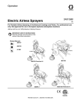
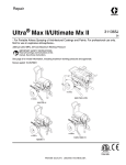
Electric Airless Sprayers
EN
For Portable Airless Spraying of Architectural Coatings and Paints. For professional use
only. Not approved for use in European explosive atmoshere locations.
3300 psi (227 bar, 22.7 MPa) Maximum Working Pressure
IMPORTANT SAFETY INSTRUCTIONS
Read all warnings and instructions in this
manual. Save these instructions.
Related Manuals:
3A0156
ti15034a
ti14838b
3A0158
Parts
311861
695/795
695/795 Premium Hi-Boy
ti15036b
ti15035b
MARK V
1095/1595 Premium Hi-Boy
Models:
Models:
Model
258719
258720
258722
258872
258873
258874
258876
258877
826124
826125
826127
Model
258723
258724
258878
258879
258881
258882
826128
826129
Model
258727
258728
258883
258884
258886
826130
826131
Model
258763
258764
258765
258766
826132
826133
826134
826135
Model
258729
Model
258730
258887
2
695 ULTRA MAX lIl
QuikReel
Hi-Boy
✓
✓
✓
Lo-Boy
✓
✓
✓
✓
✓
✓
✓
✓
✓
✓
✓
795 ULTRA MAX III
QuikReel
Hi-Boy
✓
✓
✓
✓
✓
Lo-Boy
✓
✓
✓
✓
✓
1095 ULTRA MAX III
QuikReel
Hi-Boy
✓
✓
✓
✓
✓
✓
✓
✓
✓
✓
✓
1595 ULTRA MAX III
QuikReel
Hi-Boy
✓
✓
✓
✓
✓
✓
✓
✓
✓
✓
✓
✓
MARK IV
QuikReel
Hi-Boy
✓
✓
MARK V
QuikReel
Hi-Boy
✓
✓
✓
✓
✓
✓
Lo-Boy
Lo-Boy
Lo-Boy
Lo-Boy
3A0157B
Table of Contents
Table of Contents
Models: . . . . . . . . . . . . . . . . . . . . . . . . . . . . . . . . . . . 2
Table of Contents . . . . . . . . . . . . . . . . . . . . . . . . . . 3
Warnings . . . . . . . . . . . . . . . . . . . . . . . . . . . . . . . . . 4
Component Identification . . . . . . . . . . . . . . . . . . . . 7
Pressure Relief Procedure . . . . . . . . . . . . . . . . . . . 8
Grounding . . . . . . . . . . . . . . . . . . . . . . . . . . . . . . . . 9
Power Requirements . . . . . . . . . . . . . . . . . . . . . . 9
Extension Cord . . . . . . . . . . . . . . . . . . . . . . . . . . 9
Pails . . . . . . . . . . . . . . . . . . . . . . . . . . . . . . . . . . 9
Troubleshooting . . . . . . . . . . . . . . . . . . . . . . . . . . . 10
Mechanical/Fluid Flow . . . . . . . . . . . . . . . . . . . . 10
Electrical . . . . . . . . . . . . . . . . . . . . . . . . . . . . . . 13
240 VAC and 110 VAC Motor Control Board . . . 21
240 VAC Filter Board . . . . . . . . . . . . . . . . . . . . 23
Pressure Adjust Potentiometer . . . . . . . . . . . . . 24
Pressure Control Transducer . . . . . . . . . . . . . . 25
Notes . . . . . . . . . . . . . . . . . . . . . . . . . . . . . . . . . . . . 27
Drive and Bearing Housing Replacement . . . . . . 28
Disassembly . . . . . . . . . . . . . . . . . . . . . . . . . . . 28
Assembly . . . . . . . . . . . . . . . . . . . . . . . . . . . . . . 28
Motor Replacement . . . . . . . . . . . . . . . . . . . . . . . . 30
Removal . . . . . . . . . . . . . . . . . . . . . . . . . . . . . . 30
Installation . . . . . . . . . . . . . . . . . . . . . . . . . . . . . 30
3A0157B
Displacement Pump Replacement for
695/795/Mark IV . . . . . . . . . . . . . . . . . . . . . . . . . . .
Removal . . . . . . . . . . . . . . . . . . . . . . . . . . . . . .
Installation . . . . . . . . . . . . . . . . . . . . . . . . . . . . .
Displacement Pump Replacement
1095/1595/Mark V . . . . . . . . . . . . . . . . . . . . . . . . . .
Removal . . . . . . . . . . . . . . . . . . . . . . . . . . . . . .
Installation . . . . . . . . . . . . . . . . . . . . . . . . . . . . .
Hose Reel . . . . . . . . . . . . . . . . . . . . . . . . . . . . . . . .
Removal . . . . . . . . . . . . . . . . . . . . . . . . . . . . . .
Installation . . . . . . . . . . . . . . . . . . . . . . . . . . . . .
Reed Switch Replacement . . . . . . . . . . . . . . . . . .
Removal . . . . . . . . . . . . . . . . . . . . . . . . . . . . . .
Installation . . . . . . . . . . . . . . . . . . . . . . . . . . . . .
Wiring Diagram . . . . . . . . . . . . . . . . . . . . . . . . . . .
120V Models: . . . . . . . . . . . . . . . . . . . . . . . . . .
120V Models (with 15/20 Amp Switch): . . . . . .
240V Models: . . . . . . . . . . . . . . . . . . . . . . . . . .
Notes . . . . . . . . . . . . . . . . . . . . . . . . . . . . . . . . . . . .
Graco Standard Warranty . . . . . . . . . . . . . . . . . . .
32
32
33
34
34
35
37
37
38
39
39
39
40
40
41
42
43
44
3
Warnings
Warnings
The following warnings are for the setup, use, grounding, maintenance and repair of this equipment. The exclamation
point symbol alerts you to a general warning and the hazard symbol refers to procedure-specific risks. Refer back to
these warnings. Additional, product-specific warnings may be found throughout the body of this manual where applicable.
WARNING
GROUNDING
This product must be grounded. In the event of an electrical short circuit, grounding reduces the risk of electric shock by providing an escape wire for the electric current. This product is equipped with a cord having a
grounding wire with an appropriate grounding plug. The plug must be plugged into an outlet that is properly
installed and grounded in accordance with all local codes and ordinances.
•
•
•
•
•
•
Improper installation of the grounding plug is able to result in a risk of electric shock.
When repair or replacement of the cord or plug is required, do not connect the grounding wire to either
flat blade terminal.
The wire with insulation having an outer surface that is green with or without yellow stripes is the grounding wire.
Check with a qualified electrician or serviceman when the grounding instructions are not completely
understood, or when in doubt as to whether the product is properly grounded.
Do not modify the plug provided; if it does not fit the outlet, have the proper outlet installed by a qualified
electrician.
This product is for use on a nominal 120V circuit and has a grounding plug similar to the plug illustrated
in the figure below.
• Only connect the product to an outlet having the same configuration as the plug.
• Do not use an adapter with this product.
Extension Cords:
• Use only a 3-wire extension cord that has a 3-blade grounding plug and a 3-slot receptacle that accepts
the plug on the product.
• Make sure your extension cord is not damaged. If an extension cord is necessary, use 12 AWG
(2.5 mm2) minimum to carry the current that the product draws.
• An undersized cord results in a drop in line voltage and loss of power and overheating.
4
3A0157B
Warnings
WARNING
FIRE AND EXPLOSION HAZARD
Flammable fumes, such as solvent and paint fumes, in work area can ignite or explode. To help prevent fire
and explosion:
•
•
•
•
•
•
•
•
•
•
•
•
•
Do not spray flammable or combustible materials near an open flame or sources of ignition such as cigarettes, motors, and electrical equipment.
Paint or solvent flowing through the equipment is able to result in static electricity. Static electricity creates a risk of fire or explosion in the presence of paint or solvent fumes. All parts of the spray system,
including the pump, hose assembly, spray gun, and objects in and around the spray area shall be properly grounded to protect against static discharge and sparks. Use Graco conductive or grounded
high-pressure airless paint sprayer hoses.
Do not clean with materials having flash points lower than 70° F (21° C). Use water-based material or
mineral spirits-type material only. For complete information about your fluid, request the MSDS from the
fluid distributor or retailer.
Verify that all containers and collection systems are grounded to prevent static discharge.
Connect to a grounded outlet and use grounded extensions cords. Do not use a 3-to-2 adapter.
Do not use a paint or a solvent containing halogenated hydrocarbons.
Keep spray area well-ventilated. Keep a good supply of fresh air moving through the area. Keep pump
assembly in a well ventilated area. Do not spray pump assembly.
Do not smoke in the spray area.
Do not operate light switches, engines, or similar spark producing products in the spray area.
Keep area clean and free of paint or solvent containers, rags, and other flammable materials.
Know the contents of the paints and solvents being sprayed. Read all Material Safety Data Sheets
(MSDS) and container labels provided with the paints and solvents. Follow the paint and solvents manufacturer’s safety instructions.
Fire extinguisher equipment shall be present and working.
Sprayer generates sparks. When flammable liquid is used in or near the sprayer or for flushing or cleaning, keep sprayer at least 20 feet (6 m) away from explosive vapors.
SKIN INJECTION HAZARD
• Do not aim the gun at, or spray any person or animal.
• Keep hands and other body parts away from the discharge. For example, do not try to stop leaks with
any part of the body.
• Always use the nozzle tip guard. Do not spray without nozzle tip guard in place.
• Use Graco nozzle tips.
• Use caution when cleaning and changing nozzle tips. in the case where the nozzle tip clogs while spraying, follow the Pressure Relief Procedure for turning off the unit and relieving the pressure before
removing the nozzle tip to clean.
• Do not leave the unit energized or under pressure while unattended. When the unit is not in use, turn off
the unit and follow the Pressure Relief Procedure for turning off the unit.
• High-pressure spray is able to inject toxins into the body and cause serious bodily injury. In the event
that injection occurs, get immediate surgical treatment.
• Check hoses and parts for signs of damage. Replace any damaged hoses or parts.
• This system is capable of producing 3300 psi. Use Graco replacement parts or accessories that are
rated a minimum of 3300 psi.
• Always engage the trigger lock when not spraying. Verify the trigger lock is functioning properly.
• Verify that all connections are secure before operating the unit.
Know how to stop the unit and bleed pressure quickly. Be thoroughly familiar with the controls.
3A0157B
5
Warnings
WARNING
EQUIPMENT MISUSE HAZARD
Misuse can cause death or serious injury.
•
•
•
•
•
•
•
•
•
Always wear appropriate gloves, eye protection, and a respirator or mask when painting.
Do not operate or spray near children. Keep children away from equipment at all times.
Do not overreach or stand on an unstable support. Keep effective footing and balance at all times.
Stay alert and watch what you are doing.
Do not leave the unit energized or under pressure while unattended. When the unit is not in use, turn off
the unit and follow the Pressure Relief Procedure for turning off the unit.
Do not operate the unit when fatigued or under the influence of drugs or alcohol.
Do not kink or over-bend the hose.
Do not expose the hose to temperatures or to pressures in excess of those specified by Graco.
Do not use the hose as a strength member to pull or lift the equipment.
ELECTRIC SHOCK HAZARD
This equipment must be grounded. Improper grounding, setup, or usage of the system can cause electric
shock.
• Turn off and disconnect power at main switch before disconnecting any cables and before servicing
equipment.
• Connect only to grounded power source.
• All electrical wiring must be done by a qualified electrician and comply with all local codes and regulations.
PRESSURIZED ALUMINUM PARTS HAZARD
Use of fluids that are incompatible with aluminum in pressurized equipment can cause serious chemical
reaction and equipment rupture. Failure to follow this warning can result in death, serious injury, or property
damage.
• Do not use 1,1,1-trichloroethane, methylene chloride, other halogenated hydrocarbon solvents or fluids
containing such solvents.
• Many other fluids may contain chemicals that can react with aluminum. Contact your material supplier
for compatibility.
MOVING PARTS HAZARD
Moving parts can pinch, cut or amputate fingers and other body parts.
• Keep clear of moving parts.
• Do not operate equipment with protective guards or covers removed.
• Pressurized equipment can start without warning. Before checking, moving, or servicing equipment, follow the Pressure Relief Procedure and disconnect all power sources.
PERSONAL PROTECTIVE EQUIPMENT
You must wear appropriate protective equipment when operating, servicing, or when in the operating area of
the equipment to help protect you from serious injury, including eye injury, hearing loss, inhalation of toxic
fumes, and burns. This equipment includes but is not limited to:
• Protective eyewear, and hearing protection.
• Respirators, protective clothing, and gloves as recommended by the fluid and solvent manufacturer.
6
3A0157B
Component Identification
Component Identification
13.
12.
1.
2.
11.
3.
4.
5.
6.
7.
8.
9.
10.
ti14839b
1
Premium Digital Display
2
ON/OFF switch
3
WatchDog™ Switch (not available on Mark V)
4
Pressure Control
5
Prime / Spray Valve
6
Filter
7
Siphon Tube
8
Pump
9
Bearing Housing / ProConnect™
10
Drain Tube
11
Trigger Lock
12
Model/serial tag
13
Hose Reel
3A0157B
7
Pressure Relief Procedure
Pressure Relief Procedure
1. Turn power OFF. Wait 7 seconds for power to
dissipate.
ti4265a
2. Lock gun trigger safety. Remove guard and
SwitchTip.
ti10166a
ti2769a
3. Turn pressure to lowest setting. Trigger gun to
relieve pressure.
-
ti14841a
4. Put drain tube in pail. Turn prime valve down to
DRAIN position.
ti2595a
8
ti14842a
3A0157B
Grounding
Grounding
The sprayer must be grounded. Grounding reduces the
risk of static and electric shock by providing an escape
wire for the electrical current due to static build up or in
the event of a short circuit.
The sprayer cord includes a grounding wire with an
appropriate grounding contact.
The plug must be plugged into an outlet that is properly
installed and grounded in accordance with all local
codes and ordinances.
Pails
Solvent and oil/based fluids: follow local code. Use
only conductive metal pails, placed on a grounded surface such as concrete.
Do not place pail on a nonconductive surface such as
paper or cardboard which interrupts grounding continuity.
ti2810a
ti5850a
ti2810a
ti4297a
Do not modify plug! Tampering with the plug will result in
a voided warranty. If plug will not fit in outlet, have
grounded outlet installed by a qualified electrician. Do
not use an adapter.
Grounding a metal pail: connect a ground wire to the
pail by clamping one end to pail and other end to a true
earth ground.
Power Requirements
•
100-120V units require 100-120 VAC, 50/60 Hz,
15A, 1 phase.
•
230V units require 230 VAC, 50/60 HZ, 10A,
1 phase.
Extension Cord
Use an extension cord with an undamaged ground contact. If an extension cord is necessary, use a 3-wire, 12
AWG (2.5 mm2) minimum.
ti14840a
To maintain grounding continuity when flushing or
relieving pressure: hold metal part of spray gun firmly
to side of a grounded metal pail. Then trigger gun.
Ground
ti13243a
120 volt plug
3A0157B
9
Troubleshooting
Troubleshooting
Mechanical/Fluid Flow
Perform Pressure Relief Procedure; page 8.
TYPE OF PROBLEM
WHAT TO CHECK
If check is OK, go to next check
WHAT TO DO
When check is not OK, refer to this column
E=XX is displayed
1. Fault condition exists
1. Determine fault correction from table,
page 13.
False tripping of WatchDog
system. EMPTY is displayed. Pump does not
run.
1. Operating conditions out of
WatchDog parameters. Pump
output is low, see below.
1. Turn pressure down. Refer to operation
manual for adjusting. Operate without
WatchDog active; see operation manual.
10
3A0157B
Troubleshooting
TYPE OF PROBLEM
Pump output is low
WHAT TO CHECK
If check is OK, go to next check
WHAT TO DO
When check is not OK, refer to this column
1. Spray tip worn
1. Follow Pressure Relief Procedure on
page 8, then replace tip. See your separate gun or tip manual.
2. Spray tip clogged
2. Relieve pressure. Check and clean spray
tip.
3. Paint supply
3. Refill and reprime pump.
4. Intake strainer clogged
4. Remove and clean, then reinstall
5. Intake valve ball and piston ball
are not seating properly
5. Remove intake valve and clean. Check
balls and seats for nicks; replace if necessary; see pump manual 310643 or
310894. Strain paint before using to
remove particles that could clog pump.
6. Suction hose connections
6. Tighten any loose connections. Check for
missing or damaged seals.
7. Fluid filter, tip filter, or tip is
clogged or dirty.
7. Clean filter; see operation manual.
8. Prime valve leaking
8. Relieve pressure. Repair prime valve.
9. Verify pump does not continue to 9. Service pump; see pump manual 310643
or 310894.
stroke when gun trigger is
released. (Prime valve not leaking.)
10. Leaking around throat packing
nut which may indicate worn or
damaged packings.
10. Replace packings; see pump manual. Also
check piston valve seat for hardened paint
or nicks and replace if necessary. Tighten
packing nut/wet-cup.
11. Pump rod damage
11. Repair pump. See pump manual 310643
or 310894.
12. Low stall pressure
12. Turn pressure knob fully clockwise. Make
sure pressure control knob is properly
installed to allow full clockwise position. If
problem persists, replace pressure transducer.
13. Piston packings are worn or
damaged
13. Replace packings; see pump manual
310643 or 310894.
14. O-ring in pump is worn or damaged
14. Replace o-ring; see pump manual 310643
or 310894.
15. Intake valve ball is packed with
material
15. Clean intake valve; see pump manual
310643 or 310894.
16. Pressure setting is too low
16. Increase pressure; see pump manual
310643 or 310894.
17. Large pressure drop in hose with 17. Use larger diameter hose and/or reduce
heavy materials
overall length of hose. Use of more than
100 ft of 1/4 in. hose significantly reduces
performance of sprayer. Use 3/8 in. hose
for optimum performance (50 ft minimum).
3A0157B
11
Troubleshooting
TYPE OF PROBLEM
Motor runs but pump does
not stroke
Excessive paint leakage
into throat packing nut
Fluid is spitting from gun
Pump is difficult to prime
WHAT TO CHECK
If check is OK, go to next check
WHAT TO DO
When check is not OK, refer to this column
1. Displacement pump pin (32)
damaged or missing; see pump
manual 310643 or 310894.
1. Replace pump pin if missing. Be sure
retainer spring (31) is fully in groove all
around connecting rod; see pump manual
310643 or 310894.
2. Connecting rod assembly (43)
damaged; see pump manual
310643 or 310894.
2. Replace connecting rod assembly; see
pump manual 310643 or 310894.
3. Gears or drive housing damaged, page 28.
3. Inspect drive housing assembly and gears
for damage and replace if necessary; see
pump manual 310643 or 310894.
1. Throat packing nut is loose
1. Remove throat packing nut spacer.
Tighten throat packing nut just enough to
stop leakage.
2. Throat packings are worn or
damaged
2. Replace packings; see pump manual
310643 or 310894.
3. Displacement rod is worn or
damaged
3. Replace rod; see pump manual 310643 or
310894.
1. Air in pump or hose
1. Check and tighten all fluid connections.
Cycle pump as slowly as possible during
priming.
2. Tip is partially clogged
2. Clear tip; see tip guard manual 309640.
3. Fluid supply is low or empty
3. Refill fluid supply. Prime pump; see pump
manual 310643 or 310894. Check fluid
supply often to prevent running pump dry.
1. Air in pump or hose
1. Check and tighten all fluid connections.
Cycle pump as slowly as possible during
priming.
2. Intake valve is leaking
2. Clean intake valve. Be sure ball seat is not
nicked or worn and that ball seats well.
Reassemble valve.
3. Pump packings are worn
3. Replace pump packings; see pump manual 310643 or 310894.
4. Paint is too thick
4. Thin the paint according to supplier recommendations.
No display, sprayer operates 1. Display is damaged or has bad
connection
12
1. Check connections. Replace display.
3A0157B
Troubleshooting
Electrical
Symptom: Sprayer does not run or stops running.
Perform Pressure Relief Procedure; page 8.
•
Plug sprayer into correct voltage, grounded outlet
•
Set power switch OFF for 30 seconds and then ON
again (this ensures sprayer is in normal run mode).
•
Turn pressure control knob clockwise 1/2 turn
•
View digital display
TYPE OF PROBLEM
Sprayer does not run at all
To avoid electrical shock or moving parts hazards when
covers are removed for troubleshooting, wait 30 seconds after unplugging power cord for stored electricity
to dissipate. Keep clear of electrical and moving parts
during troubleshooting procedures.
WARNING
If no digital display is available, use control
board status light to troubleshoot problems: Turn ON/OFF switch OFF, remove
control cover and then turn power back
ON. Observe status light. Blinking LED total count equals digital error code i.e., two
blinks equals E=02.
WHAT TO CHECK
HOW TO CHECK
See flow chart, page 19.
Digital display is blank
Control board status light never
lights
Sprayer does not run at all
Digital display shows E=02
Control board status light blinks
2 times repeatedly
3A0157B
Check transducer or transducer
connections
1.
Make sure there is no pressure in the system (see
Pressure Relief Procedure, page 8). Check fluid
path for clogs, such as clogged filter.
2.
Use airless paint spray hose with no metal braid
1/4 in. x 50 ft minimum. Smaller hose or metal braid
hose may result in high-pressure spikes.
3.
Set sprayer to OFF and disconnect power to
sprayer.
4.
Check transducer and connections to control board.
5.
Disconnect transducer from control board socket.
Check that transducer and control board contacts
are clean and secure.
6.
Reconnect transducer to control board socket.
Connect power, set sprayer ON and control knob
1/2 turn clockwise. If sprayer does not run properly,
set sprayer to OFF and go to next step.
7.
Install new transducer. Connect power, set sprayer
ON and control knob 1/2 turn clockwise. Replace
control board if sprayer does not run properly.
13
Troubleshooting
TYPE OF PROBLEM
Sprayer does not run at all
Digital display shows E=03
Control board status light blinks
3 times repeatedly
14
WHAT TO CHECK
Check transducer or transducer
connections (control board is not
detecting a pressure signal).
HOW TO CHECK
1.
Set sprayer to OFF and disconnect power to
sprayer.
2.
Check transducer and connections to control board.
3.
Disconnect transducer from control board socket.
Check to see if transducer and control board
contacts are clean and secure.
4.
Reconnect transducer to control board socket.
Connect power, set sprayer ON and control knob
to 1/2 turn clockwise. If sprayer does not run,
set sprayer to OFF and go to next step.
5.
Connect a confirmed working transducer to control
board socket.
6.
Set sprayer ON and control knob to 1/2 turn
clockwise. If sprayer runs, install new transducer.
Replace control board if sprayer does not run.
7.
Check transducer resistance with ohmmeter (less
than 9k ohm between red and black wires and 3-6k
ohm between green and yellow wires).
3A0157B
Troubleshooting
TYPE OF PROBLEM
Sprayer does not run at all
Digital display shows E=05
WHAT TO CHECK
HOW TO CHECK
Control is commanding motor to run 1.
but motor shaft does not rotate.
Possibly locked rotor condition, an
open connection exists between
2.
motor and control, there is a
problem with motor or control board,
or motor amp draw is excessive.
3.
Control board status light blinks
5 times repeatedly
Remove pump and try to run sprayer. If motor runs,
check for locked or frozen pump or drive train.
If sprayer does not run, continue to step 2.
Set sprayer to OFF and disconnect power to
sprayer.
Disconnect motor connector(s) from control board
socket(s). Check that motor connector and control
board contacts are clean and secure. If contacts
are clean and secure, continue to step 4.
4.
Set sprayer to OFF and spin motor fan 1/2 turn.
Restart sprayer. If sprayer runs, replace control
board. If sprayer does not run, continue to step 5.
5.
Perform Spin Test: Test at large 4-pin motor field
connector. Disconnect fluid pump from sprayer. Test
motor by placing a jumper across pins 1 & 2. Rotate
motor fan at about 2 revolutions per second. A cogging
resistance to motion should be felt at the fan.
The motor should be replaced if no resistance is felt.
Repeat for pin combinations 1 & 3 and 2 & 3. Pin 4
(the green wire) is not used in this test. If all spin test
is positive, continue to step 6.
Green Blue Red Black
STEP 1:
Green Blue Red Black
STEP 2:
Green Blue Red Black
STEP 3:
3A0157B
15
Troubleshooting
TYPE OF PROBLEM
Sprayer does not run at all
Digital display shows E=05
Control board status light blinks
5 times repeatedly
WHAT TO CHECK
Control is commanding motor to run 6.
but motor shaft does not rotate.
Possibly locked rotor condition,
an open connection exists between
motor and control, there is a problem
with motor or control board, or
7.
motor amp draw is excessive.
HOW TO CHECK
Perform Field Short Test: Test at large 4-pin motor
field connector. There should not be continuity from
pin 4, the ground wire, and any of the remaining
3 pins. If motor field connector tests fail,
replace motor.
Check Motor Thermal Switch: Unplug thermal
wires. Set meter to ohms. Meter should read the
proper resistance for each model (see table below).
-
ti13140a
Resistance Table:
16
695
0 ohms
795
2k ohms
1095
3.9k ohms
1595
6.2k ohms
MARK IV
2k ohms
MARK V 120V
6.2k ohms
MARK V 240V
3.9k ohms
3A0157B
Troubleshooting
TYPE OF PROBLEM
WHAT TO CHECK
HOW TO CHECK
Sprayer does not run at all
Allow sprayer to cool. If sprayer runs NOTE: Motor must be cooled down for the test.
when
cool, correct cause of
Digital display shows E=06
1. Check thermal device connector (yellow wires)
overheating. Keep sprayer in cooler
at control board.
location with good ventilation. Make
sure motor air intake is not blocked. 2. Disconnect thermal device connector from control
If sprayer still does not run, follow
board socket. Make sure contacts are clean and
Step
1.
secure.
Control board status light blinks
6 times repeatedly
Measure resistance of the thermal device. If reading
is not correct, replace motor.
Check Motor Thermal Switch: Unplug thermal
wires. Set meter to ohms. Meter should read the
proper resistance for each model (see table below).
-
Resistance Table:
ti13140a
Sprayer does not run at all
Digital display shows E=09
Control board status light blinks
9 times repeatedly
3A0157B
Check the connections. Control
is not receiving a motor position
sensor signal
695
0 ohms
795
2k ohms
1095
3.9k ohms
1595
6.2k ohms
MARK IV
2k ohms
MARK V 120V
6.2k ohms
MARK V 240V
3.9k ohms
3.
Reconnect thermal device connector to control
board socket. Connect power, turn sprayer ON and
control knob 1/2 turn clockwise. If sprayer does not
run, replace control board.
1.
Turn power OFF.
2.
Disconnect motor position sensor and inspect for
damage at connectors.
3.
Reconnect sensor.
4.
Turn power ON. If error continues, replace motor.
17
Troubleshooting
TYPE OF PROBLEM
Sprayer does not run at all
Digital display shows E=10
WHAT TO CHECK
HOW TO CHECK
Check to see if control board is over 1.
heating.
2.
Control board status light blinks
10 times repeatedly
Make sure motor air intake is not blocked.
Make sure fan has not failed.
3.
Make sure control board is properly connected
to back plate and that conductive thermal paste
is used on power components.
4.
Replace control board.
5.
Replace motor.
Sprayer Will Not Shut Off
1. Perform Pressure Relief Procedure; page 8. Leave
prime valve open and power switch OFF.
2. Remove control box cover so the control board
status light can be viewed if available.
Troubleshooting Procedure
Plumb pressure gauge into paint
hose, plug sprayer in, and turn power
switch ON. Does sprayer reach or
exceed its maximum pressure?
NO
Mechanical problem: See the proper
fluid pump manual for the sprayer for
further trouble shooting procedures.
YES
Unplug the transducer from control
board. Does motor stop running?
NO
Replace the control board.
YES
Bad transducer. Replace and test
with a new one.
18
3A0157B
Troubleshooting
Sprayer Will Not Run
(See following page for steps)
Remove control box cover. Turn
sprayer ON. Observe control
board status light on control board
(see page 13).
No light
Once
Normal operation
Light on
Continuously
Control board
commanding
motor to run
Flashing
See Error Code
section for further
troubleshooting
See Step 1. Do
you have over
100 AC volts (200
for 220V units)?
NO
See Step 2. Do
you have over
100 AC volts?
NO
Repair or
replace
power cord.
YES
Replace the
ON/OFF switch.
YES
See Step 3. Is the
proper reading
present through the
thermal switch
wires?.
NO
If motor is hot, let cool and
retest. If Step 4 still shows
incorrect resistance, replace
motor. The motor has
a defective thermal device.
NO
Connect a test
transducer to the
board. Does the
motor run?
YES
See step 4. Does
the motor run?
NO
YES
YES
Replace
potentiometer.
Pressure switch.
3A0157B
Replace the
control board.
Replace the
transducer
19
Troubleshooting
V
-
110-120 AC
V
-
STEP 2:
Plug power cord in
and turn switch ON.
Connect wires to
control board and
on/off switch. Turn
meter to AC Volts.
100k ohm
-
-
Thermal
Switch
Black
Black
STEP 3:
Check motor thermistor.
Unplug yellow wires. Meter
should read according to
Resistance Table on page 17.
NOTE: Motor should be cool
during reading.
-
+
110-120 AC
STEP 1:
Plug power cord in
and turn switch ON.
Connect wires to
control board and
on/off switch. Turn
meter to AC Volts.
Yellow
Black
Power Cord
White
+
On/Off
Switch
+
On/Off
Switch
White
Black
Control
Board
Motor
Control
Board
Power Cord
Control
Board
Thermal
Switch
To Optional
Display
Potentiometer
Motor
STEP 4:
Plug power cord
in and turn switch
ON. Disconnect
potentiometer.
Pressure
Transducer
Black
AutoClean
Motor
Leads
Motor
Sensor
Leads
Control
Board
WatchDog Switch:
On - Open
Off - Closed
Neutral
Black
Switch:
15 Amp - Closed
20 Amp - Open
Green/Ground
On/Off
Switch
Black
White
Black +
GFI Filter Coil
Green/Ground
20
Power Plug
3A0157B
Troubleshooting
240 VAC and 110 VAC Motor Control Board
Removal
Installation
1. Use acetone or equivalent cleaner to thoroughly
remove thermal paste from pockets on powerbar.
Perform Pressure Relief Procedure; page 8. Wait 5
minutes before servicing.
1. Remove Motor Shroud (for units equipped with
Hose Reel only):
ti14695a
a. Remove bolts from motor shroud.
b.
Remove pressure tube from sprayer.
c.
Remove bottom screw from toolbox.
2. Apply new thermal paste into both pockets of powerbar.
d. Loosen (but do not remove) four nuts on shelf.
Carefully slide shelf forward.
e. Remove shroud.
f.
Slide shelf back and tighten four nuts on shelf.
2. Remove all four screws (38) and cover (96).
ti14693a
3. Disconnect display connector (A) from motor control
board (52).
4. Remove bottom two screws (39). disconnect potentiometer connector (C) from motor control board
(52). Disconnect power cord connectors (D) and filter board connectors (J) from ON/OFF switch (33)
and remove control panel (68).
5. Disconnect WatchDog switch connector (X) and
reed switch connector (L) from motor control board.
3. Replace two inner screws to control board and
torque to 17 in-lb (1 N•m).
ti14696a
6. Disconnect motor control board power connectors
(K) from filter board (146).
7. Remove top two screws (39) and control box (61).
4. Replace six outer screws to control board and
torque to 11 in-lb (1.25 N•m).
8. Disconnect transducer connector (E) from motor
control board.
9. Disconnect motor connectors (F, G and H).
10. Remove six screws (27), two screws (102) and control board.
3A0157B
ti14697a
21
Troubleshooting
5. Make switch dip switch is moved to the left (toward
inside of board). See Wiring Diagram, page 40.
6. Connect motor connectors (F, G and H) and install
into baffle.
7. Connect transducer connector (E) to motor control
board.
13. Install control panel (68) with two screws (39).
14. Connect display connector (A) to motor control
board (52).
15. Install cover (96) with four screws (38)
16. Install Motor Shroud (for units equipped with Hose
Reel only):
8. Connect motor control board power connectors (K)
to filter board (146).
a. Loosen (but do not remove) four nuts on shelf
and slide shelf forward.
9. Install control box (61) with top two screws (39).
b.
Replace shroud.
10. Connect filter board power connectors (J) and
power cord connectors (D) to ON/OFF switch (33).
c.
Slide shelf back and tighten four nuts on shelf.
11. Connect potentiometer connector (C) to motor control board.
e. Replace pressure tube from sprayer.
d. Replace bottom screw from toolbox and tighten.
f.
12. Connect WatchDog switch (X) and reed switch connector (L) to motor control board.
Replace bolts from motor shroud.
5
52
146
61
A
27
C
96
J
38
E
33 D
39
52
E
80
20
68
82
82
115
39
67
34
X
Fast Flush
1595
MARK V
ti14891a
22
3A0157B
Troubleshooting
240 VAC Filter Board
6. Remove four screws (163) from filter board (146).
Installation
1. Install filter board (146) with four screws (163).
Perform Pressure Relief Procedure; page 8.
2. Connect motor control board power connectors (K)
to filter board (146).
Removal
3. Connect filter board power connectors (J) to top two
terminals of ON/OFF switch (33) and power cord
connectors (D) to bottom two terminals of ON/OFF
switch.
1. Remove four screws (38) and cover (96).
2. Disconnect display connector (A) from motor control
board (52).
4. Connect potentiometer connector (C) to motor control board (52).
3. Remove bottom two screws (39). disconnect potentiometer connector (C) from motor control board
(52). Disconnect power cord connectors (D) and filter board connectors (J) from ON/OFF switch (33)
and remove control panel (68).
5. Connect WatchDog switch (X) and reed switch connector (L) to motor control board.
6. Install control panel (68) with two screws (39).
4. Disconnect WatchDog switch connector (X) and
reed switch connector (L) from motor control board.
7. Connect display connector (A) to motor control
board (52).
5. Disconnect motor control board power connectors
(K) from filter board (146).
240 VAC
8. Install cover (96) with four screws (38).
5
F
H
52
26
G
52
146
61 K
A
C
163
A
96
38
J
A
A
E
33
39
E
C
39
82
82
34
68
L
80
20
67
ti14890a
115
X
3A0157B
23
Troubleshooting
Pressure Adjust Potentiometer
Removal
Installation
1. Install gasket (115), nut and potentiometer (82) on
control panel (68). Torque nut to 30-35 in-lb (3.25 4.0 N•m).
68
Perform Pressure Relief Procedure; page 8. Wait 5
minutes before servicing.
1. Remove four screws (38) and cover (96).
82
82
115
96
ti13674a
38
2. Rotate new potentiometer shaft to highest pressure
setting (fully clockwise) and install knob (34). Use
allen wrench to tighten two screws on knob.
ti13493a
2. Remove two screws and control panel.
34
3. Disconnect potentiometer connector (C) from motor
control board (95).
95
C
ti13338a
ti12997a
3. Connect potentiometer connector (C) to motor control board.
95
4. Use allen wrench to loosen two screws on knob
(34).
C
34
ti12997a
4. Install control panel and tighten two screws.
ti13207a
5. Install cover (96) with four screws (38).
5. Remove gasket (115), nut and potentiometer (82)
from control panel (68).
96
68
82
115
24
82
ti13674a
38
ti13493a
3A0157B
Troubleshooting
Pressure Control Transducer
Removal
4. Remove four screws (39) and control box (61). Allow
control panel (68) to hang down freely.
Perform Pressure Relief Procedure; page 8. Wait 5
minutes before servicing.
1. Remove four screws (38) and cover (96).
ti7458a
68
39
ti13494a
61
96
38
ti13493a
2. Disconnect transducer connector (E) from motor
control board (95).
5. Remove grommet (40) from control box then
remove transducer (86) and o-ring (20) from filter
base (67).
ti7260a
67
40
E
86
ti12999a
20
95
3. Disconnect potentiometer connector (C), WatchDog
switch, and reed switch connector from motor control board.
ti13495a
6. Remove grommet (40) from transducer and save for
reuse.
40
C
ti13722a
ti13495a
3A0157B
25
Troubleshooting
Installation
1. Install o-ring (20) and transducer (86) in filter base
(67). Torque to 35-45 ft-lb (47-61 N•m). Install grommet onto transducer (86) and transducer into control
box.
40
4. Connect potentiometer connector (C), WatchDog
switch, and reed switch connector to control board.
67
C
ti7447a
ti13722a
86
ti13496a
20
5. Install cover (96) with four screws (38).
2. Connect transducer connector (E), WatchDog
switch, and reed switch connector to control board
(95).
96
38
ti13493a
E
95
ti12999a
3. Install control box (61) and control panel (68) with
four screws (39).
ti7458a
39
ti13494a
61
68
26
3A0157B
Notes
Notes
3A0157B
27
Drive and Bearing Housing Replacement
Drive and Bearing Housing Replacement
NOTICE
Do not drop gear cluster (89) when removing drive
housing (90). Gear cluster may stay engaged in motor
front end bell or drive housing.
Disassembly
3. Remove two screws (158) and shroud (72).
4. Remove four screws (31) and front cover (51).
5. Remove four screws (14) and washers (12) to
remove bearing housing (83) and connecting rod
(85).
Perform Pressure Relief Procedure; page 8.
1. Remove screw (31), two nuts (24), pail hanger (55)
and pump rod cover (108).
6. Remove five screws (6) and pull drive housing (90)
off motor (84).
2. Remove pump (91); see Displacement Pump
Replacement, page 32 (695/795) page 34
(1095/1595/Mark V).
Assembly
Make sure gear (89) and thrust washers (28, 30, 90a,
36; see page 29) are in place. Brush grease onto gear
teeth.
1. Push drive housing (90) onto motor (84) and install
with five screws (6). Torque to 190-210 in-lb (21-23
N•m).
2. Install bearing housing (83) with four screws (14)
and washers (12). Torque to 25-30 ft-lb (34-40 N•m).
3. Install front cover (51) with four screws (31).
4. Install shroud (72) with two screws (158).
5. Install pump (91); see Displacement Pump
Replacement, page 32 (695/795) page 34
(1095/1595/Mark V).
6. Install pump rod cover (108) and pail hanger (55)
with screw (31) and two nuts (24).
28
3A0157B
Drive and Bearing Housing Replacement
Drive and Bearing Housing Replacement
72
158
84
51
90
6
31
85
12 14
83
24
31
108
55
91
ti14892a
3A0157B
29
Motor Replacement
Motor Replacement
Removal
9. Remove two screws (23) and nuts (19) on side
opposite control.
10. Loosen two nuts (19) on side near control and
remove motor (84) from cart frame (62).
Perform Pressure Relief Procedure; page 8.
Installation
1. Remove pump (91); see Displacement Pump
Replacement, page 32 (695/795) page 34
(1095/1595/Mark V).
1. Slide new motor (84) under two screws (23) in cart
frame (62) near control.
NOTICE
Do not drop gear cluster (89) when removing drive
housing (90). Gear cluster may stay engaged in motor
front end bell or drive housing.
2. Remove drive housing (90); see Drive Housing
Replacement, page 28.
1. Remove Motor Shroud:
3. Install baffle and connect motor wires.
4. Tighten all four screws (23) and nuts (19). torque
nuts to 115-135 in-lb (13-15 N•m).
5. Install strain relief (29) onto motor wires and into
power bar plate (69).
a. Remove bolts from motor shroud.
6. Install control housing (61) with top two screws (39).
b.
Remove pressure tube from sprayer.
7. Connect all three motor connectors to motor.
c.
Remove bottom screw from toolbox.
8. Install control panel (68) with two screws (39).
d. Loosen (but do not remove) four nuts on shelf.
Carefully slide shelf forward.
e. Remove shroud.
2. Slide shelf back and tighten four nuts on shelf.
3. Remove four screws (38) and control cover (96).
4. Remove bottom two screws (39) and allow control
panel (68) to hang down freely.
5. Disconnect all three motor connectors from motor.
6. Remove top two screws (39) and control housing
(61).
7. Remove strain relief (29) from motor wires and
power bar plate (69).
8. Remove motor wires from baffle 278075 and
remove baffle.
30
2. Install two screws (23) and nuts (19) on motor side
opposite control.
9. Install control cover (96) with four screws (38).
10. Install drive housing (90); see Drive Housing
Replacement, page 28.
11. Install pump (91); see Displacement Pump
Replacement, page 32 (695/795) page 34
(1095/1595/Mark V).
12. Install Motor Shroud.
a. Loosen (but do not remove) four nuts on shelf
and slide shelf forward.
b.
Replace shroud.
c.
Slide shelf back and tighten four nuts on shelf.
d. Replace bottom screw from toolbox and tighten.
e. Replace pressure tube from sprayer.
f.
Replace bolts from motor shroud.
3A0157B
Motor Replacement
Motor Replacement
58
158
84
19
36
61
90a
28
96
89
30
158
51
90
6
12
14
68
31
23
39
19
90
6
12
14
91
ti14893a
3A0157B
31
Displacement Pump Replacement for 695/795/Mark IV
Displacement Pump Replacement for 695/795/Mark IV
See pump manual 310643 or 310894 for pump repair
instructions.
6. Loosen pump jam nut (56). Unscrew pump.
See manual 3A0158 for applicable sprayer part number
references.
Removal
94
1. Flush pump.
2. Perform Relieve Pressure Procedure; page 8.
3. Remove screw (31) and slide pump rod shield (108)
forward.
56
76
ti7167b
31
108
ti14894a
4. Increase pressure slightly to cycle pump in JOG
mode until pump pin (44) is in position to be
removed. Turn power switch OFF and unplug power
cord. Push up retaining ring (43) and push pump pin
out.
44
43
5. Remove suction tube (76), hose (94) and any washers and o-rings.
32
3A0157B
Displacement Pump Replacement for 695/795/Mark IV
Installation
8. Fill packing nut with Graco TSL until fluid flows onto
top of seal.
If pump pin works loose, parts could break off due to
force of pumping action. Parts could project through the
air and result in serious injury or property damage.
NOTICE
If the pump jam nut loosens during operation, the
threads of the drive housing will be damaged.
ti7169a
1. Extend pump piston rod 1.5 in. Apply grease to top
of pump rod at (A) or inside connecting rod.
1.5 in.
A
ti7171a
2. Install pump pin (44). Verify retaining spring (43) is
in groove of connecting rod (85).
3. Push pump up until pump threads engage.
4. Screw in pump until threads are flush with drive
housing opening. Align pump outlet to back.
5. Install washers, o-rings and suction tube (76) and
hose (94).
6. Screw jam nut (56) up onto pump until nut stops.
Tighten jam nut by hand, then tap 1/8 to 1/4 turn
with a 20 oz (maximum) hammer to approximately
75± 5 ft-lb (102 N•m).
7. Install pump rod shield (108) with screw (31).
3A0157B
33
Displacement Pump Replacement 1095/1595/Mark V
Displacement Pump Replacement 1095/1595/Mark V
Removal
6. Raise latch lock. Push latch open.
ti6369a
1. Flush pump.
2. Stop pump with piston rod in its lowest position.
3. Perform Pressure Relief Procedure, page 8.
ti6370a
4. Separate drain hose from sprayer.
7. Ratchet open pump door.
a. Ratchet pump door forward.
ti6373a
5. Disconnect paint hose from pump.
ti6300a
b.
Twist latch u-bolt out of pump door recess.
c.
Place u-bolt on pump door outer edge.
d. If pump door is stuck, do steps e, f, and 8, otherwise go to step 9.
e. Twist latch u-bolt back from pump door outer
edge.
ti6374a
34
3A0157B
Displacement Pump Replacement 1095/1595/Mark V
f.
Place u-bolt on pump door protrusion.
Installation
1. Adjust piston rod with pin holder to pull out piston
rod. Tap piston rod on hard surface to push in piston
rod.
2. Push pump collar flush with bearing housing ledge
to be able to close pump door.
ti6325a
ti6375a
8. Ratchet pump door forward.
ti6377a
ti5492a
9. Open pump door.
3. Slide pump into connecting rod. Push pump pin until
it is fully retained.
NOTE: Pin will snap into position.
ti6378a
ti7328a
10. Pull out pump pin and place in pin holder.
ti7327a
3A0157B
35
Displacement Pump Replacement 1095/1595/Mark V
4. Close pump door and rotate latch into position. Do
not tighten latch.
7. Attach drain hose to sprayer.
ti7329a
ti6313a
ti7330a
5. Rotate pump to align with paint hose. Connect paint
hose and hand tighten to 70 in-lb.
8. Fill pump with Graco TSL until fluid flows onto top of
seal.
ti6299a
ti5493a
6. Tighten latch and rotate latch lock into locked position.
ti6204a
TI6312a
36
3A0157B
Hose Reel
Hose Reel
Removal
5. Remove snap ring.
Be sure to keep your head clear of hose reel while
winding up hose.
1. Remove hose fitting from swivel cap and completely
remove hose.
ti13542a
6. Remove hose reel.
ti13539a
2. Remove cap from swivel.
ti15024a
ti13675a
3. Remove E-clip from swivel shaft.
ti13538a
4. Remove swivel.
ti13543a
3A0157B
37
Hose Reel
Installation
6. Install hose to swivel. Make sure to route hose
through side arm of hose reel.
1. Grease shaft.
ti13537a
ti13539a
2. Make sure two washers and wave spring are on hub
before hose reel is installed.
7. Turn hose reel clockwise to wrap up hose. Make
sure hose is routed through hose guide.
ti13545a
3. Install hose reel onto frame. Place C-clamp on reel
and frame to allow snap ring to fit into place. Install
snap ring.
ti13504a
ti13536a
4. Install swivel.
ti13543a
5. Install E-clip and swivel cap.
ti13538a
38
3A0157B
Reed Switch Replacement
Reed Switch Replacement
Removal
Installation
1. Apply thread sealant to end of reed switch. Hand
tighten reed switch until it is tight against control
panel.
1. Remove four screws and remove display cover.
ti13574a
ti13568a
2. Add thread sealant and tighten jam nut against
threaded bus.
2. Remove two screws and remove control panel.
ti13576a
3. Connect reed switch to control board.
ti13571a
3. Unplug reed switch from control board.
ti13572a
4. Replace control panel and tighten two screws.
ti13572a
4. Unscrew reed switch from control panel.
ti13571a
5. Replace display cover and tighten four screws.
ti13573a
ti13568a
3A0157B
39
Wiring Diagram
Wiring Diagram
120V Models:
Potentiometer
Thermal
Switch
Digital Display
Pressure
Transducer
Motor
Black
ON
Dip Switch
AutoClean
Motor
Leads
Watchdog
Motor
Sensor
Leads
ti13484b
green/ground
ON/OFF
Switch
Black
white
ti13485a
Black +
Power Plug
green/ground
40
3A0157B
Wiring Diagram
120V Models (with 15/20 Amp Switch):
Digital Display
Potentiometer
Motor
Pressure
Transducer
ON
Black
Dip Switch
Watchdog
20A 15A
1595 Switch
ti12980b
green/ground
ON/OFF
Switch
Black
white
Black +
Power Plug
green/ground
3A0157B
41
Wiring Diagram
240V Models:
Thermal
Switch
Digital Display
Potentiometer
Pressure
Transducer
Motor
Black
ON
Dip Switch
AutoClean
Motor
Leads
Watchdog
Motor
Sensor
Leads
Blue
Black
ti13485a
Blue
Brown
Blue
ON/OFF
Switch
Brown +
green/ground
42
Power Plug
3A0157B
Notes
Notes
3A0157B
43
Graco Standard Warranty
Graco warrants all equipment referenced in this document which is manufactured by Graco and bearing its name to be free from defects in
material and workmanship on the date of sale to the original purchaser for use. With the exception of any special, extended, or limited warranty
published by Graco, Graco will, for a period of twelve months from the date of sale, repair or replace any part of the equipment determined by
Graco to be defective. This warranty applies only when the equipment is installed, operated and maintained in accordance with Graco’s written
recommendations.
This warranty does not cover, and Graco shall not be liable for general wear and tear, or any malfunction, damage or wear caused by faulty
installation, misapplication, abrasion, corrosion, inadequate or improper maintenance, negligence, accident, tampering, or substitution of
non-Graco component parts. Nor shall Graco be liable for malfunction, damage or wear caused by the incompatibility of Graco equipment with
structures, accessories, equipment or materials not supplied by Graco, or the improper design, manufacture, installation, operation or
maintenance of structures, accessories, equipment or materials not supplied by Graco.
This warranty is conditioned upon the prepaid return of the equipment claimed to be defective to an authorized Graco distributor for verification of
the claimed defect. If the claimed defect is verified, Graco will repair or replace free of charge any defective parts. The equipment will be returned
to the original purchaser transportation prepaid. If inspection of the equipment does not disclose any defect in material or workmanship, repairs will
be made at a reasonable charge, which charges may include the costs of parts, labor, and transportation.
THIS WARRANTY IS EXCLUSIVE, AND IS IN LIEU OF ANY OTHER WARRANTIES, EXPRESS OR IMPLIED, INCLUDING BUT NOT LIMITED
TO WARRANTY OF MERCHANTABILITY OR WARRANTY OF FITNESS FOR A PARTICULAR PURPOSE.
Graco’s sole obligation and buyer’s sole remedy for any breach of warranty shall be as set forth above. The buyer agrees that no other remedy
(including, but not limited to, incidental or consequential damages for lost profits, lost sales, injury to person or property, or any other incidental or
consequential loss) shall be available. Any action for breach of warranty must be brought within two (2) years of the date of sale.
GRACO MAKES NO WARRANTY, AND DISCLAIMS ALL IMPLIED WARRANTIES OF MERCHANTABILITY AND FITNESS FOR A
PARTICULAR PURPOSE, IN CONNECTION WITH ACCESSORIES, EQUIPMENT, MATERIALS OR COMPONENTS SOLD BUT NOT
MANUFACTURED BY GRACO. These items sold, but not manufactured by Graco (such as electric motors, switches, hose, etc.), are subject to
the warranty, if any, of their manufacturer. Graco will provide purchaser with reasonable assistance in making any claim for breach of these
warranties.
In no event will Graco be liable for indirect, incidental, special or consequential damages resulting from Graco supplying equipment hereunder, or
the furnishing, performance, or use of any products or other goods sold hereto, whether due to a breach of contract, breach of warranty, the
negligence of Graco, or otherwise.
FOR GRACO CANADA CUSTOMERS
The Parties acknowledge that they have required that the present document, as well as all documents, notices and legal proceedings entered into,
given or instituted pursuant hereto or relating directly or indirectly hereto, be drawn up in English. Les parties reconnaissent avoir convenu que la
rédaction du présente document sera en Anglais, ainsi que tous documents, avis et procédures judiciaires exécutés, donnés ou intentés, à la suite
de ou en rapport, directement ou indirectement, avec les procédures concernées.
Graco Information
For the latest information about Graco products, visit www.graco.com.
TO PLACE AN ORDER, contact your Graco distributor or call 1-800-690-2894 to identify the nearest distributor.
All written and visual data contained in this document reflects the latest product information available at the time of publication.
Graco reserves the right to make changes at any time without notice.
This manual contains English. MM 3A0157
Graco Headquarters: Minneapolis
International Offices: Belgium, China, Japan, Korea
GRACO INC. AND SUBSIDIARIES y P.O. BOX 1441 y MINNEAPOLIS MN 55440-1441 y USA
Copyright 2009, Graco Inc. All Graco manufacturing locations are registered to ISO 9001.
www.graco.com
Revised 09/2011