1
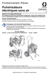
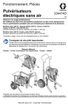
Operation, Parts Electric Airless Sprayers 334530A EN For professional use only. Not approved for use in explosive atmospheres or hazardous locations. For portable airless spraying of architectural paints and coatings. 395/490/495/595 Models: 3300 psi (228 bar, 22.8 MPa) Maximum Working Pressure See page 3 for additional model information. Important Safety Instructions Read all warnings and instructions in this manual and related manuals. Be familiar with the controls and the proper usage of the equipment. Save these instructions. Related Manuals 311861 (Contractor/FTx) 312830 (SG3) 334599 ti24941a Use only genuine Graco replacement parts. The use of non-Graco replacement parts may void warranty. Contents Contents Models . . . . . . . . . . . . . . . . . . . . . . . . . . . . . . . . . . . . . . . . . . . . . . . . . . . . . . . . . . . . . . . 3 Warnings . . . . . . . . . . . . . . . . . . . . . . . . . . . . . . . . . . . . . . . . . . . . . . . . . . . . . . . . . . . . . 4 Component Identification . . . . . . . . . . . . . . . . . . . . . . . . . . . . . . . . . . . . . . . . . . . . . . . . 8 Stand Models . . . . . . . . . . . . . . . . . . . . . . . . . . . . . . . . . . . . . . . . . . . . . . . . . . . . . . . 8 Lo-Boy Models . . . . . . . . . . . . . . . . . . . . . . . . . . . . . . . . . . . . . . . . . . . . . . . . . . . . . . 9 Hi-Boy Models . . . . . . . . . . . . . . . . . . . . . . . . . . . . . . . . . . . . . . . . . . . . . . . . . . . . . 10 Grounding . . . . . . . . . . . . . . . . . . . . . . . . . . . . . . . . . . . . . . . . . . . . . . . . . . . . . . . . . . . 12 Power Requirements . . . . . . . . . . . . . . . . . . . . . . . . . . . . . . . . . . . . . . . . . . . . . . . . 12 Extension Cords . . . . . . . . . . . . . . . . . . . . . . . . . . . . . . . . . . . . . . . . . . . . . . . . . . . 12 Pails . . . . . . . . . . . . . . . . . . . . . . . . . . . . . . . . . . . . . . . . . . . . . . . . . . . . . . . . . . . . . 12 Pressure Relief Procedure . . . . . . . . . . . . . . . . . . . . . . . . . . . . . . . . . . . . . . . . . . . . . . 13 Setup . . . . . . . . . . . . . . . . . . . . . . . . . . . . . . . . . . . . . . . . . . . . . . . . . . . . . . . . . . . . . . . 15 Startup . . . . . . . . . . . . . . . . . . . . . . . . . . . . . . . . . . . . . . . . . . . . . . . . . . . . . . . . . . . . . . 19 Operation . . . . . . . . . . . . . . . . . . . . . . . . . . . . . . . . . . . . . . . . . . . . . . . . . . . . . . . . . . . . 21 Spray Tip Installation . . . . . . . . . . . . . . . . . . . . . . . . . . . . . . . . . . . . . . . . . . . . . . . . 21 Spray . . . . . . . . . . . . . . . . . . . . . . . . . . . . . . . . . . . . . . . . . . . . . . . . . . . . . . . . . . . . 21 Clear Tip Clog . . . . . . . . . . . . . . . . . . . . . . . . . . . . . . . . . . . . . . . . . . . . . . . . . . . . . 22 Digital Display . . . . . . . . . . . . . . . . . . . . . . . . . . . . . . . . . . . . . . . . . . . . . . . . . . . . . 23 Cleanup . . . . . . . . . . . . . . . . . . . . . . . . . . . . . . . . . . . . . . . . . . . . . . . . . . . . . . . . . . 25 Maintenance . . . . . . . . . . . . . . . . . . . . . . . . . . . . . . . . . . . . . . . . . . . . . . . . . . . . . . . . . 28 Troubleshooting . . . . . . . . . . . . . . . . . . . . . . . . . . . . . . . . . . . . . . . . . . . . . . . . . . . . . . 29 Mechanical/Fluid Flow . . . . . . . . . . . . . . . . . . . . . . . . . . . . . . . . . . . . . . . . . . . . . . . 29 Electrical . . . . . . . . . . . . . . . . . . . . . . . . . . . . . . . . . . . . . . . . . . . . . . . . . . . . . . . . . 32 395/490/495 Stand Sprayers . . . . . . . . . . . . . . . . . . . . . . . . . . . . . . . . . . . . . . . . . . . . . 41 395/490/495 Stand Sprayers Parts List . . . . . . . . . . . . . . . . . . . . . . . . . . . . . . . . . . 43 395/490/495/595 Lo-Boy Sprayers . . . . . . . . . . . . . . . . . . . . . . . . . . . . . . . . . . . . . . . . 44 395/490/495/595 Lo-Boy Sprayers Parts List . . . . . . . . . . . . . . . . . . . . . . . . . . . . . 46 395/490/495/595 Hi-Boy Sprayers . . . . . . . . . . . . . . . . . . . . . . . . . . . . . . . . . . . . . . . . 47 395/490/495/595 Hi-Boy Sprayers Parts List . . . . . . . . . . . . . . . . . . . . . . . . . . . . . . 49 Accessories and Labels . . . . . . . . . . . . . . . . . . . . . . . . . . . . . . . . . . . . . . . . . . . . . . . . 50 Control Box . . . . . . . . . . . . . . . . . . . . . . . . . . . . . . . . . . . . . . . . . . . . . . . . . . . . . . . . . . 51 Control Box Parts List . . . . . . . . . . . . . . . . . . . . . . . . . . . . . . . . . . . . . . . . . . . . . . . 52 Wiring Diagrams . . . . . . . . . . . . . . . . . . . . . . . . . . . . . . . . . . . . . . . . . . . . . . . . . . . . . . 54 120V, US/Japan . . . . . . . . . . . . . . . . . . . . . . . . . . . . . . . . . . . . . . . . . . . . . . . . . . . 54 110V, UK / 230V . . . . . . . . . . . . . . . . . . . . . . . . . . . . . . . . . . . . . . . . . . . . . . . . . . . 55 Technical Specifications . . . . . . . . . . . . . . . . . . . . . . . . . . . . . . . . . . . . . . . . . . . . . . . 56 Graco Standard Warranty . . . . . . . . . . . . . . . . . . . . . . . . . . . . . . . . . . . . . . . . . . . . . . 58 Graco Information . . . . . . . . . . . . . . . . . . . . . . . . . . . . . . . . . . . . . . . . . . . . . . . . . . . . . 59 2 334530A Models Models Hi-Boy Stand VAC Lo-Boy Model Ultra MAX II 490 PC Pro Ultimate MX II 490 PC Pro Ultra MAX II 110474 495 PC Pro 120 Certified to USA Ultimate MX II CAN/CSA 495 PC Pro C22.2 No. 68 Conforms to Ultra MAX II UL 1450 595 PC Pro Ultimate MX II 595 PC Pro Ultra MAX II 490 PC Pro 120 Japan/Taiwan Ultra MAX II 495 PC Pro ST MAX II 395 PC Pro 230 ST MAX II 495 PC Pro CEE 7/7 ST MAX II 595 PC Pro 17C327 17C328 17C332 826199 826200 826201 17C333 17C334 17C335 826202 826203 826204 17C336 17C337 826205 826206 17C369 17C373 17C372 17C376 17C381 230 Europe ST MAX II 495 PC Pro Multi ST MAX II 595 PC Pro 17C374 17C377 17C382 ST MAX II 495 PC Pro ST MAX II 595 PC Pro Ultra MAX II 490 PC Pro Ultra MAX II 495 PC Pro Ultra MAX II 595 PC Pro 17C375 17C378 17C383 Ultra MAX II 490 PC 17C394 110 UK 230 Asia/ANZ 230 China 334530A 17C393 17C399 17C395 17C398 17C401 17C402 17C404 17C403 3 Warnings Warnings The following warnings are for the setup, use, grounding, maintenance, and repair of this equipment. The exclamation point symbol alerts you to a general warning and the hazard symbols refer to procedure-specific risks. When these symbols appear in the body of this manual or on warning labels, refer back to these Warnings. Product-specific hazard symbols and warnings not covered in this section may appear throughout the body of this manual where applicable. WARNING GROUNDING This product must be grounded. In the event of an electrical short circuit, grounding reduces the risk of electric shock by providing an escape wire for the electric current. This product is equipped with a cord having a grounding wire with an appropriate grounding plug. The plug must be plugged into an outlet that is properly installed and grounded in accordance with all local codes and ordinances. • Improper installation of the grounding plug is able to result in a risk of electric shock. • When repair or replacement of the cord or plug is required, do not connect the grounding wire to either flat blade terminal. • The wire with insulation having an outer surface that is green with or without yellow stripes is the grounding wire. • Check with a qualified electrician or serviceman when the grounding instructions are not completely understood, or when in doubt as to whether the product is properly grounded. • Do not modify the plug provided; if it does not fit the outlet, have the proper outlet installed by a qualified electrician. • This product is for use on a nominal 120V or 230V circuit and has a grounding plug similar to the plugs illustrated below. 120V US 230V 110V UK ti24583a • Only connect the product to an outlet having the same configuration as the plug. • Do not use an adapter with this product. Extension Cords: • Use only a 3-wire extension cord that has a grounding plug and a grounding receptacle that accepts the plug on the product. • Make sure your extension cord is not damaged. If an extension cord is necessary use 12 AWG (2.5mm2) minimum to carry the current that the product draws. • An undersized cord results in a drop in line voltage and loss of power and overheating. 4 334530A Warnings WARNING FIRE AND EXPLOSION HAZARD Flammable fumes, such as solvent and paint fumes, in work area can ignite or explode. To help prevent fire and explosion: • Do not spray flammable or combustible materials near an open flame or sources of ignition such as cigarettes, motors, and electrical equipment. • Paint or solvent flowing through the equipment is able to result in static electricity. Static electricity creates a risk of fire or explosion in the presence of paint or solvent fumes. All parts of the spray system, including the pump, hose assembly, spray gun, and objects in and around the spray area shall be properly grounded to protect against static discharge and sparks. Use Graco conductive or grounded high-pressure airless paint sprayer hoses. • Verify that all containers and collection systems are grounded to prevent static discharge. Do not use pail liners unless they are antistatic or conductive. • Connect to a grounded outlet and use grounded extensions cords. Do not use a 3-to-2 adapter. • Do not use a paint or a solvent containing halogenated hydrocarbons. • Do not spray flammable or combustible liquids in a confined area. • Keep spray area well-ventilated. Keep a good supply of fresh air moving through the area. • Sprayer generates sparks. Keep pump assembly in a well ventilated area at least 20 feet (6.1 m) from the spray area when spraying, flushing, cleaning, or servicing. Do not spray pump assembly. • Do not smoke in the spray area or spray where sparks or flame is present. • Do not operate light switches, engines, or similar spark producing products in the spray area. • Keep area clean and free of paint or solvent containers, rags, and other flammable materials. • Know the contents of the paints and solvents being sprayed. Read all Material Safety Data Sheets (MSDS) and container labels provided with the paints and solvents. Follow the paint and solvents manufacturer’s safety instructions. • Fire extinguisher equipment shall be present and working. SKIN INJECTION HAZARD High-pressure spray is able to inject toxins into the body and cause serious bodily injury. In the event that injection occurs, get immediate surgical treatment. • Do not aim the gun at, or spray any person or animal. • Keep hands and other body parts away from the discharge. For example, do not try to stop leaks with any part of the body. • Always use the nozzle tip guard. Do not spray without nozzle tip guard in place. • Use Graco nozzle tips. • Use caution when cleaning and changing nozzle tips. In the case where the nozzle tip clogs while spraying, follow the Pressure Relief Procedure for turning off the unit and relieving the pressure before removing the nozzle tip to clean. • Equipment maintains pressure after power is shut off. Do not leave the equipment energized or under pressure while unattended. Follow the Pressure Relief Procedure when the equipment is unattended or not in use, and before servicing, cleaning, or removing parts. • Check hoses and parts for signs of damage. Replace any damaged hoses or parts. • This system is capable of producing 3300 psi. Use Graco replacement parts or accessories that are rated a minimum of 3300 psi. • Always engage the trigger lock when not spraying. Verify the trigger lock is functioning properly. • Verify that all connections are secure before operating the unit. • Know how to stop the unit and bleed pressure quickly. Be thoroughly familiar with the controls. 334530A 5 Warnings WARNING EQUIPMENT MISUSE HAZARD Misuse can cause death or serious injury. • Always wear appropriate gloves, eye protection, and a respirator or mask when painting. • Do not operate or spray near children. Keep children away from equipment at all times. • Do not overreach or stand on an unstable support. Keep effective footing and balance at all times. • Stay alert and watch what you are doing. • Do not operate the unit when fatigued or under the influence of drugs or alcohol. • Do not kink or over-bend the hose. • Do not expose the hose to temperatures or to pressures in excess of those specified by Graco. • Do not use the hose as a strength member to pull or lift the equipment. • Do not spray with a hose shorter than 25 feet. • Do not alter or modify equipment. Alterations or modifications may void agency approvals and create safety hazards. • Make sure all equipment is rated and approved for the environment in which you are using it. ELECTRIC SHOCK HAZARD This equipment must be grounded. Improper grounding, setup, or usage of the system can cause electric shock. • Turn off and disconnect power cord before servicing equipment. • Connect only to grounded electrical outlets. • Use only 3-wire extension cords. • Ensure ground prongs are intact on power and extension cords. • Do not expose to rain. Store indoors. PRESSURIZED ALUMINUM PARTS HAZARD Use of fluids that are incompatible with aluminum in pressurized equipment can cause serious chemical reaction and equipment rupture. Failure to follow this warning can result in death, serious injury, or property damage. • Do not use 1,1,1-trichloroethane, methylene chloride, other halogenated hydrocarbon solvents or fluids containing such solvents. • Do not use chlorine bleach. • Many other fluids may contain chemicals that can react with aluminum. Contact your material supplier for compatibility. MOVING PARTS HAZARD Moving parts can pinch, cut, or amputate fingers and other body parts. • Keep clear of moving parts. • Do not operate equipment with protective guards or covers removed. • Pressurized equipment can start without warning. Before checking, moving, or servicing equipment, follow the Pressure Relief Procedure and disconnect all power sources. TOXIC FLUID OR FUMES HAZARD Toxic fluids or fumes can cause serious injury or death if splashed in the eyes or on skin, inhaled, or swallowed. • Read MSDSs to know the specific hazards of the fluids you are using. • Store hazardous fluid in approved containers, and dispose of it according to applicable guidelines. 6 334530A Warnings WARNING PERSONAL PROTECTIVE EQUIPMENT Wear appropriate protective equipment when in the work area to help prevent serious injury, including eye injury, hearing loss, inhalation of toxic fumes, and burns. This protective equipment includes but is not limited to: • Protective eyewear, and hearing protection. • Respirators, protective clothing, and gloves as recommended by the fluid and solvent manufacturer. CALIFORNIA PROPOSITION 65 This product contains a chemical known to the State of California to cause cancer, birth defects or other reproductive harm. Wash hands after handling. 334530A 7 Component Identification Component Identification Stand Models M B U A K V W S D R P N G J F F L H ti24942a A B D F G H J K L 8 ON/OFF Switch Pressure Control Prime Valve Tip Guard Spray Tip Gun Airless Hose Power Cord Trigger Lock M N P R S U V W Drain Tube Fluid Intake Pump Fluid Outlet Power Cord Wrap Filter Finger Guard / TSL Fill Point Display Model/Serial Tag (Not shown, located on bottom of unit.) 334530A Component Identification Lo-Boy Models B M A K V W U D R P N G J F F L H ti24943a A B D F G H J K L ON/OFF Switch Pressure Control Prime Valve Tip Guard Spray Tip Gun Airless Hose Power Cord Trigger Lock 334530A M N P R U V W Drain Tube Fluid Intake Pump Fluid Outlet Filter Finger Guard / TSL Fill Point Display Model/Serial Tag (Not shown, located on bottom of unit.) 9 Component Identification Hi-Boy Models S A B T U K V W P D R M N G J F F L H ti24944a 10 334530A Component Identification Hi-Boy Models A B D F G H J K L M N ON/OFF Switch Pressure Control Prime Valve Tip Guard Spray Tip Gun Airless Hose Power Cord Trigger Lock Drain Tube Fluid Intake 334530A P R S T U V W Pump Fluid Outlet Hanger Filter Finger Guard / TSL Fill Point Pail Hook Display Model/Serial Tag (Not shown, located on bottom of unit.) 11 Grounding Grounding The equipment must be grounded to reduce the risk of static sparking and electric shock. An electric or static spark can cause fumes to ignite or explode. An improper ground can cause electric shock. A good ground provides an escape wire for the electric current. This sprayer includes a ground wire with an appropriate ground contact. The plug must be plugged into an outlet that is properly installed and grounded in accordance with all local codes and ordinances. Always ground a metal pail: connect a ground wire to the pail. Clamp one end to the pail and the other end to a true earth ground such as a water pipe. Do not modify the plug provided; if it does not fit the outlet, have the proper outlet installed by a qualified electrician. Power Requirements • 100-120V units require 100-120 VAC, 50/60 Hz, 15A, 1 phase. • 230V units require 230 VAC, 50/60 HZ, 7A, 1 phase. ti24584a To maintain ground continuity when sprayer is flushed or pressure is relieved: hold metal part of spray gun firmly to the side of a grounded metal pail then trigger the gun. Extension Cords Use an extension cord with an undamaged ground contact. If an extension cord is necessary, use a 3-wire, 12 AWG (2.5 mm2) minimum. NOTE: Smaller gauge or longer extension cords may reduce sprayer performance. Pails Solvent and oil-based fluids: follow local code. Use only conductive metal pails, placed on a grounded surface such as concrete. Do not place pail on a non-conductive surface such as paper or cardboard which interrupts grounding continuity. 12 ti24585a 334530A Pressure Relief Procedure Pressure Relief Procedure Follow the Pressure Relief Procedure whenever you see this symbol. 3. Remove tip guard. This equipment stays pressurized until pressure is manually relieved. To help prevent serious injury from pressurized fluid, such as skin injection, splashed fluid and moving parts, follow the Pressure Relief Procedure whenever sprayer is stopped and before sprayer is cleaned or checked, and before equipment is serviced. 1. Turn ON/OFF switch to OFF position. Wait 7 seconds for power to dissipate. ti24592a 4. Turn pressure control to lowest setting. Disengage trigger lock. ti24586a 2. Engage trigger lock. ti24953a ti24931a 334530A 13 Pressure Relief Procedure 5. Hold a metal part of the gun firmly to a grounded metal pail. Trigger the gun to relieve pressure. 8. If you suspect the spray tip or hose is clogged or that pressure has not been fully relieved: a. VERY SLOWLY loosen tip guard retaining nut or hose end coupling to relieve pressure gradually. b. c. Loosen nut or coupling completely. Clear hose or tip obstruction. Trigger Lock Always engage the trigger lock when sprayer is stopped to prevent the gun from being triggered accidentally by hand or if dropped or bumped. ti24585a 6. Engage trigger lock. 7. Put drain tube in pail. Turn prime valve down. Leave prime valve in down (drain) position until you are ready to spray again. ti24612a ti24607a 14 334530A Setup Setup 2. Connect other end of hose to gun. When unpacking sprayer for the first time or after long term storage perform setup procedure. When first setup is performed remove shipping plug from fluid outlet. 1. Connect Graco airless hose to fluid outlet. Use wrenches to tighten securely. ti24633a 3. Use wrenches to tighten securely. 4. Engage trigger lock. ti24931a ti24616a 334530A 15 Setup 5. Remove tip guard. ti24638a 7. ti24592a 6. When unpacking sprayer for the first time remove packaging materials from inlet strainer. After long term storage check inlet strainer for clogs and debris. Fill throat packing nut with TSL to prevent premature packing wear. Do this daily or each time you spray. a. Place the TSL bottle nozzle into the top center opening in the grill at the front of the sprayer. b. Squeeze bottle to dispense enough TSL to fill the space between the pump rod and packing nut seal. ti24639a 16 334530A Setup 8. Make certain ON/OFF switch is OFF. 11. Place fluid intake with drain tube in grounded metal pail partially filled with flushing fluid. See Grounding, page 12. NOTE: New sprayers are shipped with storage fluid that must be flushed out with mineral spirits prior to using the sprayer. ti24586a 9. Plug power supply cord into a properly grounded electrical outlet. Check flushing fluid for compatibility with material that is to be sprayed. A secondary flush with a compatible fluid may be necessary. Water for latex paint or mineral spirits for oil-based paint. ti24651a 10. Turn prime valve down. ti24640a 12. Turn pressure control to OFF. 13. Turn ON/OFF switch to ON position. 14. Turn prime valve horizontal. Disengage trigger lock. 15. Turn pressure control to Prime/Slow. 16. Hold a metal part of the gun firmly to a grounded metal pail. Trigger gun and flush for one minute. 17. Turn ON/OFF switch to OFF position. 18. Engage trigger lock. 19. After flushing storage fluid out of the sprayer empty pail. Replace fluid intake with drain tube in grounded metal pail partially filled with flushing fluid. Use water to flush water-based paint or mineral spirits to flush oil-based paint. 20. Turn ON/OFF switch to ON position. ti24608a 334530A 21. Turn prime valve horizontal. Disengage trigger lock. 17 Setup 22. Hold a metal part of the gun firmly to a grounded metal pail. Trigger gun and flush until clean. 18 23. Turn ON/OFF switch to OFF position. 24. Engage trigger lock. 25. Sprayer is now ready to startup and spray. 334530A Startup Startup 1. Perform Pressure Relief Procedure, page 13. 2. Turn pressure control to lowest pressure. ti24953a 3. Turn ON/OFF switch to ON position. ti24646a 7. Hold gun against grounded metal waste pail. Trigger gun until paint appears. ti24644a 4. Place fluid intake in paint pail. Place drain tube in waste pail. 5. Turn pressure control to Fast Flush to start motor. Allow paint to circulate through drain tube for 15 seconds. 15 s ti24954a 6. Turn prime valve horizontal. Disengage trigger lock. 334530A 1m ti24647a 19 Startup 8. Move gun to paint pail and trigger for 20 seconds. Release trigger and allow sprayer to build pressure. Engage trigger lock. 10. Screw tip assembly onto gun and tighten. See Spray Tip Installation, page 21. For gun assembly instructions, see separate gun manual. 20 s ti24649a ti24652a High-pressure spray is able to inject toxins into the body and cause serious bodily injury. Do not stop leaks with hand or rag. 9. 20 Inspect for leaks. If leaks occur, perform Pressure Relief Procedure, page 13, then tighten all fittings and repeat Startup procedure. If there are no leaks continue with the next step. 334530A Operation Operation Spray Tip Installation 3. Screw assembly onto gun. Tighten. 1. Perform Pressure Relief Procedure, page 13. 2. Use spray tip (A) to insert OneSeal™ (B) into tip guard (C). C B A ti24653a 2. Insert Spray Tip. ti24652a Spray 1. Spray test pattern. Adjust pressure to eliminate heavy edges. ti24664a ti24669a 334530A 21 Operation 2. Use smaller tip size if pressure adjustment cannot eliminate heavy edges. 3. Hold gun perpendicular, 10-12 in. (25-30 cm) from surface. Spray back and forth; overlap by 50%. ti24674a 2. ti24673a 4. Engage trigger lock. Return Spray Tip to original position. Disengage trigger lock and continue spraying. Trigger gun after moving. Release trigger before stopping. For additional spraying information, see separate gun manual. Clear Tip Clog 1. Release trigger. Engage trigger lock. Rotate Spray Tip. Disengage trigger lock. Trigger gun at waste area to clear clog. ti24676a 22 334530A Operation Digital Display 4. Press and hold display button to change pressure units (psi, bar, or MPa). Most models are equipped with a digital display. This section explains how to use this feature. Pressure Display 1. Perform Pressure Relief Procedure, page 13. 2. Plug sprayer into grounded outlet. Turn ON/OFF switch to ON position. ti2888a Stored Data Display ti24651a 1. Turn ON/OFF switch to OFF position. ti24644a ti24586a 3. The pressure is displayed. Dashes indicate pressure is less than 200 psi (14 bar, 1.4 MPa). ti2786a 334530A 23 Operation 2. To enter Stored Data Mode, press and hold display button and turn ON/OFF switch to ON position. 5. Press display button again to display Data Point 3. This will be the last error code. 6. To erase last error code, press and hold display button. 7. Press display button again to display Data Point 4. The software revision is displayed. 8. Press display button again to return to Data Point 1. 9. Turn ON/OFF switch to OFF position to exit Stored Data. ti2824a ti24644a 3. 4. Sprayer model number is displayed followed by Data Point 1 which is the unit power on time in hours. Press display button again to display Data Point 2. Motor run time in hours is displayed. ti24586a 24 334530A Operation Cleanup 1. Perform Pressure Relief Procedure, page 13. 2. Remove tip guard and Spray Tip. For additional information, see separate gun manual. ti24709a 4. Place fluid intake in flushing fluid. Use water for water base paint and mineral spirits for oil-based paint. Place drain tube in waste pail. ti24592a Fast Flush Drain Tube 3. Remove fluid intake and drain tube from paint, wipe excess paint off outside. ti24710a 334530A 25 Operation 5. To flush drain tube and pump turn prime valve down. 8. Hold gun against waste pail. Disengage trigger lock. Trigger gun and turn pressure control to Fast Flush operate until the pump runs steady and flushing fluid appears. ti24713a 6. Turn pressure control to Fast Flush operate until the pump runs steady and flushing fluid appears in the waste pail. Fast Flush Hose and Gun 7. ti24991a 9. Stop triggering gun. 10. Raise fluid intake above flushing fluid. To flush airless hose and spray gun, turn prime valve horizontal. ti24714a 26 334530A Operation 11. With prime valve horizontal. Trigger gun into flushing pail to purge fluid from hose. 12. Engage trigger lock. ti24718a 20 s 15. If flushing with water, flush again with mineral spirits or Pump Armor to leave a protective coating to prevent freezing or corrosion. ti24649a 13. Turn pressure control knob to OFF and turn ON/OFF switch to OFF position. Disconnect power to sprayer. ti24719a 16. Wipe sprayer, hose and gun with a rag soaked in water or mineral spirits. ti24992a 14. Remove filter from gun and sprayer if installed. Clean and inspect. Install filter. See separate gun manual. ti24720a 334530A 27 Maintenance Maintenance Routine maintenance is important to ensure proper operation of your sprayer. Maintenance includes performing routine actions which keep your sprayer in operation and prevents trouble in the future. Activity Interval Inspect/clean sprayer filter, fluid inlet strainer, and gun filter. Daily or each time you spray Inspect motor shield vents for blockage. Fill TSL by adding through TSL fill point. Inspect motor brushes for wear. Brushes must be 1/2 in. (13mm) minimum length. NOTE: Brushes do not wear at the same rate on both sides of motor. Check both brushes. Check sprayer stall. Daily or each time you spray Daily or each time you spray Every 1000 gallons (3785 liters) Every 1000 gallons (3785 liters) With sprayer gun NOT triggered, sprayer motor should stall and not restart until gun is triggered again. If sprayer starts again with gun NOT triggered, inspect pump for internal/external leaks and check prime valve for leaks. Throat packing adjustment As necessary based on usage When pump packing begins to leak after extended use, tighten packing nut down until leakage stops or lessens. This allows approximately 100 gallons of additional operation before a repacking is required. Packing nut can be tightened without 0-ring removal. 28 334530A Troubleshooting Troubleshooting Mechanical/Fluid Flow 1. Follow Pressure Relief Procedure, page 13, before checking or repairing. Problem 2. Check all possible problems and causes before disassembling the unit. What to Check If check is OK, go to next check What to Do When check is not OK, refer to this column For units with display: E=0X is displayed. For units with no display: Control board status light is blinking or the light is off and there is power to the sprayer. Fault condition exists. Determine fault correction from Electrical, page 32. Pump output is low Spray tip worn. Follow Pressure Relief Procedure, page 13, then replace tip. See separate gun or tip manual. Spray tip clogged. Relieve pressure. Check and clean spray tip. Paint supply. Refill and reprime pump. Intake strainer clogged. Remove and clean, then reinstall. Intake valve ball and piston ball are not seating properly. Remove intake valve and clean. Check balls and seats for nicks; replace if necessary. See pump manual. Strain paint before using to remove particles that could clog pump. Fluid filter or tip filter is clogged or dirty. Clean filter. Prime valve leaking. Follow Pressure Relief Procedure, page 13, then repair prime valve. Verify pump does not continue to stroke when gun trigger is released. (Prime valve not leaking.) Service pump. See pump manual. Leaking around throat packing nut Replace packings. See pump manual. which may indicate worn or damaged Also check piston valve seat for packings. hardened paint or nicks and replace if necessary. Tighten packing nut/wet-cup. 334530A 29 Troubleshooting Problem Pump output is low What to Check If check is OK, go to next check What to Do When check is not OK, refer to this column Pump rod damage. Repair pump. See pump manual. Low stall pressure. Turn pressure knob fully clockwise. Make sure pressure control knob is properly installed to allow full clockwise position. If problem persists, replace pressure transducer. Piston packings are worn or damaged. Replace packings. See pump manual. O-ring in pump is worn or damaged. Replace o-ring. See pump manual. Intake valve ball is packed with material. Clean intake valve. See pump manual. Large pressure drop in hose with heavy materials. Reduce overall length of hose. Check extension cord for correct size. See Extension Cords, page 12. Loose motor brushes and terminals. Tighten terminal screws. Replace brushes if leads are damaged. Worn motor brushes. (Brushes must be 1/2 in. [13mm] minimum length.) Replace brushes. Broken and misaligned motor brush Replace spring if broken. Realign springs. Rolled portion of spring must spring with brush. rest squarely on top of brush. Motor runs but pump does not stroke Excessive paint leakage into throat packing nut 30 Motor brushes are binding in brush holders. Clean brush holders, remove carbon dust with a small cleaning brush. Align brush lead with slot in brush holder to assure free vertical brush movement. Connecting rod assembly damaged. See pump manual. Replace connecting rod assembly. See pump manual. Gears or drive housing damaged. Inspect drive housing assembly and gears for damage and replace if necessary. Throat packing nut is loose. Remove throat packing nut spacer. Tighten throat packing nut just enough to stop leakage. Throat packings are worn or damaged. Replace packings. See pump manual. Displacement rod is worn or damaged. Replace rod. See pump manual. 334530A Troubleshooting Problem Fluid is spitting from gun Pump is difficult to prime Sprayer operates for 5 to 10 minutes then stops 334530A What to Check If check is OK, go to next check What to Do When check is not OK, refer to this column Air in pump or hose. Check and tighten all fluid connections. Cycle pump as slowly as possible during priming. Spray tip is partially clogged. Clear tip. See Clear Tip Clog, page 22. Fluid supply is low or empty. Refill fluid supply. Prime pump. See pump manual. Check fluid supply often to prevent running pump dry. Air in pump or hose. Check and tighten all fluid connections. Cycle pump as slowly as possible during priming. Intake valve is leaking. Clean intake valve. Be sure ball seat is not nicked or worn and that ball seats well. Reassemble valve. Pump packings are worn. Replace pump packings. See pump manual. Paint is too thick. Thin the paint according to supplier recommendations. Pump packing nut too tight. When pump packing nut is too tight the packings on the pump rod restrict pump action and overloads the motor. Loosen pump packing nut. Check for leaks around throat. If necessary, replace pump packings. See Pump manual. 31 Troubleshooting Electrical 4. Symptom: Sprayer does not run, stops running, or will not shut off. Perform Pressure Relief Procedure, page 13. 1. Plug sprayer into correct voltage, grounded outlet. 2. Turn the ON/OFF switch OFF wait 30 seconds and then turn power back ON again (this ensures sprayer is in normal run mode). 3. Turn pressure control knob clockwise 1/2 turn. View digital display or remove control box cover to view control board status light. To determine which code (or any other code besides voltage supply) refer to the control board status light. Turn the ON/OFF switch OFF, remove the control cover then turn power back ON. Observe the status light. Blinking LED total count equals the error code (for example: two blinks equals CODE 02).Press display button to restart code messages. Keep clear of electrical and moving parts during troubleshooting procedures. To avoid electrical shock hazards when covers are removed for troubleshooting, wait 7 seconds after disconnecting power cord for stored electricity to dissipate. Error Code Messages CODE MESSAGE ACTION 02 HIGH PRESSURE DETECTED - RELIEVE PRESSURE Check for clogs. Use only Graco spray hoses, use a minimum of 50ft/15m. 03 PRESSURE TRANSDUCER NOT DETECTED Check transducer connection. 05 MOTOR NOT SPINNING Check for mechanical failure and check motor connections. Material may be too thick, thin material. 06 MOTOR OVERHEATED Turn sprayer OFF. Check motor connections. Check shroud vents for blockage. Sprayer may take up to an hour to cool. 32 334530A Troubleshooting Problem What to Check How to check Sprayer does not run at all See flow chart, page 38. AND Display is blank OR Control board status light never lights Sprayer does not shut off AND Displays Code 02 message OR Control board status light blinks 2 times repeatedly Control board. Replace control board. Sprayer does not run at all AND Displays Code 02 message OR Control board status light blinks 2 times repeatedly Check transducer or transducer connections Make sure there is no pressure in the system (see Pressure Relief Procedure, page 13). Check fluid path for clogs, such as clogged filter. Use airless paint spray hose with no metal braid. A small hose or metal braid hose may result in high-pressure spikes. Turn ON/OFF switch OFF and disconnect power to sprayer. Check transducer and connections to control board. Disconnect transducer from control board socket. Check that transducer and control board contacts are clean and secure. Reconnect transducer to control board socket. Connect power, turn ON/OFF switch ON and control knob 1/2 turn clockwise. If sprayer does not run properly, turn ON/OFF switch OFF and go to next step. Install new transducer. Connect power, turn ON/OFF switch ON and control knob 1/2 turn clockwise. Replace control board if sprayer does not run properly. 334530A 33 Troubleshooting Problem What to Check How to check Sprayer does not run at all AND Displays Code 03 message OR Control board status light blinks 3 times repeatedly Check transducer or transducer connections (control board is not detecting a pressure signal). Turn ON/OFF switch OFF and disconnect power to sprayer. Check transducer and connections to control board. Disconnect transducer from control board socket. Check to see if transducer and control board contacts are clean and secure. Reconnect transducer to control board socket. Connect power, turn ON/OFF switch ON and control knob to 1/2 turn clockwise. If sprayer does not run, turn ON/OFF switch OFF and go to next step. Connect a confirmed working transducer to control board socket. Turn ON/OFF switch ON and control knob to 1/2 turn clockwise. If sprayer runs, install new transducer. Replace control board if sprayer does not run. Check transducer resistance with an ohmmeter (less than 9k ohm between red and black wires and 3-6k ohm between green and yellow wires). Sprayer does not run at all AND Displays Code 05 message OR Control board status light blinks 5 times repeatedly Control is commanding motor to run but motor shaft does not rotate. Possibly locked rotor condition, an open connection exists between motor and control, there is a problem with motor or control board, or motor amp draw is excessive. 1.Remove pump and try to run sprayer. If motor runs, check for locked or frozen pump or drive train. If sprayer does not run, continue to step 2. 2.Turn ON/OFF switch OFF and disconnect power to sprayer. 3.Disconnect motor connector(s) from control board socket(s). Check that motor connector and control board contacts are clean and secure. If contacts are clean and secure, continue to step 4. 4.Set sprayer to OFF and spin motor fan 1/2 turn. Restart sprayer. If sprayer runs replace control board. If sprayer does not run, continue to step 5. 34 334530A Troubleshooting Problem What to Check How to check 5.Perform Spin Test: Test at large 4-pin motor field connector. Disconnect fluid pump from sprayer. Test motor by placing a jumper across pins 1 & 2. Rotate motor fan at about 2 revolutions per second. A cogging resistance to motion should be felt at the fan. The motor should be replaced if no resistance is felt. Repeat for pin combinations 1 & 3 and 2 & 3. Pin 4 (the green wire) is not used in this test. If all spin test is positive, continue to step 6. GRN BLU R BLK STEP 1: GRN BLU R BLK STEP 2: GRN BLU R BLK STEP 3: 334530A 35 Troubleshooting Problem What to Check How to check 6.Perform Field Short Test: Test at large 4-pin motor field connector. There should not be continuity from pin 4, the ground wire, and any of the remaining 3 pins. If motor field connector tests fail, replace motor. 7.Check Motor Thermal Switch: Unplug thermal wires. Set meter to ohms. Meter should read 100k ohms. 1-3 ohms - 8.Reconnect motor connector(s) to control board socket(s). Connect power, turn ON/OFF switch ON and control knob to 1/2 turn clockwise. If motor does not run, replace control board. 36 334530A Troubleshooting Problem What to Check How to check Sprayer does not run at all AND Displays Code 06 message OR Control board status light blinks 6 times repeatedly Motor is hot or there is a fault in the motor thermal device. Allow sprayer to cool. If sprayer runs when cool, correct cause of overheating. Keep sprayer in cooler location with good ventilation. Make sure motor air intake is not blocked. If sprayer still does not run, replace motor. NOTE: Motor must be cooled down for the test. 1. Check thermal device connector (yellow wires) at control board. 2. Disconnect thermal device connector from control board socket. Make sure contacts are clean and secure. Measure resistance of the thermal device. If reading is not correct, replace motor. Check Motor Thermal Switch: Unplug thermal wires. Set meter to ohms. Meter should read 100k ohms. 3. Reconnect thermal device connector to control board socket. Connect power, turn sprayer ON and control knob 1/2 turn clockwise. If sprayer does not run, replace control board. Basic electrical problems Motor leads are securely fastened and properly mated Replace loose terminals; crimp to leads. Be sure terminal are firmly connected. Clean circuit board terminals. Securely reconnect leads. For loose motor brush lead connections and terminals. Tighten terminal screws. Replace brushes if leads are damaged. Brushes must be 1/2 in. [13mm] minimum length. NOTE: Brushes do not wear at the same rate on both sides of motor. Check both brushes. Replace brushes. Broken or misaligned motor brush Replace spring if broken. Realign springs. Rolled portion of spring must spring with brush. rest squarely on top of brush. Motor brushes may be binding in brush holders. Clean brush holders. Remove carbon with small cleaning brush. Align brush leads with slot in brush holder to assure free vertical brush movement. Motor armature commutator for burn Remove motor and have motor shop spots, gouges or extreme roughness. resurface commutator if possible. 334530A 37 Troubleshooting Sprayer Will Not Run (See following page for steps) Sprayer Will Not Run (see following pages for steps) Remove Control box cover. Turn sprayer ON. Observe control board status light on control board (see page 27). See Step 1. Do you have over 100 VAC (220 VAC for 230v units)? No Light Once Normal Operation YES Control board Light on continuously Commanding motor to run Flashing See Code section for further troubleshooting See Step 3. Is there Continuity through the thermal switch wires? NO NO See Step 2. Do you have over 100 VAC (220 VAC for 230v units)? YES NO Replace the On/Off switch. Repair or replace power cord. If motor is hot, let cool and retest. If Step 3 still shows no continuity, replace motor. The motor has a defective thermal device. YES See Step 4. Does the motor run? NO Connect a test transducer to the board. Does the motor run? YES YES NO Replace the potentiometer. Replace the transducer Replace the control board ti24726a 38 334530A Troubleshooting Step 1: Step 2: Plug Power cord in and turn switch ON. Connect probes to ontrol board. Turn meter to AC Volts. Plug Power cord in and turn switch ON. Connect probes to control board. Turn meter to AC Volts 110-120 AC 110-120 AC V V - - On/Off Switch Blue Brown Power Cord Green Power Cord Green Black Blue Step 3: Step 4: Check motor thermal switch. Unplug yellow wires. Meter should read 100 ohms. NOTE: Motor should be cool during reading. Disconnect potentiometer. Plug power cord in and turn switch ON. Control Board To Potentiometer 100 ohms Yellow Thermistor Wires to motor - + ti24084a 334530A 39 Troubleshooting Sprayer Will Not Shut Off 1. Perform Pressure Relief Procedure, page 13. Leave prime valve open (down) and turn ON/OFF switch OFF. 2. Remove control box cover so the control board status light can be viewed if available. Troubleshooting Procedure Troubleshooting Procedure Plumb pressure gauge into paint hose, plug sprayer in, and turn power switch ON. Does sprayer reach or exceed its maximum pressure? NO Mechanical problem: See the proper fluid pump manual for the sprayer for further troubleshooting procedures. NO Replace the control board. NO Replace the control board. YES Is the control board status light on? YES Unplug the transducer from control board. Does motor stop running? YES Bad transducer. Replace and test with a new one. ti24731a 40 334530A 395/490/495 Stand Sprayers 395/490/495 Stand Sprayers Ref. Torque 1 140-160 in-lb (15.8 - 18.1 N•m) 2 30-35 in-lb (3.4 - 4.0 N•m) 63 2 23 2 12 53 65 54 54a 54b 68 71 59 47 1 47 67 1 See page 51. ti24994a 334530A 41 395/490/495 Stand Sprayers Ref. Torque 1 140-160 in-lb (15.8 - 18.1 N•m) 2 30-35 in-lb (3.4 - 4.0 N•m) 3 Hammer tight 4 25-30 ft-lb (33.9 - 40.7 N•m) 66 69 40 44 25 42 47 1 22 52 132 43 45 70 12 2 3 41 13 62 14 60 55 4 39 57 ti24993a 42 334530A 395/490/495 Stand Sprayers 395/490/495 Stand Sprayers Parts List Ref. Part 12 117501 13 14 22 23 115099 117559 17C541 15G449 25 33 180131 206994 34 See page 50 39 241920 40 41 249194 42 17C487 17C488 17C489 24W817 43 44 24W640 24X020 45 24W830 46 See page 50 117493 47 52 53 54* Description SCREW, mach, hex washer hd WASHER, hose O-ring COVER, front, painted SHIELD, motor, painted BEARING, thrust FLUID, TSL (not shown) CARD, medical alert (not shown) DEFLECTOR, threaded GEAR, reducer PUMP, displacement, PC North America Europe Asia/ANZ/Japan HOUSING, drive, PC, includes 12, 47, 70 ROD, connecting, PC KIT, repair, crankshaft, includes 25 KIT, hose, cpld, PC, includes 132 HOSE, cpld, 1/4 in. x 50 ft (not shown) SCREW, mach, hex washer hd LABEL, front, upper/lower LABEL, side See page 50 See page 50 24S022 MOTOR, kit includes 54a, 54b 334530A Qty. 4 Ref. Part Description Qty. 1 1 9 FAN, motor SCREW, mach, torx, painted 55 246381 HOSE, drain, stand, includes 39,62 57 246385 STRAINER, 7/8-14 unf 59 15E823 FRAME, standmount 60 246386 KIT, hose suction, includes 13, 14, 57, 62 61 See page GUN, spray (not 50 shown) 62 276888 CLIP, drain line 63 See page LABEL, danger 50 65 See page LABEL, warning 50 66 116139 GRIP, handle 67 15G857 CAP, leg 68 287903 CUP, suction/drain 69 287072 HANDLE, sprayer, includes 47, 66 70 17C483 COVER, pump rod 71 122667 SCREW, drill, hex washer head 108 115523 GAUGE, pressure, fluid, not shown (on select models) 132 16H137 PACKING, O-ring 139 127914 SCREW, mach, slot, hex 1 * For motor brush kit order 287735 1 Replacement Danger and Warning labels, tags, and cards are available at no cost. 1 2 1 1 1 1 1 1 1 1 1 1 1 1 1 1 54a 15D088 54b 115477 1 1 1 1 1 1 1 1 4 1 1 1 1 1 1 3 43 395/490/495/595 Lo-Boy Sprayers 395/490/495/595 Lo-Boy Sprayers Ref. 63 2 12 Torque 1 140-160 in-lb (15.8 - 18.1 N•m) 2 30-35 in-lb (3.4 - 4.0 N•m) 23 53 65 54a 54 54b See page 51. 82 83 150 59 47 68 44 66 74 1 69 71 ti24996a 334530A 395/490/495/595 Lo-Boy Sprayers Ref. Torque 1 140-160 in-lb (15.8 - 18.1 N•m) 2 30-35 in-lb (3.4 - 4.0 N•m) 3 Hammer tight 4 25-30 ft-lb (33.9 - 40.7 N•m) 117 42 40 44 47 1 22 25 52 60 55 43 12 70 62 2 3 45 132 41 13 4 14 39 57 60 ti24995a 334530A 45 395/490/495/595 Lo-Boy Sprayers 395/490/495/595 Lo-Boy Sprayers Parts List Ref. Part 12 117501 13 14 22 23 115099 117559 17C541 15G449 25 33 180131 206994 34 See page 50 39 241920 40 41 42 43 44 45 46 47 52 53 249194 17C487 17C489 24W817 24W640 24X020 24X021 24W830 See page 50 117493 See page 50 See page 50 54* 24S022 46 Description Qty. SCREW, mach, hex washer hd WASHER, hose O-ring COVER, front, painted SHIELD, motor, painted BEARING, thrust FLUID, TSL (not shown) CARD, medical alert (not shown) DEFLECTOR, threaded GEAR, reducer PUMP, displacement, PC North America Asia, ANZ, Japan HOUSING, drive, PC, includes 12, 47, 70 ROD, connecting, PC KIT, repair, crankshaft, includes 25 Models 395/490/495 Model 595 KIT, hose, cpld, PC, includes 132 HOSE, cpld, 1/4 in. x 50 ft (not shown) SCREW, mach, hex washer hd LABEL, front, upper/lower LABEL, side 4 MOTOR, includes 54a, 54b Models 395/490/495 1 1 2 1 1 1 1 1 1 1 1 1 1 1 1 1 8 1 1 Ref. Part Description 287807 54a 15D088 54b 115477 Qty. Model 595 FAN, motor SCREW, mach, torx, painted 55 246381 HOSE, drain, stand, includes 39,62 57 246385 STRAINER, 7/8-14 unf 59 246250 FRAME, cart, lo 60 246386 KIT, hose suction, includes 13, 14, 57, 62, 61 See page GUN, spray (not 50 shown) 62 276888 CLIP, drain line 63 See page LABEL, danger 50 65 See page LABEL, warning 50 66 15B999 CLIP, retaining 68 104811 CAP, hub 69 287488 HANDLE, assembly, lo cart 70 17C483 COVER, pump, rod 71 107310 PLUG, tubing 74 195766 WHEEL, semi pneumatic 82 122667 SCREW, drill, hex washer head 83 15B870 CUP, suction/drain 117 15G447 PLUG, shield painted 132 16H137 PACKING, O-ring 139 127914 SCREW, mach, slot, hex 150 109032 SCREW, pan hd 1 1 1 1 1 1 1 1 1 2 2 1 1 2 2 2 1 1 1 3 4 Replacement Danger and Warning labels, tags, and cards are available at no cost. * For motor brush kit order 287735 334530A 395/490/495/595 Hi-Boy Sprayers 395/490/495/595 Hi-Boy Sprayers Ref. 2 12 74 Torque 1 140-160 in-lb (15.8 - 18.1 N•m) 2 30-35 in-lb (3.4 - 4.0 N•m) 3 23-27 in-lb (2.6 - 3.1 N•m) 63 23 53 65 54a See page 51. 54b 54 116 59 67 3 115 114 81 47 1 83 334530A 82 75 ti24998a 47 395/490/495/595 Hi-Boy Sprayers Ref. 40 44 Torque 1 140-160 in-lb (15.8 - 18.1 N•m) 2 30-35 in-lb (3.4 - 4.0 N•m) 3 Hammer tight 4 25-30 ft-lb (33.8 - 40.6 N•m) 25 117 42 1 47 107 22 52 4 43 45 105 12 70 3 2 41 132 13 14 84 69 55 87 60 62 39 57 ti24997a 48 334530A 395/490/495/595 Hi-Boy Sprayers 395/490/495/595 Hi-Boy Sprayers Parts List Ref. Part 12 117501 13 14 22 23 25 33 115099 103413 17C541 15G449 180131 206994 34 See page 50 39 241920 40 41 42 43 44 45 46 47 52 53 249194 17C487 17C488 17C489 24W817 24W640 24X020 24X021 24W830 See page 50 117493 See page 50 See page 50 54* 24S022 287807 54a 15D088 54b 115477 55 244240 334530A Description SCREW, mach, hex washer hd WASHER, hose O-ring COVER, front, painted SHIELD, motor, painted BEARING, thrust FLUID, TSL (not shown) CARD, medical alert (not shown) DEFLECTOR, threaded GEAR, reducer PUMP, displacement, PC North America Europe Asia/ANZ/Japan HOUSING, drive, PC, includes 12, 47, 70 ROD, connecting, PC KIT, repair, crankshaft, includes 25 Models 395/490/495 Model 595 KIT, hose, cpld, PC, includes 132 HOSE, cpld, 1/4 in. x 50 ft (not shown) SCREW, mach, hex washer hd LABEL, front, upper/lower LABEL, side MOTOR, includes 54a, 54b 395/490/495 595 FAN, motor SCREW, mach, torx, painted HOSE, drain, includes 39 Qty. 4 1 1 1 1 1 1 1 1 1 1 1 1 1 Ref. 57 59 60 61 62 63 65 67 69 70 74 75 81 82 83 84 87 105 107 114 1 115 1 116 8 117 122 1 Part Description 246385 17C485 17C992 STRAINER, 7/8-14 unf FRAME, cart, hi KIT, stinger tube, includes 13,14, 57, 69, 76, 84, 87 See page GUN, spray (not shown) 50 276888 CLIP, drain line See page LABEL, danger 50 See page LABEL, warning 50 109032 SCREW, pan hd 15E813 NUT, jam 17C483 COVER, pump rod 287489 HANDLE 108691 PLUG, tubing 106062 WHEEL 15B999 CLIP, retaining 104811 CAP, hub 15B652 WASHER, suction 17C281 TUBE, suction 17C990 HANGER, pail 111040 NUT, lock, insert, nylon 15D281 HANGER, stand (on select models) 15C982 CAM, cart (on select models) 114531 SCREW, mch, hex (on select models) 15G447 PLUG, tubing 118852 SCREW, thd forming (on select models, not shown) 287184 TOOL BOX (on select models, not shown) 16H137 PACKING, O-ring 127914 SCREW, mach, slot, hex Qty. 1 1 1 1 1 1 4 1 1 1 2 2 2 2 1 1 1 2 1 2 4 1 3 1 123 1 132 139 1 1 Replacement Danger and Warning labels, tags, and cards are available at no cost. 1 * For motor brush kit order 287735 1 1 3 49 Accessories and Labels Accessories and Labels Sprayer Model 826199 826200 826201 826202 826203 826204 826205 826206 17C327 17C328 17C332 17C333 17C334 17C335 17C336 17C337 17C369 17C372 17C373 17C374 17C375 17C376 17C377 17C378 17C381 17C382 17C383 17C393 Ref. 34 Card, Medical Alert Ref. 46 Hose, 1/4 in. x 50 ft 222385 # 826079 222385 # Ref. 52 Label, Front, Upper/ Lower Ref. 53 Label, Side Ref. 61 Gun, Spray Ref. 63 Ref. 65 Label, Label, Danger Warning 17C830/ 17C831 17C832 826085 15H085 # 195793 & 826079 17C830/ 17C835 17C836 826085 15H085 # 195793 & 222385 # 826079 17C830/ 17C839 17C840 826085 15H085 # 195793 & 222385 # 240794 17C827/ 17C828 17C829 288420 15H085 # 195793 & 222385 # 240794 17C827/ 17C833 17C834 288420 15H085 # 195793 & 222385 # 240794 17C838 288420 15H085 # 195793 & 222385 # 240794 17C827/ 17C837/ 17C864/ 17C866 17C867 288438 --- 16G596 222385 # 240794 17C864/ 17C868 17C869 288438 --- 16G596 222385 # 240794 17C827/ 17C837 17C838 288438 --- 16G596 222385 # 240794 17C827/ 17C828 17C827/ 17C857 17C827/ 17C828 17C827/ 17C833 17C829 17C926 17C858 288427/ 15H087 @ 195792 @ 288436 17C829 17C926 15H087 @ 195792 @ 17C834 288427/ 288436 17C827/ 17C833 17C834 288427/ 15H087 @ 195792 @ 288436 17C827/ 17C837 17C838 288427/ 15H087 @ 195792 @ 288436 17C394 17A134 240794 17C395 17A134 240794 17C399 222385 # 240794 17C398 17C401 17A134 240794 17C402 17C403 17C404 17A134 240794 288526 – Kit, accessory, hopper 15H086 * 195792 @ 15H086 * 195792 @ # – English, Spanish, French @ – Asia/ANZ – English, Chinese, Korean – Europe & – North America * – Japan Replacement Danger and Warning labels, tags, and cards are available at no cost. 50 334530A Control Box Control Box Ref. Torque 1 140-160 in-lb (15.8 - 18.1 N•m) 2 30-35 in-lb (3.4 - 4.0 N•m) 5 20-25 in-lb (2.3 - 2.8 N•m) 6 37-43 ft-lb (50.2 - 58.3 N•m) 7 130-150 in-lb (14.7 - 16.9 N•m) 8 48-72 in-lb (5.4 - 8.1 N•m) 8 17 2 18 11 16 37 108 15 129 24 6 49 38 48 3 20 47 1 26 36 35 7 19 24 58 4 27 5 6 5 51 30 56 107 128 37 127 7 113 92 106 50 47 1 12 2 91 56 90 334530A ti24999a 51 Control Box Control Box Parts List Ref. Part 2 3 4 5 6 7 11 12 15 16 17 18 19 20 24 26 27 30 35 36 52 117828 111457 111600 277364 120405 Description PACKING, o-ring PACKING, o-ring PIN, grooved GASKET, seat, valve SCREW, mach, Phillips, pan hd SCREW, slot, hex, wash hd 115498 230V and UK models 123850 120V US/Japan models 116167 KNOB, potentiometer 117501 SCREW, mach, hex washer hd MANIFOLD, fluid 15G455 Models without pressure gauge 15T811 Models with pressure gauge FILTER, fluid 246425 30 mesh 246384 60 mesh, original 246382 100 mesh 246383 200 mesh 287902 KIT, repair, filter cap includes 18 15B071 INSERT, filter 15G562 BUSHING, control box 15B120 GROMMET, transducer 162453 NIPPLE, (1/4 npsm x 1/4 npt) 15E022 SEAT, valve 187625 HANDLE, valve, drain BOARD, filter 287911 120V, GFI, US/Japan 287912 110V, UK 287913 230V 239914 VALVE, drain includes 5, 26 224807 BASE, valve Qty. 1 1 1 1 5 1 Ref. Part Description 37 256219 38 243222 47 117493 POTENTIOMETER, adj, pressure with nut TRANSDUCER, pressure control, includes 3 SCREW, mach, hex washer hd BOX, control board includes 6, 7, 11, 19, 30, 37, 49, 58, 127, 128, 129 120V, 490/495 models, US/Japan includes 19 120V, 595 models, US/Japan includes 19 230V 110V, UK LABEL, control, w/FastFlush COVER, control Models without display DIGITAL, display includes 51, 106, 107 LABEL, control Models without display Models with display CORD, power US, 490/495 models US, 595 models Japan Multicord, Asia/ANZ Europe CEE 7/7 Multicord, Europe BOOT, toggle RETAINER, plug, adapter Multicord models CEE 7/7 models CORD SET, adapter UK Australia 48 24W893 1 6 24W894 1 49 1 24W895 24W896 17D154 50 277229 24W892 51 1 1 1 1 17C964 17C875 56 2 1 1 1 58 90 253367 253371 253378 253373 242001 253369 253370 195428 195551 1 1 91 253368 242005 Qty. 1 1 4 1 1 1 1 1 1 2 1 1 334530A Control Box Ref. Part Description Qty. 287121 Italy, Denmark, Sweden 92 244285 ADPTER, Japan 106 15G861 LABEL, smart control display 107 15G588 LABEL, digital tracking system 108 115523 GAUGE, pressure, fluid (on select models) 127 120165 SCREW, mach, Phillips, pan hd 128 120406 SCREW, mach, hex washer hd 129 158674 O-RING, packing KIT, ProGuard+, 230V models only (not shown) 24W090 CEE 7/7 24W755 Multicord, IEC-320 334530A 1 1 1 1 1 1 1 1 53 Wiring Diagrams Wiring Diagrams 120V, US/Japan MOTOR Potentiometer On/Off Switch J12 J11 Pressure Transducer Black To Power Plug Green ti7380b 54 334530A Wiring Diagrams 110V, UK / 230V NOTICE Heat from inductor coil of filter board may destroy wire insulation that comes in contact with it. Exposed wires could cause shorts and component damage. Bundle and tie loose wires so none lay in contact with inductor coil on the filter board. MOTOR Potentiometer On/Off Switch Blue J12 Brown To Power Plug J11 Pressure Transducer Green Black Blue 334530A ti7454b 55 Technical Specifications Technical Specifications 395/490/495/595 Sprayer Maximum fluid working pressure Maximum Delivery 395/490 495 595 Maximum Tip Size 395/490 495 595 Fluid Outlet npsm Cycles 395/490/495 595 Generator Minimum 395/490 495 595 Power Requirements 395/490 1Ø, 50/60 Hz 495 1Ø, 50/60 Hz 595 1Ø, 50/60 Hz Dimensions Height Stand Lo-Boy Hi-Boy Length Stand Lo-Boy Hi-Boy Width Stand Lo-Boy Hi-Boy 56 US Metric 3300 psi 228 bar, 22.8 MPa 0.54 gpm 0.60 gpm 0.68 gpm 2.0 lpm 2.3 lpm 2.6 lpm 0.023 0.025 0.027 1/4 in. 0.023 0.025 0.027 6.3 mm 620 per gallon 540 per gallon 164 per liter 143 per liter 3500 W 3750 W 4000 W 110–120V, 12 A / 220–240V, 7 A 110–120V, 15 A / 220–240V, 9 A 110–120V, 15 A / 220–240V, 9 A 18.5 in. 22.5 in. 29 in. (Handle down) 38 in. (Handle up) 47.0 cm 57.1 cm 73.4 cm (Handle down) 96.5 cm (Handle up) 16.25 in. 26.5 in. 23.25 in. 41.3 cm 67.3 cm 59.1 cm 13.5 in. 20 in. 20.75 in. 34.3 cm 50.8 cm 52.7 cm 334530A Technical Specifications 395/490/495/595 Weight Stand 395 490 / 495 Lo-Boy 395 490 / 495 595 Hi-Boy 395 490 / 495 595 US Metric 45.1 lb. 34 lb. 20.5 kg 15 kg 63 lb. 59.1 lb. 70 lb. 29 kg 26.8 kg 31.8 kg 66 lb. 66.1 lb. 73 lb. 30 kg 30 kg 33 kg Noise** (dBa) @ 70 psi (0.48 MPa, 4.8 bar) Sound pressure Sound power Materials of Construction Wetted materials on all models 90 dBa 100 dBa zinc- and nickel-plated carbon steel, nylon, stainless steel, PTFE, Acetal, leather, UHMWPE, aluminum, tungsten carbide, polyethylene, fluoroelastomer, urethane Notes * Startup pressures and displacement per cycle may vary based on suction condition, discharge head, air pressure, and fluid type. ** Sound pressure measured 3 feet (1 meter) from equipment. Sound power measured per ISO-3744. 334530A 57 Graco Standard Warranty Graco Standard Warranty Graco warrants all equipment referenced in this document which is manufactured by Graco and bearing its name to be free from defects in material and workmanship on the date of sale to the original purchaser for use. With the exception of any special, extended, or limited warranty published by Graco, Graco will, for a period of twelve months from the date of sale, repair or replace any part of the equipment determined by Graco to be defective. This warranty applies only when the equipment is installed, operated and maintained in accordance with Graco’s written recommendations. This warranty does not cover, and Graco shall not be liable for general wear and tear, or any malfunction, damage or wear caused by faulty installation, misapplication, abrasion, corrosion, inadequate or improper maintenance, negligence, accident, tampering, or substitution of non-Graco component parts. Nor shall Graco be liable for malfunction, damage or wear caused by the incompatibility of Graco equipment with structures, accessories, equipment or materials not supplied by Graco, or the improper design, manufacture, installation, operation or maintenance of structures, accessories, equipment or materials not supplied by Graco. This warranty is conditioned upon the prepaid return of the equipment claimed to be defective to an authorized Graco distributor for verification of the claimed defect. If the claimed defect is verified, Graco will repair or replace free of charge any defective parts. The equipment will be returned to the original purchaser transportation prepaid. If inspection of the equipment does not disclose any defect in material or workmanship, repairs will be made at a reasonable charge, which charges may include the costs of parts, labor, and transportation. THIS WARRANTY IS EXCLUSIVE, AND IS IN LIEU OF ANY OTHER WARRANTIES, EXPRESS OR IMPLIED, INCLUDING BUT NOT LIMITED TO WARRANTY OF MERCHANTABILITY OR WARRANTY OF FITNESS FOR A PARTICULAR PURPOSE. Graco’s sole obligation and buyer’s sole remedy for any breach of warranty shall be as set forth above. The buyer agrees that no other remedy (including, but not limited to, incidental or consequential damages for lost profits, lost sales, injury to person or property, or any other incidental or consequential loss) shall be available. Any action for breach of warranty must be brought within two (2) years of the date of sale. GRACO MAKES NO WARRANTY, AND DISCLAIMS ALL IMPLIED WARRANTIES OF MERCHANTABILITY AND FITNESS FOR A PARTICULAR PURPOSE, IN CONNECTION WITH ACCESSORIES, EQUIPMENT, MATERIALS OR COMPONENTS SOLD BUT NOT MANUFACTURED BY GRACO. These items sold, but not manufactured by Graco (such as electric motors, switches, hose, etc.), are subject to the warranty, if any, of their manufacturer. Graco will provide purchaser with reasonable assistance in making any claim for breach of these warranties. In no event will Graco be liable for indirect, incidental, special or consequential damages resulting from Graco supplying equipment hereunder, or the furnishing, performance, or use of any products or other goods sold hereto, whether due to a breach of contract, breach of warranty, the negligence of Graco, or otherwise. FOR GRACO CANADA CUSTOMERS The Parties acknowledge that they have required that the present document, as well as all documents, notices and legal proceedings entered into, given or instituted pursuant hereto or relating directly or indirectly hereto, be drawn up in English. Les parties reconnaissent avoir convenu que la rédaction du présente document sera en Anglais, ainsi que tous documents, avis et procédures judiciaires exécutés, donnés ou intentés, à la suite de ou en rapport, directement ou indirectement, avec les procédures concernées. 58 334530A Graco Information For the latest information about Graco products, visit www.graco.com. For patent information, see www.graco.com/patents. TO PLACE AN ORDER, contact your Graco distributor or call 1-800-690-2894 to identify the nearest distributor. All written and visual data contained in this document reflects the latest product information available at the time of publication. Graco reserves the right to make changes at any time without notice. Original instructions. This manual contains English. MM 334530 Graco Headquarters: Minneapolis International Offices: Belgium, China, Japan, Korea GRACO INC. AND SUBSIDIARIES • P.O. BOX 1441 • MINNEAPOLIS MN 55440-1441 • USA Copyright 2014, Graco Inc. All Graco manufacturing locations are registered to ISO 9001. www.graco.com Revision A, November 2014