1
Repair/Parts
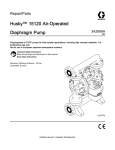
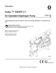
Husky™ 1050HP 2:1
Air-Operated Diaphragm Pump
334390A
EN
1–inch high-pressure pump with modular air valve for fluid transfer applications. For professional use
only.
Important Safety Instructions
Read all warnings and instructions in this manual and in your
Operation manual. Save these instructions.
Maximum Fluid Working Pressure:
200 psi (1.38 MPa, 13.8 bar)
Maximum Air Input Pressure:
100 psi (0.69 MPa, 6.9 bar)
PROVEN QUALITY. LEADING TECHNOLOGY.
Contents
Configuration Number Matrix ............................... 4
Replace Seals or Rebuild the High/Low
Valve ............................................. 15
Check Valve Repair ..................................... 16
Diaphragm and Center Section Repair ........... 17
Warnings ........................................................... 5
Torque Instructions ............................................. 21
Troubleshooting.................................................. 8
Parts.................................................................. 22
Repair................................................................ 10
Pressure Relief Procedure............................ 10
Replace Complete Air Valve ......................... 10
Replace Seals or Rebuild Air Valve ............... 12
Replace Complete High/Low Valve ............... 14
Technical Data ................................................... 40
Related Manuals ................................................ 2
Ordering Information ........................................... 3
Fluid Temperature Range.................................... 41
Graco Standard Husky Pump Warranty................ 42
Related Manuals
Manual No.
Description
334014
Husky 1050HP 2:1 Air-Operated Diaphragm Pump, Operation
2
334390A
Ordering Information
Ordering Information
To Find Your Nearest Distributor
Distributor Note
1. Visit www.graco.com.
1. To find part numbers for replacement parts:
2. Click on Where to Buy and use the Distributor
Locator.
To Specify the Configuration of a New
Pump
Please call your distributor.
a. Use the 20–digit number from the ID plate
on the pump.
b. Use the Configuration Number Matrix on the
next page to understand which parts are
described by each digit.
c.
Refer to the main Parts illustration and to the
Parts/Kits Quick Reference. Follow the page
references on these two pages for further
ordering information, as needed.
2. Please call Graco Customer Service to order.
To Order Replacement Parts
Please call your distributor.
334390A
3
Configuration Number Matrix
Configuration Number Matrix
Check the identification plate (ID) for the 20–digit
Configuration Number of your pump. Use the
following matrix to define the components of your
pump.
Sample Configuration Number:
1050HP A01A
A1
Pump Model
Center Section Manifolds
and Air Valve
Pump
Center Section and Air Valve
Material
1050HP
Aluminum
Aluminum
SS
SP
SP
PT
Seats
Balls
Diaphragms
Manifold
O-Rings
A01A
Air Valve
Manifolds
Standard
A1
Aluminum, standard ports, npt
A2
Aluminum, standard ports, bsp
S1
Stainless steel, standard ports, npt
S2
Stainless steel, standard ports, bsp
Check Valve Seats
Check Valve Balls
Diaphragm Material
Manifold O-Rings
SS
SP
SP
PT
4
316 Stainless Steel
Santoprene
Santoprene
PTFE
334390A
Warnings
Warnings
The following warnings are for the setup, use, grounding, maintenance, and repair of this equipment. The
exclamation point symbol alerts you to a general warning and the hazard symbols refer to procedure-specific
risks. When these symbols appear in the body of this manual or on warning labels, refer back to these
Warnings. Product-specific hazard symbols and warnings not covered in this section may appear throughout
the body of this manual where applicable.
WARNING
FIRE AND EXPLOSION HAZARD
Flammable fumes, such as solvent and paint fumes, in work area can ignite or explode. To help
prevent fire and explosion:
• Use equipment only in well ventilated area.
• Eliminate all ignition sources; such as pilot lights, cigarettes, portable electric lamps, and
plastic drop cloths (potential static arc).
• Keep work area free of debris, including solvent, rags and gasoline.
• Do not plug or unplug power cords, or turn power or light switches on or off when flammable
fumes are present.
• Ground all equipment in the work area. See Grounding instructions.
• Use only grounded hoses.
• Hold gun firmly to side of grounded pail when triggering into pail. Do not use pail liners unless
they are antistatic or conductive.
• Stop operation immediately if static sparking occurs or you feel a shock. Do not use
equipment until you identify and correct the problem.
• Keep a working fire extinguisher in the work area.
• Route exhaust away from all ignition sources. If diaphragm ruptures, fluid may be exhausted
with air.
PRESSURIZED EQUIPMENT HAZARD
Fluid from the equipment, leaks, or ruptured components can splash in the eyes or on skin
and cause serious injury.
• Follow the Pressure Relief Procedure when you stop spraying/dispensing and before
cleaning, checking, or servicing equipment.
• Tighten all fluid connections before operating the equipment.
• Check hoses, tubes, and couplings daily. Replace worn or damaged parts immediately.
334390A
5
Warnings
WARNING
EQUIPMENT MISUSE HAZARD
Misuse can cause death or serious injury.
• Do not operate the unit when fatigued or under the influence of drugs or alcohol.
• Do not exceed the maximum working pressure or temperature rating of the lowest rated
system component. See Technical Data in all equipment manuals.
• Use fluids and solvents that are compatible with equipment wetted parts. See Technical Data
in all equipment manuals. Read fluid and solvent manufacturer’s warnings. For complete
information about your material, request MSDS from distributor or retailer.
• Do not leave the work area while equipment is energized or under pressure.
• Turn off all equipment and follow the Pressure Relief Procedure when equipment is not in use.
• Check equipment daily. Repair or replace worn or damaged parts immediately with genuine
manufacturer’s replacement parts only.
• Do not alter or modify equipment. Alterations or modifications may void agency approvals
and create safety hazards.
• Make sure all equipment is rated and approved for the environment in which you are using it.
• Use equipment only for its intended purpose. Call your distributor for information.
• Route hoses and cables away from traffic areas, sharp edges, moving parts, and hot surfaces.
• Do not kink or over bend hoses or use hoses to pull equipment.
• Keep children and animals away from work area.
• Comply with all applicable safety regulations.
THERMAL EXPANSION HAZARD
Fluids subjected to heat in confined spaces, including hoses, can create a rapid rise in pressure
due to the thermal expansion. Over-pressurization can result in equipment rupture and serious
injury.
• Open a valve to relieve the fluid expansion during heating.
• Replace hoses proactively at regular intervals based on your operating conditions.
PLASTIC PARTS CLEANING SOLVENT HAZARD
Many solvents can degrade plastic parts and cause them to fail, which could cause serious
injury or property damage.
• Use only compatible water-based solvents to clean plastic structural or pressure-containing
parts.
• See Technical Data in this and all other equipment instruction manuals. Read fluid and
solvent manufacturer’s MSDSs and recommendations.
6
334390A
Warnings
WARNING
TOXIC FLUID OR FUMES HAZARD
Toxic fluids or fumes can cause serious injury or death if splashed in the eyes or on skin,
inhaled, or swallowed.
• Read MSDSs to know the specific hazards of the fluids you are using.
• Route exhaust away from work area. If diaphragm ruptures, fluid may be exhausted into
the air.
• Store hazardous fluid in approved containers, and dispose of it according to applicable
guidelines.
BURN HAZARD
Equipment surfaces and fluid that’s heated can become very hot during operation. To avoid
severe burns:
• Do not touch hot fluid or equipment.
PERSONAL PROTECTIVE EQUIPMENT
Wear appropriate protective equipment when in the work area to help prevent serious injury,
including eye injury, hearing loss, inhalation of toxic fumes, and burns. This protective
equipment includes but is not limited to:
• Protective eyewear, and hearing protection.
• Respirators, protective clothing, and gloves as recommended by the fluid and solvent
manufacturer.
334390A
7
Troubleshooting
Troubleshooting
Problem
Cause
Solution
Pump cycles but will not prime.
Pump is running too fast, causing
cavitation before prime.
Reduce air inlet pressure or restrict
inlet air with a needle valve.
Check valve ball severely worn or
wedged in seat or manifold.
Replace ball and seat.
Seat severely worn.
Replace ball and seat.
Outlet or inlet clogged.
Unclog.
Inlet or outlet valve closed.
Open.
Inlet fittings or manifolds loose.
Tighten.
Manifold o-rings damaged.
Replace o-rings.
Pump cycles at stall or fails to hold
pressure at stall.
Worn check valve balls, seats, or
o-rings.
Replace.
Pump will not cycle, or cycles once
and stops.
Air valve is stuck or dirty.
Disassemble and clean air valve.
Use filtered air.
Check valve ball severely worn and
wedged in seat or manifold.
Replace ball and seat.
Pilot valve worn, damaged, or
plugged.
Replace pilot valve.
Air valve gasket damaged.
Replace gasket.
Dispensing valve clogged.
Relieve pressure and clear valve.
High/Low valve shift lever is not fully
seated into the High or Low position.
Shift lever all the way into either
High or Low position.
Clogged suction line.
Inspect; clear.
Sticky or leaking check valve balls.
Clean or replace.
Diaphragm ruptured.
Replace.
Restricted exhaust.
Remove restriction.
Pilot valves damaged or worn.
Replace pilot valves.
Air valve damaged.
Replace air valve.
Air valve gasket damaged.
Replace air valve gasket.
Air supply erratic.
Repair air supply.
Exhaust muffler icing.
Use drier air supply.
Pump operates erratically.
8
334390A
Troubleshooting
Problem
Cause
Solution
Air bubbles in fluid.
Suction line is loose.
Tighten.
Diaphragm ruptured.
Replace.
Loose manifolds, damaged seats or
o-rings.
Tighten manifold bolts or replace
seats or o-rings.
Pump cavitation.
Reduce pump speed or suction lift.
Loose diaphragm shaft bolt.
Tighten.
Exhaust air contains fluid being
pumped.
Diaphragm ruptured.
Replace.
Loose diaphragm shaft bolt.
Tighten or replace.
Moisture in exhaust air.
High inlet air humidity.
Use drier air supply.
Pump exhausts excessive air at
stall.
Worn air valve cup or plate.
Replace cup and plate.
Damaged air valve gasket.
Replace gasket.
Damaged pilot valve.
Replace pilot valves.
Worn shaft seals or bearings.
Replace shaft seals or bearings.
Air valve or fluid cover screws loose.
Tighten.
Diaphragm damaged.
Replace diaphragm.
Air valve gasket damaged.
Replace gasket.
High/Low valve shift lever is not fully
seated into the High or Low position.
Shift the lever all the way into either
High or Low position.
Loose manifold screws or fluid cover
screws.
Tighten manifold screws or fluid
cover screws.
Manifold o-rings worn out.
Replace o-rings.
The hoses for the High/Low valve
are not installed correctly.
Install hoses as shown in the figure
on page 10.
Pump leaks air externally.
Pump leaks fluid externally from
joints.
Pump will operate in the Low
pressure setting, but will not operate
in the High pressure setting.
334390A
9
Repair
Repair
Pressure Relief Procedure
Follow the Pressure Relief Procedure
whenever you see this symbol.
Replace Complete Air Valve
Follow these instructions to install Air Valve
Replacement 24W897.
1. Stop the pump. Follow the Pressure Relief
Procedure in the previous section.
2. Disconnect the main air line.
This equipment stays pressurized until pressure
is relieved manually. To help prevent serious
injury from pressurized fluid, such as splashing
in the eyes or on skin, follow the Pressure Relief
Procedure when you stop pumping and before you
clean, check, or service the equipment.
1. Shut off the air supply to the pump.
2. Open the dispensing valve, if used.
3. Shift the High/Low pressure lever back and forth
two times. Leave the lever in the “Low” position
as shown in Fig. 1.
3. Remove four screws (217). Remove the air valve
(212). Remove the six o-rings (208, 209, and
210).
4. To repair the air valve, go to Disassemble the
Air Valve, step 2, in the next section. To install a
replacement air valve, continue with step 5.
5. Align the new o-rings (208, 209, and 210) on the
High/Low manifold, then attach the air valve.
Apply thread lubricant and torque screws (217)
to 75–85 in-lb (8 to 9 N•m).
6. Reconnect the main air line.
Figure 1 High/Low Pressure Lever
4. Open the fluid drain valve (installed on the
system) to relieve all fluid pressure. Have a
container ready to catch the drainage.
10
334390A
Repair
Apply thread lubricant to threads
before assembly.
Torque screws to 75–85 in-lb (8 to
9 N•m).
334390A
11
Repair
Replace Seals or Rebuild Air Valve
Follow these instructions to service the air valve with
one of the available repair kits. Air Valve Seal Kit
parts are marked with a †. Air Valve Repair Kit parts
are marked with a ♦. Air Valve End Cap Kit parts
are marked with a ‡. Kit 24W952 also is available to
replace the 6 o-rings between the air valve and the
High/Low manifold.
1. Use all parts in the repair kits. Clean other parts
and inspect for damage. Replace as needed.
2. Grease the detent cam (304♦) and install into
housing (301).
3. Grease the u-cups (308♦†) and install on the
piston with lips facing toward the center of the
piston.
Disassemble the Air Valve
1. Perform steps 1-3 under
Replace Complete Air Valve, page 10.
2. Use a T8 Torx screwdriver to remove two
screws (309). Remove the valve plate (305), cup
assembly (312-314), spring (311), and detent
assembly (303).
3. Pull the cup (313) off of the base (312). Remove
the o-ring (314) from the cup.
4. Remove the retaining ring (310) from each end
of the air valve. Use the piston (302) to push
the end cap (307) out of one end. Remove the
u-cup seal (308) from the piston. Pull the piston
out of the end and remove the other u-cup seal
(308). Remove the other end cap (307) and the
end cap o-rings (306).
5. Remove the detent cam (304) from the air valve
housing (301).
Reassemble the Air Valve
Lips face
down.
Lips face
up.
4. Grease both ends of the piston (302♦) and the
housing bore. Install the piston in the housing
(301), with the flat side toward the cup (313♦).
Be careful not to tear u-cups (308♦†) when
sliding piston into housing.
5. Grease new o-rings (306♦†‡) and install on the
end caps (307‡). Install the end caps into the
housing.
6. Install a retaining ring (310‡) on each end to hold
end caps in place.
NOTE: Apply lithium-based grease when instructed
to grease. Order Graco PN 111920.
12
334390A
Repair
7. Grease and install the detent assembly (303♦)
into the piston. Install the o-ring (314♦) on the
cup (313♦). Apply a light film of grease to the
outside surface of the o-ring and the inside
mating surface of the base (312♦).
Orient the end of the base that has a magnet
toward the end of the cup that has the larger
cutout. Engage the opposite end of the parts.
Leave the end with the magnet free. Tilt the base
toward the cup and fully engage the parts, using
care so that the o-ring remains in place. Install
the spring (311♦) onto the protrusion on the cup.
Align the magnet in the base with the air inlet and
install the cup assembly.
8. Grease the cup side and install the valve plate
(305♦). Align the small hole in the plate with the
air inlet. Tighten the screws (309♦†) to hold it
in place.
9. Follow steps 5–6 under
Replace Complete Air Valve, page 10 to replace
the seals and reattach the air valve.
Apply lithiumbased grease.
U-cup lips must
face piston.
Apply lithiumbased grease to
contact surface.
Air inlet.
334390A
13
Repair
Replace Complete High/Low Valve
1. Stop the pump. Follow the
Pressure Relief Procedure, page 10.
2. Disconnect the main air line. Release the quick
disconnect fittings to remove the air manifold
hoses (108).
3. Remove four screws (217). Remove the air valve
(212). Remove the six o-rings (208, 209, and
210).
4. Remove four screws (217). Remove the
High/Low valve (211) and gasket (213).
5. To repair the High/Low valve, go to Disassemble
the High/Low Valve, step 2, in the next section.
To install a replacement air valve, continue with
step 6.
6. Align the new gasket (213) on the primary center
section, then attach the new High/Low valve
(211). Apply thread lubricant and torque screws
(217) to 75–85 in-lb (8 to 9 N•m).
7. Align the new o-rings (208, 209, and 210) on the
High/Low manifold, then attach the air valve.
Apply thread lubricant and torque screws (217)
to 75–85 in-lb (8 to 9 N•m).
8. Reconnect the main air line and the air manifold
hoses (108).
Apply thread lubricant to threads before
assembly.
Torque screws to 75–85 in-lb (8 to 9 N•m).
14
334390A
Repair
Replace Seals or Rebuild the
High/Low Valve
3. Place the spool (404) on the manifold block.
Then grease and install three o-rings (402 and
405) on the spool.
Follow these instructions to service the High/Low
valve. High/Low Valve Seal Kit 24W949 is available
to replace o-rings 402 and 405. Kit 24W952 also is
available to replace the 6 o-rings between the air
valve and the High/Low manifold. Kit 24W950 is
available to replace the spool (404).
4. Use two screws (407) to reattach the High/Low
valve. Torque to 340–360 in-lb (38–41 N•m).
5. Follow steps 7–8 under
Replace Complete High/Low Valve, page 14,
to replace the seals and reattach the High/Low
valve assembly.
Disassemble the High/Low Valve
1. Follow steps 1–4 under
Replace Complete High/Low Valve, page 14.
2. Use a 5/16 in Allen wrench to remove two screws
(407).
3. Remove the High/Low valve (406), two o-rings
(402), one o–ring (405),the spool (404), and two
more o-rings (402).
NOTE: The High/Low manifold block does not
have to be removed from the primary center
section.
Reassemble the High/Low Valve
Apply lithium-based grease.
NOTE: Apply lithium-based grease when instructed
to grease.
Torque to 340–360 in-lb (38–41 N•m).
1. Use all parts in the seal kit. Clean other parts
and inspect for damage. Replace as needed.
2. Grease two o-rings (402) and install them in the
manifold block (401).
334390A
15
Repair
Check Valve Repair
NOTE: Kits are available for new check valve balls
and seats. See Seats and Check Balls
to order kits in the material(s) desired. O-ring and
fastener kits also are available.
NOTE: To ensure proper seating of the check balls,
always replace the seats when replacing the balls.
Also, replace the o-rings every time the manifold is
removed.
Disassemble the Check Valve
1. Follow the Pressure Relief Procedure, page 10.
Disconnect all hoses.
2. Remove the pump from its mounting.
3. Use a 10 mm socket wrench to remove the
manifold fasteners (5), then remove the outlet
manifold (3).
4. Remove the o-rings (9), seats (7), and balls (8).
5. Turn the pump over and remove the inlet
manifold (4).
6. Remove the o-rings (9), seats (7), and balls (8).
Reassemble the Check Valve
1. Clean all parts and inspect for wear or damage.
Replace parts as needed.
2. Reassemble in the reverse order, following all
notes in the illustration. Put the inlet manifold on
first. Be sure the ball checks (7-9) and manifolds
(3, 4) are assembled exactly as shown. The ball
must seat on the chamfered side of the seat.
The arrows (A) on the fluid covers (2) must point
toward the outlet manifold (3).
16
Figure 2 Check valve assembly
Torque to 105 to 115 in-lb
(12 to 13 N·m). Follow torque sequence.
See Torque Instructions, page 21.
Arrow (A) must point toward outlet
manifold
The chamfered side of the seat must face
the ball.
334390A
Repair
Diaphragm and Center Section Repair
secondary air module. Bearings (203) can
remain in place.
NOTE: See Diaphragms
for replacement diaphragm kits. Center Rebuild
Kit 24W946 also is available. Parts included in the
Center Rebuild Kit are marked with an *. For best
results, use all kit parts.
Disassemble the Fluid Diaphragms
1. Follow the Pressure Relief Procedure, page 10.
2. Remove the manifolds and disassemble
the ball check valves as explained in
Check Valve Repair, page 16.
3. Use a 10 mm socket wrench to remove the fluid
cover screws (5), then pull one of the fluid covers
(2) off the pump. Then, remove the other fluid
cover.
4. Remove the bolt (14) from the diaphragm shaft
on one side of the pump. If the diaphragm
shaft bolt (14) remains attached to the shaft
(206), remove it. Then, remove all parts of that
diaphragm assembly.
5. Follow the same procedure to disassemble the
other diaphragm assembly.
6. If either shaft is still attached to the set screw
(104), use a wrench on the flats of the shaft to
remove.
Disassemble the Center Section
1. Use a 10 mm socket wrench to remove the
screws (5), then separate the primary air module
(101) from the secondary air module (102).
2. Remove the diaphragm (109), the air plates (103
and 105), and the set screw (104).
3. Inspect the diaphragm shafts (206) for wear or
scratches. If damaged, inspect the bearings
(203) in place. If they are damaged, use a
bearing puller to remove them.
NOTE: Do not remove undamaged bearings.
4. Use an o-ring pick to remove the u-cup packings
(202) from the primary air module and the
334390A
5. If necessary, use a socket wrench to remove
the pilot valves (205, primary air module) or
the secondary pilot plugs (220, secondary air
module).
6. Remove the pilot valve cartridges only if
necessary due to a known or suspected problem.
After removing pilot valves (primary side) or
secondary pilot plugs (secondary side), use a
hex to remove the cartridges (204), then remove
cartridge o-rings (219). If stripped, use two
screwdrivers to screw out the cartridge.
NOTE: Do not remove undamaged pilot valve
cartridges.
Reassemble the Center Section
Follow all notes in the illustrations. These notes
contain important information.
NOTE: Apply lithium-based grease whenever
instructed to grease.
1. Clean all parts and inspect for wear or damage.
Replace parts as needed.
NOTE: Follow Steps 2–5 for both the Primary Air
Module and the Secondary Air Module.
2. If removed, grease and install the new pilot valve
cartridges (204*) and cartridge o-rings (219*).
Screw in until seated.
NOTE: Cartridges (204*) must be installed before
pilot valves (205*) or secondary pilot plugs (220*).
3. Grease and install the pilot valves (205*, primary
side) or secondary pilot plugs (220*, secondary
side). Torque to 20–25 in-lb (2–3 N•m) at 100
rpm maximum. Do not overtorque.
4. Grease and install the diaphragm shaft u-cup
packings (202*) so the lips face out of the
housing.
5. If removed, insert the new bearings (203*) into
the primary air module and/or the secondary
air module. Use a press or a block and rubber
mallet to press-fit the bearing so it is flush with
the surface of the module.
17
Repair
Reassemble the Fluid Diaphragms
Follow all notes in the illustration. These notes
contain important information.
NOTE: Apply lithium-based grease whenever
instructed to grease.
1. Assemble the primary side air plate (105*), the
center diaphragm (109*), and the secondary side
air plate (103*) on the set screw (104*). Install a
shaft (206*) on each end.
2. Grease the shaft u-cups (202*) and the length of
both diaphragm shafts (206*). Slide the shaft on
the secondary side (closest to air plate 103*) into
the secondary air module.
3. Slide the primary air module onto the primary
side shaft (closest to air plate 105*).
5. Assemble the washer (28), the fluid side
diaphragm plate (10), the diaphragm (12), and
the air side diaphragm plate (11), on a diaphragm
shaft bolt (14), exactly as shown.
6. Apply primer and medium-strength (blue) thread
locker to the threads of the bolt (14). Screw the
assembly into the shaft of the secondary air
module hand-tight.
7. Repeat for the other diaphragm assembly and
install on the primary air module.
8. Hold one of the bolts with a wrench, and torque
the other bolt to 20–25 ft-lb (27–34 N•m) at 100
rpm maximum. Do not over-torque.
4. Install the diaphragm joint bolts (5).
Torque to 110 in-lb (11.3 N•m). Follow
Torque Instructions, page 21.
Rounded side faces diaphragm.
Apply lithium based grease.
Apply primer and medium-strength
(blue) thread locker. Torque to 20–25
ft-lb (27–34 N•m) at 100 rpm maximum.
AIR SIDE markings on fluid diaphragms
must face center housing.
AIR SIDE markings on center
diaphragm must face the primary air
module.
Lips must face out of housing.
Cartridges (204) must be installed
before pilot valves (205) or secondary
pilot plugs (220).
Torque to 20-25 in.-lb (2-3 N•m).
Torque to 110 in.-lb (11.3 N•m). Follow
Torque Instructions, page 21.
18
334390A
Repair
Primary Air Module
Secondary Air Module
334390A
19
Repair
9. Reattach the secondary side fluid cover (2).
The arrow must point toward the air valve. See
Torque Instructions, page 21.
To avoid injury, keep your fingers away from
the moving diaphragms when air pressure is
applied.
10. To ensure proper seating and extend diaphragm
life, apply air pressure to the pump prior to
attaching the fluid cover on the primary air
module.
a. Place the supplied tool on top of the air valve
gasket (213). Arrows (A) must face toward
the fluid cover that is already attached.
c.
Supply a minimum of 20 psi (0.14 MPa, 1.4
bar) air pressure to the air valve. Shop air
may be used. The diaphragm will shift so the
second fluid cover will seat properly. Keep
air pressure on until the second fluid cover
is attached.
d. Attach the second fluid cover (2). See
Torque Instructions, page 21.
e. Remove the air valve and the tool. Verify that
the gasket (213), is in place, and reattach the
air valve. See Torque Instructions, page 21.
NOTE: These steps must be followed
anytime the fluid covers are removed.
f.
Reassemble the ball check valves
and manifolds as explained in
Check Valve Repair, page 16.
Figure 3 Fluid cover tool
b. Reattach the air valve.
20
334390A
Torque Instructions
Torque Instructions
NOTE: All fasteners for the fluid covers, center
diaphragm joint, and manifolds have a thread-locking
adhesive patch applied to the threads. If this patch is
excessively worn, the fasteners may loosen during
operation. Replace screws with new ones or apply
medium-strength (blue) Loctite or equivalent to the
threads.
Fluid cover, center diaphragm joint, and manifold
fasteners: 100 in-lb (11.3 N•m)
Lubricate air valve fasteners prior to reassembly to
prevent galling. Retorque the air valve fasteners (V)
in a crisscross pattern to specified torque.
Air valve fasteners: 80 in-lb (9.0 N•m)
If fluid cover, center diaphragm joint, or manifold
fasteners have been loosened, it is important to
torque them using the following procedure to improve
sealing.
NOTE: Always completely torque the fluid covers and
the center diaphragm joint before torquing manifolds.
Start all fluid cover or center diaphragm joint screws a
few turns. Then turn down each screw just until head
contacts cover. Then turn each screw by 1/2 turn
or less working in a crisscross pattern to specified
torque. Repeat for manifolds.
Air Valve Fasteners
Fluid Covers and Center Diaphragm Joint
334390A
Manifolds
21
Parts
Parts
22
334390A
Parts
Parts/Kits Quick Reference
Use this table as a quick reference for parts/kits. Go to the pages indicated in the table for a full description of
kit contents.
Ref.
Part/Kit
Description
Qty.
Ref.
Part/Kit
Description
Qty.
1
–——
CENTER SECTION;
Aluminum, not sold
separately. See page
1
7
24B637
SEATS; stainless steel,
4-pack, see page 37
1
8
24B646
BALLS, valve, check;
4–pack; Santoprene; see
1
24.
2
24X053
COVER, fluid, kit; stainless 2
steel, see page 36
MANIFOLD, outlet, kit; see 1
3
page 36
24W833
Aluminum, npt
24W834
Aluminum, bspt
24W837
Stainless steel, npt
24W838
Stainless steel, bspt
MANIFOLD, inlet, kit; see
4
page 36
page 37
24B655
10
———
PLATE, fluid side
diaphragm; included in
Air and Fluid Plate Kit
24C035, see page 38
11
———
PLATE, air side diaphragm 2
; included in Air and Fluid
Plate Kit 24C035; see page
1
38
DIAPHRAGM, kit; 2–pack,
Santoprene see page 38
1
14
189044
BOLT, M12–1.75 x 35 mm
2
18
24D642
MUFFLER, kit; includes
o-ring and mounting
hardware
1
BOLT, M8 x 1.25 x 25 mm, 2
for aluminum manifolds,
includes nuts, package of 8
19
188621▲ LABEL, warning
27
-——
NUT, included with Ref. 5, 2
in packages of 8
2
28
-——
O-RING, included in
diaphragm kits
30
17C772▲ TAG, warning, torque
instructions
1
35
198382▲ LABEL, warning,
multilingual
1
24W836
Aluminum, bspt
24W839
Stainless steel, npt
24W840
Stainless steel, bspt
FASTENERS, see page 36
24C064
24B654
6
BOLT, M8 x 1.25 x 20
mm, for stainless steel
manifolds, includes nuts,
package of 8
BOLT, M8 x 1.25 x 25 mm, 3
for fluid covers and bolting
center sections together,
package of 8
PLUG, Manifold, Kit;
used only on aluminum
manifolds; includes 6
24C617
For npt manifolds
24C618
For bsp manifolds
1
2
1
▲ Replacement Warning labels, signs, tags, and
cards are available at no cost.
334390A
2
24B628
Aluminum, npt
24X051
page 39
12
24W835
5
O-RING, seat; 8–pack, see 1
9
- — — These parts are not sold separately.
23
Parts
Center Section
Sample Configuration Number
Pump
Model
Center
Section and
Air Valve
Fluid
Covers and
Manifolds
Seats
Balls
Diaphragms
Seat and
Manifold
Seal
1050HP
A01A
A1
SS
SP
SP
PT
Description
Qty
FITTING, air, 1/2 npt x 1/2 T, see
4
HOSE, air; 15 in. segment, see
2
DIAPHRAGM, Santoprene
1
Description
Qty
Ref
AIR MODULE, primary, see page
1
107
AIR MODULE, secondary, see page
1
108
PLATE, air, secondary side
1
109*
104*
SCREW, set, M12
1
* Parts included in Center Section Rebuild
105*
PLATE, air, primary side
1
Ref
101
102
103*
24
26
28
page 30
page 30
Kit. See page 30.
334390A
Parts
Notes
334390A
25
Parts
Primary Air Module
Sample Configuration Number
Pump
Model
Center
Section and
Air Valve
Fluid
Covers and
Manifolds
Seats
Balls
Diaphragms
Seat and
Manifold
Seal
1050HP
A01A
A1
SS
SP
SP
PT
26
334390A
Parts
Ref
Description
Qty
Ref
Description
Qty
201
1
210
2
211
O-RING, Buna-N, 1.125 in. (29 mm)
OD, see page 31
VALVE, High/Low, see page 35
3
202*
HOUSING, center, not sold
separately
U-CUP, center shaft
1
203*
BEARING, center shaft
2
212
VALVE, air, see page 32
1
204*
CARTRIDGE, pilot receiver
2
213*
GASKET, air valve
1
205*
VALVE, pilot
2
217*
SCREW, M6 x 25, thread forming
8
206*
SHAFT, center
1
219*
2
207
SCREW, ground, Order PN 116343
1
O-RING, receiver cartridge, Buna-N,
0.9 in. (23 mm) OD
208
O-RING, Buna-N, 3.2 in. (81 mm)
OD, see page 31
O-RING, Buna-N, 0.35in. (9 mm)
OD, see page 31
1
209
334390A
* Parts included in Center Section Rebuild
Kit. See page 30.
2
27
Parts
Secondary Air Module
Sample Configuration Number
Pump
Model
Center
Section and
Air Valve
Fluid
Covers and
Manifolds
Seats
Balls
Diaphragms
Seat and
Manifold
Seal
1050HP
A01A
A1
SS
SP
SP
PT
28
334390A
Parts
Ref
Description
Qty
Ref
Description
Qty
201
1
213*
GASKET, air valve
1
202*
HOUSING, center, not sold
separately
U-CUP, center shaft
216
PLUG, pipe, order PN 102726
1
203*
BEARING, center shaft
2
217*
SCREW, M6 x 25, thread forming
4
204*
CARTRIDGE, pilot receiver
2
219*
2
206*
SHAFT, center
1
220*
O-RING, receiver cartridge, Buna-N,
0.9 in. (23 mm) OD
PLUG, secondary pilot
207
SCREW, ground, order PN 116343
1
* Parts included in Center Section Rebuild
214
PLATE, adapter, see page 31
1
334390A
2
2
Kit. See page 30.
29
Parts
Center Section Kits
Sample Configuration Number
Pump
Model
Center
Section and
Air Valve
Fluid
Covers and
Manifolds
Seats
Balls
Diaphragms
Seat and
Manifold
Seal
1050HP
A01A
A1
SS
SP
SP
PT
Center Section Rebuild Kit 24W946
Kit includes:
Pilot Valve Assembly Kit 24B657
Kit includes:
• 2 center shaft (206)
• 2 pilot valve assemblies (205)
• 4 center shaft bearings (203)
• 2 receiver cartridges (204)
• 4 center shaft u-cups (202)
• 2 receiver cartridge o-rings (219)
• 2 air valve gasket (213)
• 1 grease packet
• 8 screws (217)
• 8 seat o-rings (9)
Secondary Pilot Plug Assembly Kit 24X057
Kit includes:
• 2 pilot valves (205)
• 2 secondary pilot plug assemblies (220)
• 2 secondary pilot plugs (220)
• 2 receiver cartridges (204)
• 4 pilot valve receiver cartridges (204)
• 2 receiver cartridge o-rings (219)
• 4 receiver cartridge o-rings (219)
• 1 grease packet
• 1 grease packet
• 1 air plate, secondary side (103)
Center Shaft Kit 24B656
• 1 air plate, primary side (105)
NOTE: Purchase 2 kits if you are rebuilding both the
primary and secondary air modules.
• 1 set screw, M12 (104)
• 1 diaphragm, Santoprene (109)
Kits include:
• 2 center shaft u-cups (202)
Hose and Fitting Kit 24W947
Kit includes:
• 1 center shaft (206)
• 4 air fittings (107)
• 1 grease packet
• 2 center shaft bearings (203)
• 2 air hoses (108)
Center Shaft Bearing Kit 24B658
Center Diaphragm Kit 24W953
Kit includes:
NOTE: Purchase 2 kits if you are rebuilding both the
primary and secondary air modules.
• 1 air plate, secondary side (103)
Kit includes:
• 1 air plate, primary side (105)
• 2 center shaft u-cups (202)
• 1 set screw, M12 (104)
• 2 center shaft bearings (203)
• 1 diaphragm, Santoprene (109)
• 1 grease packet
30
334390A
Parts
High/Low Manifold Seals Kit 24W952
Kit includes:
Adapter Plate Kit 24W951
Kit includes:
• 1 o-ring (208)
• 1 adapter plate (214)
• 2 o-rings (209)
• 4 screws (217)
• 3 o-rings (210)
• 1 air valve gasket (213)
• 1 air valve gasket (213)
334390A
31
Parts
Air Valve
Sample Configuration Number
Pump
Model
Center
Section and
Air Valve
Fluid
Covers and
Manifolds
Seats
Balls
Diaphragms
Seat and
Manifold
Seal
1050HP
A01A
A1
SS
SP
SP
PT
32
334390A
Parts
Ref
Description
Qty
Ref
Description
Qty
301
HOUSING, not sold
separately
PISTON
1
308✦✝
U-CUP, carboxylated nitrile
2
302✦
1
303✦
PISTON ASSEMBLY, detent
1
304✦
CAM, detent
1
305✦
PLATE, air valve
1
306✦✝‡
O-RING
2
307‡
CAP, end
2
✦ Parts included in Air Valve Repair Kit.
309✦✝
SCREW, M3, thread forming
2
310‡
RETAINING RING
2
311✦
SPRING, detent
1
312✦
BASE, cup
1
313✦
CUP
1
314✦
O-RING, cup
1
‡ Parts included in Air Valve End Cap Kit.
✝ Parts included in Air Valve Seals Kit..
334390A
33
Parts
Sample Configuration Number
Pump
Model
Center
Section and
Air Valve
Fluid
Covers and
Manifolds
Seats
Balls
Diaphragms
Seat and
Manifold
Seal
1050HP
A01A
A1
SS
SP
SP
PT
✝ Air Valve Seals Kit 24K859
Air Valve Replacement Kit 24W897
Kit includes:
Kit includes:
• 2 end cap o-rings (306)
• 1 air valve assembly (212)
• 2 piston u-cups (308)
• 1 o-ring (208)
• 2 screws, M3, shorter (309)
• 2 o-rings (209)
• 2 screws, #4, longer (not used)
• 3 o-rings (210)
• 1 air valve gasket (213)
• 4 screws (217)
• 1 grease packet
• 1 solenoid release button o-ring (not shown, not
used)
✦ Air Valve Repair Kit 24K860
Kit includes:
• 1 air valve piston (302)
‡ Air Valve End Cap Kit 24A361
Kit includes:
• 2 end caps (307)
• 2 retaining rings (310)
• 2 o-rings (306)
• 1 detent piston assembly (303)
• 1 detent cam (304)
• 1 air valve plate (305)
• 2 end cap o-rings (306)
• 2 piston u-cups (308)
• 2 screws, M3, shorter (309)
• 2 screws, #4, longer (not used)
• 1 detent spring (311)
• 1 air cup base (312)
• 1 air cup (313)
• 1 air cup o-ring (314)
• 1 solenoid release button o-ring (not shown, not
used)
• 1 air valve gasket (213)
• 1 grease packet
34
334390A
Parts
High/Low Valve
Sample Configuration Number
Pump
Model
Center
Section and
Air Valve
Fluid
Covers and
Manifolds
Seats
Balls
Diaphragms
Seat and
Manifold
Seal
1050HP
A01A
A1
SS
SP
SP
PT
Ref
Description
Qty
Ref
Description
Qty
401
PLATE, adapter, not sold separately
1
406
1
402
O-RING, PTFE, 0.8 in. (20 mm) OD
4
403
LEVER, HIGH-LOW shift
1
404
SPOOL
1
CAP, adapter plate, not sold
separately
SCREW, cap, socket head, 3/8–16
x 2.25; order PN 114666
405
O-RING, PTFE, 1.9 in. (48 mm) OD
1
407
High/Low Valve Replacement Kit 24W948
High/Low Valve Spool Kit 24W950
Kit includes:
Kit includes:
• 1 High/Low valve assembly (211)
• 1 Spool (404)
• 1 air valve gasket (213)
• 4 o-rings (402)
• 4 screws (217)
• 1 o-ring (405)
• 1 grease packet
• 1 lever (403)
High/Low Valve Seals Kit 24W949
2
• 1 grease packeet
Kit includes:
• 4 o-rings (402)
• 1 o-ring (405)
• 1 grease packet
334390A
35
Parts
Fluid Covers and Manifolds
Sample Configuration Number
Pump
Model
Center
Section and
Air Valve
Fluid
Covers and
Manifolds
Seats
Balls
Diaphragms
Seat and
Manifold
Seal
1050HP
A01A
A1
SS
SP
SP
PT
Fluid Cover Kit 24X053
Stainless Steel Outlet Manifold Kits
Kit includes:
S1 (npt)
24W837
• 1 fluid cover (2)
S2 (bsp)
24W838
• 4 o-rings (9), PTFE
Aluminum Outlet Manifold Kits
A1 (npt)
24W833
A2 (bsp)
24W834
Kits include:
• 1 outlet manifold (3)
• 4 o-rings (9), PTFE
• 1 warning label
Kits include:
• 1 outlet manifold (3)
• 1 pipe plug (6)
Stainless Steel Inlet Manifold Kits
S1 (npt)
24W839
S2 (bsp)
24W840
• 4 o-rings(9), PTFE
• 1 warning label
Aluminum Inlet Manifold Kits
A1 (npt)
24W835
A2 (bsp)
24W836
Kits include:
• 1 inlet manifold (4)
• 4 o-rings (9), PTFE
Fastener Kits
Kits include:
A1, A2
24X051
S1, S2
24C064
All Models
Order Kit 24B654 for fluid covers
and bolting the two air modules
together, includes 8 bolts
• 1 inlet manifold (4)
• 1 pipe plug (6)
Kits include:
• 4 o-rings (9), PTFE
• 8 screws, (5)
• 8 nuts (27, Kits 24X051 and 24C064)
36
334390A
Parts
Seats and Check Balls
Sample Configuration Number
Pump
Model
Center
Section and
Air Valve
Fluid
Covers and
Manifolds
Seats
Balls
Diaphragms
Seat and
Manifold
Seal
1050HP
A01A
A1
SS
SP
SP
PT
Seat Kits
SS
24B637
Ball Kits
SP
24B646
Kit includes:
Kit includes:
• 4 seats (7), stainless steel
• 4 balls (8), Santoprene
• 8 o-rings, PTFE (9)
• 8 o-rings, PTFE (9)
334390A
37
Parts
Diaphragms
Sample Configuration Number
Pump
Model
Center
Section and
Air Valve
Fluid
Covers and
Manifolds
Seats
Balls
Diaphragms
Seat and
Manifold
Seal
1050HP
A01A
A1
SS
SP
SP
PT
1–Piece Bolt-Through
Diaphragm Kits
SP
24B628
Air and Fluid Plate Kit 24C035
Kit includes:
• 1 air side diaphragm plate (11)
Kits include:
• 1 fluid side diaphragm plate (10)
• 8 o-rings, PTFE (9)
• 1 o-ring (28)
• 2 diaphragms (12), material indicated in table
• 1 bolt (14)
• 2 o-rings for the bolt (28)
• 1 diaphragm install tool
• 1 packet anaerobic adhesive
38
334390A
Parts
Manifold Seals
Sample Configuration Number
Pump
Model
Center
Section and
Air Valve
Fluid
Covers and
Manifolds
Seats
Balls
Diaphragms
Seat and
Manifold
Seal
1050HP
P01A
P1
SS
SP
SP
PT
Manifold O-Ring Kits
All Models
24W212
Kits include:
• 8 o-rings (9), PTFE
334390A
39
Technical Data
Technical Data
Metric
US
Maximum fluid working pressure
Air pressure operating range
200 psi
1.4 MPa,14.0 bar
20-100 psi
0.14-0.69 MPa, 1.4-6.9 bar
0.17 g
0.64 l
Fluid displacement per cycle
Low Pressure Setting
0.20 g
0.76 l
at 70 psi, 20 gpm
at 4.8 bar, 76 lpm
Low Pressure Setting
26 scfm
0.7 cubic meters per minute
High Pressure Setting
51 scfm
1.4 cubic meters per minute
High Pressure Setting
Air consumption
Maximum values with water as media under submerged inlet conditions at ambient temperature:
Maximum air consumption
Low Pressure Setting
59 scfm
1.7 cubic meters per minute
High Pressure Setting
95 scfm
2.7 cubic meters per minute
Low Pressure Setting
50 gpm
189 lpm
High Pressure Setting
46 gpm
174 lpm
Maximum free-flow delivery
Maximum pump speed
Low Pressure Setting
280 cpm
High Pressure Setting
225 cpm
Maximum suction lift (varies widely
based on ball/seat selection and
wear, operating speed, material
properties, and other variables)
Maximum size pumpable solids
Recommended cycle rate for continuous
use
Recommended cycle rate for circulation
systems
Air inlet size
16 ft dry,
29 ft wet
4.9 m dry
8.8 m wet
1/8 in
3.2 mm
93–140 cpm
(in Low or High setting)
20 cpm
(in Low or High setting)
3/4 npt(f)
Fluid inlet size
1 in. npt(f) or 1 in. bspt
Fluid outlet size
1 in. npt(f) or 1 in. bspt
Weight
40
48 lb (aluminum manifolds)
60 lb (SST manifolds)
21.8 kg (aluminum manifolds)
27.2 kg (SST manifolds)
334390A
Fluid Temperature Range
Sound Power (measured per ISO-9614–2)
At 70 psi (0.48 MPa, 4.8 bar) and 50 cpm
Low Pressure Setting
78 dBa
High Pressure Setting
91 dBa
At 100 psi (0.7 MPa, 7.0 bar) and full flow
Low Pressure Setting
90 dBa
High Pressure Setting
102 dBa
Sound Pressure (tested 3.28 ft [1 m] from equipment)
At 70 psi (0.48 MPa, 4.8 bar) and 50 cpm
Low Pressure Setting
84 dBa
High Pressure Setting
96 dBa
At 100 psi (0.7 MPa, 7.0 bar) and full flow
Low Pressure Setting
84 dBa
High Pressure Setting
96 dBa
Wetted parts
Non-wetted external parts
aluminum plus the material(s) chosen for seat, ball,
and diaphragm options.
aluminum, coated carbon steel
Fluid Temperature Range
NOTICE
Temperature limits are based on mechanical stress only. Certain chemicals will further limit the fluid
operating temperature range. Stay within the temperature range of the most-restricted wetted component.
Operating at a fluid temperature that is too high or too low for the components of your pump may cause
equipment damage.
Fluid Temperature Range
Diaphragm/Ball Material
Santoprene® (SP)
334390A
Fahrenheit
Celsius
-40° to 180°F
-40° to 82°C
41
Graco Standard Husky Pump Warranty
Graco warrants all equipment referenced in this document which is manufactured by Graco and bearing its
name to be free from defects in material and workmanship on the date of sale to the original purchaser for
use. With the exception of any special, extended, or limited warranty published by Graco, Graco will, for a
period of five years from the date of sale, repair or replace any part of the equipment determined by Graco
to be defective. This warranty applies only when the equipment is installed, operated and maintained in
accordance with Graco’s written recommendations.
This warranty does not cover, and Graco shall not be liable for general wear and tear, or any malfunction,
damage or wear caused by faulty installation, misapplication, abrasion, corrosion, inadequate or improper
maintenance, negligence, accident, tampering, or substitution of non-Graco component parts. Nor shall
Graco be liable for malfunction, damage or wear caused by the incompatibility of Graco equipment
with structures, accessories, equipment or materials not supplied by Graco, or the improper design,
manufacture, installation, operation or maintenance of structures, accessories, equipment or materials
not supplied by Graco.
This warranty is conditioned upon the prepaid return of the equipment claimed to be defective to an
authorized Graco distributor for verification of the claimed defect. If the claimed defect is verified, Graco
will repair or replace free of charge any defective parts. The equipment will be returned to the original
purchaser transportation prepaid. If inspection of the equipment does not disclose any defect in material
or workmanship, repairs will be made at a reasonable charge, which charges may include the costs of
parts, labor, and transportation.
THIS WARRANTY IS EXCLUSIVE, AND IS IN LIEU OF ANY OTHER WARRANTIES, EXPRESS OR
IMPLIED, INCLUDING BUT NOT LIMITED TO WARRANTY OF MERCHANTABILITY OR WARRANTY
OF FITNESS FOR A PARTICULAR PURPOSE.
Graco’s sole obligation and buyer’s sole remedy for any breach of warranty shall be as set forth above.
The buyer agrees that no other remedy (including, but not limited to, incidental or consequential damages
for lost profits, lost sales, injury to person or property, or any other incidental or consequential loss) shall
be available. Any action for breach of warranty must be brought within six (6) years of the date of sale..
GRACO MAKES NO WARRANTY, AND DISCLAIMS ALL IMPLIED WARRANTIES OF
MERCHANTABILITY AND FITNESS FOR A PARTICULAR PURPOSE, IN CONNECTION WITH
ACCESSORIES, EQUIPMENT, MATERIALS OR COMPONENTS SOLD BUT NOT MANUFACTURED BY
GRACO. These items sold, but not manufactured by Graco (such as electric motors, switches, hose, etc.),
are subject to the warranty, if any, of their manufacturer. Graco will provide purchaser with reasonable
assistance in making any claim for breach of these warranties..
In no event will Graco be liable for indirect, incidental, special or consequential damages resulting from
Graco supplying equipment hereunder, or the furnishing, performance, or use of any products or other
goods sold hereto, whether due to a breach of contract, breach of warranty, the negligence of Graco, or
otherwise.
FOR GRACO CANADA CUSTOMERS
The Parties acknowledge that they have required that the present document, as well as all documents,
notices and legal proceedings entered into, given or instituted pursuant hereto or relating directly or
indirectly hereto, be drawn up in English. Les parties reconnaissent avoir convenu que la rédaction du
présente document sera en Anglais, ainsi que tous documents, avis et procédures judiciaires exécutés,
donnés ou intentés, à la suite de ou en rapport, directement ou indirectement, avec les procédures
concernées.
Graco Information
For the latest information about Graco products, visit www.graco.com.
For patent information, see www.graco.com/patents.
To place an order, contact your Graco Distributor or call to identify the nearest distributor.
Phone: 612-623-6921 or Toll Free: 1-800-328-0211 Fax: 612-378-3505
All written and visual data contained in this document reflects the latest product information available at the time of publication.
Graco reserves the right to make changes at any time without notice.
Original Instructions. This manual contains English. MM 334390
Graco Headquarters: Minneapolis
International Offices: Belgium, China, Japan, Korea
GRACO INC. AND SUBSIDIARIES • P.O. BOX 1441 • MINNEAPOLIS MN 55440-1441 • USA
Copyright 2014, Graco Inc. All Graco manufacturing locations are registered to ISO 9001.
www.graco.com