1
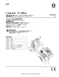
Operation LineLazer IV 250DC Self-Propelled Line Striper For the application of line striping materials. For professional use only. For outdoor use only. Not for use in hazardous locations or explosive atmospheres. Maximum Operating Speed: 10 mph (16 kph) Maximum Operating Pressure: 3300 psi (22.8 MPa, 228 bar) IMPORTANT SAFETY INSTRUCTIONS Read all warnings and instructions in this manual and the engine manual. Be familiar with the controls and the proper usage of the equipment. Save these instructions. Model Guns Pressurized Bead System Description 24U242 2 No LLIV 250DC 24U243 2 Yes LLIV 250DC 24U810 3 No LLIV 250DC 24U820 3 Yes LLIV 250DC Related Manuals: 334053 Repair 334054 Parts 311254 Gun 309277 Pump 312307 Auto-Layout Applications Methods 332230 Pressurized Bead System (PBS) 333388B EN Table of Contents Warnings . . . . . . . . . . . . . . . . . . . . . . . . . . . . . . . . . 3 Component Identification (Striper) . . . . . . . . . . . . 6 Component Identification (Controls) . . . . . . . . . . . 7 Grounding Procedure (For Flammable Materials Only) . . . . . . . . . . . 8 Pressure Relief Procedure . . . . . . . . . . . . . . . . . . . 8 Setup/Startup . . . . . . . . . . . . . . . . . . . . . . . . . . . . . . 9 SwitchTip and Guard Assembly . . . . . . . . . . . . 11 Gun Placement . . . . . . . . . . . . . . . . . . . . . . . . . . . 12 Install Guns . . . . . . . . . . . . . . . . . . . . . . . . . . . . 12 Position Guns . . . . . . . . . . . . . . . . . . . . . . . . . . 12 Gun Arm Mounts . . . . . . . . . . . . . . . . . . . . . . . . 13 Change Gun Position (Front and Back) . . . . . . . . . . . . . . . . . . . . . 13 Change Gun Position (Left and Right) . . . . . . . . . . . . . . . . . . . . . . 13 Gun Cable Adjustment . . . . . . . . . . . . . . . . . . . 15 Change Trigger Position . . . . . . . . . . . . . . . . . . 16 Gun Positions Chart . . . . . . . . . . . . . . . . . . . . . 17 Driving Instructions . . . . . . . . . . . . . . . . . . . . . . . . 18 Parking/Emergency Brake . . . . . . . . . . . . . . . . 19 Drive Engagement . . . . . . . . . . . . . . . . . . . . . . 19 Straight Line Adjustment . . . . . . . . . . . . . . . . . . 19 Handle Bar Height Adjustment . . . . . . . . . . . . . 20 Platform Storage Position . . . . . . . . . . . . . . . . . 20 Front Pad Adjustment . . . . . . . . . . . . . . . . . . . . 20 2 Smart Control Operation . . . . . . . . . . . . . . . . . . . . 21 Menu Tree . . . . . . . . . . . . . . . . . . . . . . . . . . . . . 21 Control Features . . . . . . . . . . . . . . . . . . . . . . . . 22 Main Menus . . . . . . . . . . . . . . . . . . . . . . . . . . . . 23 Initial Setup . . . . . . . . . . . . . . . . . . . . . . . . . . . . 24 Striping Mode . . . . . . . . . . . . . . . . . . . . . . . . . . 26 Measure Mode . . . . . . . . . . . . . . . . . . . . . . . . . . 27 Layout Mode . . . . . . . . . . . . . . . . . . . . . . . . . . . 28 Stall Calculator . . . . . . . . . . . . . . . . . . . . . . . . . 29 Angle Calculator . . . . . . . . . . . . . . . . . . . . . . . . 30 Setup/Information . . . . . . . . . . . . . . . . . . . . . . . 31 Data/Information . . . . . . . . . . . . . . . . . . . . . . . . 32 Information (2) . . . . . . . . . . . . . . . . . . . . . . . . . . 33 World Symbol Key . . . . . . . . . . . . . . . . . . . . . . . . . 35 Cleanup . . . . . . . . . . . . . . . . . . . . . . . . . . . . . . . . . . 36 Hydraulic Oil/Filter Change . . . . . . . . . . . . . . . . . . 37 Removal . . . . . . . . . . . . . . . . . . . . . . . . . . . . . . 37 Installation . . . . . . . . . . . . . . . . . . . . . . . . . . . . . 37 Technical Specifications . . . . . . . . . . . . . . . . . . . . 38 Graco Standard Warranty . . . . . . . . . . . . . . . . . . . 40 333388B Operation Warnings Warnings The following warnings are for the setup, use, grounding, maintenance, and repair of this equipment. The exclamation point symbol alerts you to a general warning and the hazard symbols refer to procedure-specific risks. When these symbols appear in the body of this manual or on warning labels, refer back to these Warnings. Product-specific hazard symbols and warnings not covered in this section may appear throughout the body of this manual where applicable. WARNING TRAFFIC HAZARD Being struck by other vehicles may result in serious injury or death. • Do not operate in traffic. • Use appropriate traffic control in all traffic areas. • Follow local highway and transportation regulations for traffic control (for example: Manual on Uniform Traffic Control Devices, U.S. Department of Transportation). FIRE AND EXPLOSION HAZARD Flammable fumes, such as solvent and paint fumes, in work area can ignite or explode. To help prevent fire and explosion: • Use equipment only in well ventilated area. • Do not fill fuel tank while engine is running or hot; shut off engine and let it cool. Fuel is flammable • and can ignite or explode if spilled on hot surface. • Eliminate all ignition sources; such as pilot lights, cigarettes, portable electric lamps, and plastic drop • cloths (potential static arc). • Keep work area free of debris, including solvent, rags and gasoline. • Do not plug or unplug power cords, or turn power or light switches on or off when flammable fumes • are present. • Ground all equipment in the work area. See Grounding instructions. • Use only grounded hoses. • Hold gun firmly to side of grounded pail when triggering into pail. Do not use pail liners unless they • are antistatic or conductive. • Stop operation immediately if static sparking occurs or you feel a shock. Do not use equipment • until you identify and correct the problem. • Keep a working fire extinguisher in the work area. INJECTION HAZARD High-pressure fluid from gun, hose leaks, or ruptured components will pierce skin. This may look like just a cut, but it is a serious injury that can result in amputation. Get immediate surgical treatment. • Do not spray without tip guard and trigger guard installed. • Engage trigger lock when not spraying. • Do not point gun at anyone or at any part of the body. • Do not put your hand over the spray tip. • Do not stop or deflect leaks with your hand, body, glove, or rag. • Follow the Pressure Relief Procedure when you stop spraying and before cleaning, checking, or servicing equipment. • Tighten all fluid connections before operating the equipment. • Check hoses and couplings daily. Replace worn or damaged parts immediately. CARBON MONOXIDE HAZARD Exhaust contains poisonous carbon monoxide, which is colorless and odorless. Breathing carbon monoxide can cause death. • Do not operate in an enclosed area. 333388B Operation 3 Warnings WARNING PRESSURIZED ALUMINUM PARTS HAZARD Use of fluids that are incompatible with aluminum in pressurized equipment can cause serious chemical reaction and equipment rupture. Failure to follow this warning can result in death, serious injury, or property damage. • Do not use 1,1,1-trichloroethane, methylene chloride, other halogenated hydrocarbon solvents or fluids containing such solvents. • Many other fluids may contain chemicals that can react with aluminum. Contact your material supplier for compatibility. ENTANGLEMENT HAZARD Rotating parts can cause serious injury. • Keep clear of moving parts. • Do not operate equipment with protective guards or covers removed. • Do not wear loose clothing, jewelry or long hair while operating equipment. • Equipment can start without warning. Before checking, moving, or servicing equipment, follow the Pressure Relief Procedure and disconnect all power sources. MOVING PARTS HAZARD Moving parts can pinch, cut or amputate fingers and other body parts. • Keep clear of moving parts. • Do not operate equipment with protective guards or covers removed. • Do not wear loose clothing, jewelry or long hair while operating equipment. • Equipment can start without warning. Before checking, moving, or servicing equipment, follow the Pressure Relief Procedure and disconnect all power sources. EQUIPMENT MISUSE HAZARD Misuse can cause death or serious injury. • Do not operate the unit when fatigued or under the influence of drugs or alcohol. • Do not exceed the maximum working pressure or temperature rating of the lowest rated system component. See Technical Data in all equipment manuals. • Use fluids and solvents that are compatible with equipment wetted parts. See Technical Data in all equipment manuals. Read fluid and solvent manufacturer’s warnings. For complete information about your material, request MSDS from distributor or retailer. • Do not leave the work area while equipment is energized or under pressure. • Turn off all equipment and follow the Pressure Relief Procedure when equipment is not in use. • Check equipment daily. Repair or replace worn or damaged parts immediately with genuine manufacturer’s replacement parts only. • Do not alter or modify equipment. Alterations or modifications may void agency approvals and create safety hazards. • Make sure all equipment is rated and approved for the environment in which you are using it. • Use equipment only for its intended purpose. Call your distributor for information. • Route hoses and cables away from traffic areas, sharp edges, moving parts, and hot surfaces. • Do not kink or over bend hoses or use hoses to pull equipment. • Keep children and animals away from work area. • Comply with all applicable safety regulations. • Do not carry passengers. • Check work area for reduced overhead clearance (e.g. doorways, tree branches, parking ramp ceilings) and avoid contacting them. 4 333388B Operation Warnings WARNING BATTERY HAZARD The battery may leak, explode, cause burns, or cause an explosion if mishandled. Contents of an open battery can cause severe irritation and/or chemical burns. If on skin, wash with soap and water. If in eyes, flush with water for at least 15 minutes and get immediate medical attention. • Only use the battery type specified for use with the equipment. See Technical Data. • Battery maintenance must only be performed or supervised by personnel knowledgeable of batteries and the required precautions. Keep unauthorized personnel away from battery. • Do not dispose of battery in fire. The battery is capable of exploding. • Follow local ordinances and/or regulations for disposal. • Do not open or mutilate the battery. Released electrolyte has been known to be harmful to the skin and eyes and to be toxic. • Remove watches, rings, or other metal objects. • Only use tools with insulated handles. Do not lay tools or metal parts on top of battery. BURN HAZARD Equipment surfaces and fluid that’s heated can become very hot during operation. To avoid severe burns: • Do not touch hot fluid or equipment. PERSONAL PROTECTIVE EQUIPMENT Wear appropriate protective equipment when in the work area to help prevent serious injury, including eye injury, hearing loss, inhalation of toxic fumes, and burns. This protective equipment includes but is not limited to: • Protective eyewear, and hearing protection. • Respirators, protective clothing, and gloves as recommended by the fluid and solvent manufacturer. CALIFORNIA PROPOSITION 65 This product contains a chemical known to the State of California to cause cancer, birth defects or other reproductive harm. Wash hands after handling. 333388B Operation 5 Component Identification (Striper) Component Identification (Striper) 1 2 3 4 5 6 7 8 9 6 Paint Filter, both sides Adjustable Pad Engine Fuel Cap Wheel Motor Bypass Valve Straight Line Adjuster Gun Trigger Lock Displacement Pump, both sides Brake Operator Platform 10 11 12 13 14 15 16 17 18 Serial Label under operator platform Rear Gun Arm Mount, both sides Hydraulic Fill Cap / Dipstick Prime / Drain Valve, both sides Handle Bar Height Adjustment Knob Two Paint Hoppers (15 gallon / 56 liter) Hydraulic Oil Filter Front Gun Mount, both sides Steering Handle 333388B Operation Component Identification (Controls) Component Identification (Controls) 1 33 2 1 2 11 4 5 10 9 6 8 7 on off ti23143a 1 Gun Trigger Control 2 Gun 1, 2, 3 Selector 3 Display 4 Forward / Reverse Lever 5 Pressure Control 333388B Operation 6 Hydraulic Pump Valve, both sides 7 12V Accessory Jack 8 Engine Key Switch, Off - On - Start 9 Engine Clutch Switch 10 Engine Choke 11 Engine Throttle 7 Grounding Procedure (For Flammable Materials Only) Grounding Procedure Pressure Relief Procedure (For Flammable Materials Only) This equipment must be grounded to reduce the risk of static sparking. Static sparking can cause fumes to ignite or explode. Grounding provides an escape wire for the electric current. This equipment stays pressurized until pressure is manually relieved. To help prevent serious injury from pressurized fluid, such as skin injection, splashing fluid and moving parts, follow the Pressure Relief Procedure when you stop spraying and before cleaning, checking, or servicing the equipment. 1. Position striper so that the tires are not on pavement. 1. Perform Grounding Procedure if using flammable materials. 2. Striper is shipped with a grounding clamp. Grounding clamp must attach to grounded object (e.g. metal sign post). 2. Set both (2) pump valves to OFF. Turn engine OFF. ti23144a ti23146a 3. Turn pressure control to lowest setting. Trigger all guns to relieve pressure. ti3305a PAINT ti3441a 4. Engage all gun trigger locks. Turn both (2) prime valves down. ti6473a ti3324a 8 333388B Operation Setup/Startup Setup/Startup 6. If removed, install both (2) strainers. This equipment stays pressurized until pressure is manually relieved. To help prevent serious injury from pressurized fluid, such as skin injection, splashing fluid and moving parts, follow the Pressure Relief Procedure when you stop spraying and before cleaning, checking, or servicing the equipment. ti3430a 1. Perform Grounding Procedure (For Flammable Materials Only), page 8 if using flammable materials. 7. Turn both (2) prime valves down. Turn pressure control counterclockwise to lowest pressure. 2. Fill both (2) throat packing nuts with Throat Seal Liquid (TSL) to decrease packing wear. ti6473a ti3441a NOTE: Minimum hose size allowable for proper sprayer operation is 3/8 in. x 11 ft (9.5mm x 3.3m). ti3307a 3. Check engine oil level. Add SAE 10W-30 (summer) or 5W-30 (winter). See engine manual. 8. Place both (2) siphon tube sets in grounded metal pail partially filled with flushing fluid. Attach ground wire to true earth ground. Use water to flush water-base paint and mineral spirits to flush oil-base paint and storage oil. ti3310a ti3308a 4. Fill fuel tank. PAINT FLUSH ti3309a 9. Apply brake. 5. Set both (2) pump valves to OFF. ti18550a ti23144a 333388B Operation 9 Setup/Startup 10. Start engine: a. Move fuel valve to open. 11. Set engine clutch switch to ON. ti3312a b. Move choke to closed. ti23792a 12. Set throttle to desired setting. ti18561a c. Set throttle to fast. ti18568a 13. Set both (2) pump valves ON (pumps are now active). ti18568a d. Turn engine key switch clockwise to START. O OFF I ON START ti23147a e. After engine starts, move choke to open. ti23793a ti18563a 10 333388B Operation Setup/Startup 14. Increase pressure control enough to start pump. Allow fluid to circulate for 15 seconds. 18. Place siphon tube in paint pails. 15 SEC. ti3442a 15. Turn pressure down, turn both prime valves horizontal. Disengage gun trigger lock. PAINT ti3316a ti6472a 19. Trigger all guns again into a flushing fluid pail until paint appears. Assemble tips and guards. 3304c ti3441a 16. Hold all guns against a grounded metal flushing pail. Trigger guns and increase fluid pressure slowly until pumps run smoothly. ti3322b SwitchTip and Guard Assembly ti3442a 1. Engage trigger lock. Use end of SwitchTip (A) to press OneSeal (B) into tip guard (D), with curve matching tip bore (C). A D To avoid skin injection injury, do not stop leaks with your hand or a rag. ti6638a 17. Inspect fittings for leaks. If leaks occur, turn sprayer OFF immediately. Perform Pressure Relief Procedure. Tighten leaky fittings. Repeat Startup, steps 1 - 17. If no leaks, continue to trigger gun until system is thoroughly flushed. Proceed to step 18. ti3324a B C 2. Insert SwitchTip in tip bore and firmly thread assembly onto gun. ti3325a ti3327a 333388B Operation 11 Gun Placement Gun Placement Install Guns 1. Insert guns into gun holder. Tighten clamps. 3. Use the three gun selector switches to determine which guns are active. Each gun selector switch has 3 positions: programmed line pattern, OFF, and continuous line. OFF position disengages gun Programmed line pattern Continuous line ti23814a ti6550b 4. Use the gun trigger control to actuate guns. Position Guns 2. Position guns: up/down, forward/reverse, left/right. See Gun Positions Chart, page 17 for examples. ti23751a 2 Examples: ti6549a Gun Gun 1 2 Gun 3 Gun Gun 1 2 Gun 3 ti23813a 12 333388B Operation Gun Placement Gun Arm Mounts 3. Slide gun arm assembly into desired gun arm mounting slot. This unit is equipped with front and rear gun arm mounts on either side. ti18980a 4. Tighten gun arm knob into gun arm mounting slot. ti18556a ti18974a NOTICE ti18555a Change Gun Position (Front and Back) 1. Loosen gun arm knob and remove from gun arm mounting slot. Make sure all hoses, cables, and wires are properly routed through brackets and do NOT rub on tire. Contact with tire will result in damaged hoses, cables, and wires. Change Gun Position (Left and Right) Removal 1. Loosen gun arm knob on gun arm mounting slot. ti18972a 2. Slide gun arm assembly (including gun and hoses) out from gun arm mounting slot. ti18975a 2. Remove guns from gun mounts. Gun hoses are color coded: Gun 1 Blue, Gun 2 Green, Gun 3 Black. ti18973a ti18981a 333388B Operation 13 Gun Placement 3. Loosen gun mounting wing nut and remove gun mount. 2. Install gun mount onto gun arm assembly and tighten gun mount wing nut. ti18978a ti18979a ti18984a ti18985a 3. Install guns into gun mounts. 4. Slide gun arm assembly out from gun arm mounting slot. ti18983a ti18986a 4. Tighten gun knob into holder. Installation 1. Slide gun arm assembly into gun arm mounting slot. ti18982a NOTE: Make sure all hoses, cables, and wires are properly routed through brackets. 14 333388B Operation Gun Placement Gun Cable Adjustment Adjusting the gun cable will increase or decrease the gap between the trigger plate and the gun trigger. To adjust trigger gap, perform the steps below. + ti23151a ti18987a 4. Install cable end onto trigger plate pin and install clip. 1. Use wrench to loosen locking nut on cable adjuster. 2. Loosen or tighten adjuster until desired result is achieved. NOTE: More thread exposed means less gap between gun trigger and trigger plate. 3. Use wrench to tighten locking nut on the adjuster. Adding Gun Cable This line striper is equipped with three gun actuators. Each gun actuator is capable of operating two cables. For additional (3 to 6 guns) gun installation, attach cable to the desired actuator rod. ti18998a 5. Route cable around unit and up through cable holes behind hose mount. 1. Select cable end with adjuster. 2. Install exposed cable through cable bracket slot. ti19000a ti18997a 6. Route cable end loop through rectangular hole in bracket and insert plastic cable retainer into the actuator bracket. Install cable end onto actuator rod and install clip. 3. Insert plastic cable retainer into cable bracket hole. ti23152a 333388B Operation 15 Gun Placement Change Trigger Position Removal Installation 1. Remove both hand grips from handle bar (spraying compressed air into end of handle grip works well for this). 1. Route trigger wire to other side of handle bar. Make sure wire is routed behind steering column, through wire slot on steering plate, and into wire clamp on handle bar. ti23153a ti18993a 2. Use an allen wrench to loosen bolt on trigger mounting clamp. 2. Install trigger assembly onto desired handle bar. ti18991a 3. Use allen wrench to tighten bolt on trigger mounting clamp. ti18989a 3. Remove trigger assembly from handle bar. ti18992a 4. Replace hand grips. ti18990a ti23153a 16 333388B Operation Gun Placement Gun Positions Chart 1 6 2 3 7 4 5 ti23154a 333388B Operation 1 One line 2 One line up to 24 in. (61 cm) wide 3 Two lines 4 One line with two line highlight 5 Two lines with three line highlight 6 One gun curb 7 Two gun curb 17 Driving Instructions Driving Instructions To stop: Release control lever and allow it to return to center. Perform startup see, Setup/Startup, page 9. ti23157a Use the handle bars of the LineStriper to control all motion during operation. In addition to steering the LineStriper, the handle bars also control forward and reverse movement by pulling the forward/reverse control lever. To turn right and left: Turn the handle bar right or left to steer the LineStriper. NOTE: Make sure wheel motor bypass valve is engaged (see page 19). To move forward: Disengage brake and slowly pull control lever on right side of handlebar. ti23158a ti23155a To move in reverse: Slowly pull control lever on left side of handlebar. ti23159a ti23156a 18 333388B Operation Driving Instructions Parking/Emergency Brake Straight Line Adjustment This unit is equipped with a parking brake. Always engage parking brake when not in operation. Brake may also be used to slow machine in an emergency situation. The front wheel is set to center the unit and allow the operator to form straight lines. Over time, the wheel may become misaligned and will need to be readjusted. To re-center the front wheel, perform the following steps: 1. Step down on the brake lever to engage parking brake. 1. Loosen two bolts on the wheel alignment plate. ti18586a ti18550a 2. Lift brake lever up with foot to disengage parking brake. 2. If striper arcs to the right, turn adjuster screw clockwise. + ti18585a ti18548a ti18565a NOTE: Adjust screw for more or less braking force. 3. If striper arcs to the left, turn adjuster screw counter-clockwise. Drive Engagement The wheel motor bypass valve allows the operator to disengage the wheel tension and push the unit around. Rotate one complete turn counter-clockwise to disengage. ti18591a 4. Test-drive the striper. Repeat steps 2 and 3 until striper drives straight. Tighten two bolts on wheel alignment plate to lock the new wheel setting. 3$ + ti18576a ti18592a 333388B Operation 19 Driving Instructions Handle Bar Height Adjustment Platform Storage Position 1. Loosen handlebar height adjuster lock. 1. Raise stand and pin self-locks. ti23160a 2. Raise or lower handlebars to desired height. ti18560a 2. To lower stand, pull pin and lower stand. ti23161a ti18566a 3. Tighten handlebar height adjuster lock. Front Pad Adjustment 1. Loosen four bolts. 2. Slide pad up or down to desired position. ti23162a ti23163a 3. Tighten four bolts. 20 333388B Operation Smart Control Operation Smart Control Operation Menu Tree 333388B Operation 21 Smart Control Operation Control Features 1 2 3 4 5 6 7 8 ti23788a 9 Ref. 22 Switch / Indicator Explanation 1 Menu Controls Provides menu specific commands as displayed on LCD screen. Provides skipline paint and space distance storage for instant change. Press and hold button to store pattern. Selects preset values “Favorite” or sub-menus. 2 Menu Control Selects preset values or exits and returns to previous menu. 3 M/A button Selects MANUAL or AUTOMATIC mode. 4 Line Width button Input line width for MIL (thickness) calculation. 5 Reset button Resets values to zero. 6 MENU arrow buttons Used to switch between menus, adjusting values and resetting values. Scrolls through Striping Mode, Measure Mode, Layout Mode, and Setup/Information Menus. 7 Arrow buttons Used in conjunction with the menus to adjust on-screen values. Adjusts adjacent values displayed. 8 Arrow buttons Used in conjunction with the menus to adjust on-screen values. Adjusts adjacent values displayed. 9 Paint gun switches 1, 2 and 3 Enables/disables paint guns 1, 2 and 3. Up – skip line. Center – off. Down – continuous line. 333388B Operation Smart Control Operation Main Menus Use MENU buttons main menus. to scroll thorough the four Striping Mode See Striping Mode, page 26 for features. Measure Mode See Measure Mode, page 27 for features. Layout Mode See Layout Mode, page 28 for features. Setup/Information See Setup/Information, page 31 for features. 333388B Operation 23 Smart Control Operation Initial Setup The initial setup prepares the striper for operation based on a number of user entered parameters. Language selections and the units of measure selections can be set before you start or changed later. Language From Setup/Information select appropriate language by pressing until the language is outlined. SI Units Pressure = bar (MPa available) Volume = liters Distance = meters Line thickness = micron (g/m2 available) Paint Specific Gravity = Use UP and DOWN arrows to set specific gravity. Required to determine paint thickness. NOTE: All units can be changed individually at any time. Calibration 1. Check rear tire pressure 55 ± 5 psi (379 ± 34 kpa) and fill if necessary. 2. Remove and rotate calibration bar. ti18713a ENG = English SPA = Spanish FRE = French DEU = German RUS = Russian WORLD = Symbols see World Symbol Key, page 35. 3. Insert calibration bar face down. NOTE: Languages can also be changed later. ti18714a Units Select appropriate units of measure. 4. Tighten knob. ti18715a US Units Pressure = psi Volume = gallons Distance = feet Line Thickness = mil 24 333388B Operation Smart Control Operation 5. Extend steel tape to distance greater than 26 ft. (8m). 9. Push gun trigger control to start calibration. ti18716a 25 ft ti18564c to select Setup/Information. 6. Press 10. Move striper forward. Keep calibration bar over steel tape. ti18717a 7. Press for Calibration. Set TRAVEL DIST to 25 ft (7.6m) or longer. Longer distances ensure better accuracy, depending on conditions. 11. Stop when calibration bar rear edge aligns with 26-ft. (8m) on steel tape (25-ft./ 7.6m distance). \ 26 FT ti10022a 12. Push gun trigger control to complete calibration. 8. Align calibration bar rear edge with 1 foot (30.5cm) on steel tape. ti18564c • 1 FT Calibration is not complete when the exclamation symbol ti10021a • is displayed. Calibration is finished when the check mark symbol is displayed. 13. Calibration is now complete. Go to Measure Mode and verify accuracy by measuring the tape (see Measure Mode, page 27). 333388B Operation 25 Smart Control Operation Striping Mode 1 2 3 4 1 5 9 2 3 ti23819a 8 7 6 Ref. Description 1 Ref. Description Select a “Favorite”, press for less than one second. 1 Exits and returns to the Striping Mode Menu. Save a “Favorite”, press and hold for more than three seconds. 3 Line Width Adjustment, if switch is operating more than one gun add the line widths together. 2 Select switch 1, 2, or 3. Cycles between Manual or Automatic Mode. 2 Manual Mode: Press and hold gun trigger control to stripe. Automatic Mode: Press and release gun trigger control to start striping. Press and release button again to stop. 3 Line width button for MIL (thickness) calculation. 4 Resets “Job” values to zero. Operating in Striping Mode Striper must be running and clutch engaged before activating gun trigger control. 1. Make sure engine is running and clutch switch is engaged. 5 Total line length sprayed. 2. Use gun selector switches to select guns and line type. 6 Paint and Space length adjustment buttons. 3. Activate gun trigger control to began spraying. 7 Paint and Space distance that is sprayed if a switch is set to skip line. 8 MIL thickness. While spraying “Instant MIL avg” is displayed. When stopped total “Job MIL avg” is displayed. 9 Five skip line favorites 26 NOTE: In Automatic Mode the striper has a low speed shutoff value of 0.6 MPH (1.0 kilometer/hour). The low speed shutoff value can be adjusted or disabled. See Data/Information, page 32. NOTE: In Automatic Mode the will flash when gun trigger control is pressed to signal mode is active. 333388B Operation Smart Control Operation Measure Mode Measure Mode replaces a tape measure to measure distances when laying out an area to be striped. 1. Use 2. Press and release gun trigger control. Move striper forwards or backwards. (Moving backwards is a negative distance.) to select Measure Mode. 1 MEASURE MODE 0.00 ' 0.00 ' 0.00 ' 0.00 ' 0.00 ' 0.00 ' I/O .... .... ti23825a Ref. Description ti18564b 3. Press and release gun trigger control to end measured length. Up to six lengths are viewable. NOTE: The most recent measured length is also saved as the measured distance in the Stall Calculator display. See Stall Calculator, page 29. 1 Hold to reset values to zero. NOTE: Press and hold gun trigger control at any time to apply a dot. If trigger is held while striper is moving, a dot is marked every 12-inches (30.5cm). 333388B Operation 27 Smart Control Operation Layout Mode 2. Press and release gun trigger control and move striper forward. Layout Mode is used to calculate and mark parking lot stalls. 1. Use to select Layout Mode. 1 2 3 ti18564b 4 5 ti23820a Ref. Description 1 Opens Stall Calculator Menu. See Stall Calculator, page 29. 2 Opens Angle Calculator Menu. See Angle Calculator, page 30. 3 Distance between dots laid by striper 4 Adjust stall size/dot spacing width. 5 Adjust dot size. 28 3. Striper default is to place a dot every 9.0 ft (2.7m) to mark the stall size. Stall size is adjustable. 4. Dots are laid down until gun trigger control is pressed and released again. NOTE: An indicator before and after Layout Mode on the screen alternately flash when gun trigger control is pressed to signal mode is active. 333388B Operation Smart Control Operation Stall Calculator Ref. Description Stall Calculator is used to set the stall size. The striper divides the measured length by the stall size to determine the number of stalls that will fit in the length measured. 1. Use to select Layout Mode. Press open Stall Calculator Menu. 1 2 to 1 Opens Angle Calculator Menu. See Angle Calculator, page 30. 2 Exits and returns stall size to Layout Mode. 3 Measured distance. 4 Calculated # of stalls. Changing the number of stalls will change the stall size. 5 Stall size. Changing stall size changes the calculated # of stalls. 3 2. The most recent length measured in Measure Mode is displayed or press gun trigger control to start a new measurement. Press again to stop measuring. Stall size and calculated number of stalls are both adjustable. 4 5 ti23821a 333388B Operation 3. Press to return to Layout Mode. The Stall size is saved and displayed on the Layout Mode screen. 4. Press and release gun trigger control to start marking dots. Press and release gun trigger control again to stop. 29 Smart Control Operation Angle Calculator 3. Measure and mark the offset distance (z) calculated for the first stall. Angle Calculator is used to determine the offset value and dot spacing value for a layout. 1. Use to select Layout Mode. Press open Angle Calculator Menu. 1 to 2 5 3 4 ti23822a 4. Press to return to Layout Mode. The dot spacing value (m) is saved and displayed as stall size on the Layout Mode screen. Ref. Description 1 Opens Stall Calculator. 2 Exits and returns to Layout Mode. 3 Select θ, h, or x. 4 Adjust the parameter selected. 5 Calculated offset and dot spacing. 2. Dot spacing (m) and offset (z) are calculated based on the parameters entered: θ - Stall angle h - Depth of stall x - Stall size (width) ti23832a 5. Press and release gun trigger control to start marking stall size dots. Press and release gun trigger control to stop marking. 30 333388B Operation Smart Control Operation Setup/Information Use to select Setup/Information. Press to select Language. See Language, page 24. See Calibration, page 24. See Units, page 24. See Data/Information, page 32. See Marker Layout Mode, page 34. 333388B Operation 31 Smart Control Operation Data/Information Use to select Setup/Information. Press open Data/Information Menu. to Displays and logs life data and striper information. Logs last four error codes that occurred. Code Description 02 = Over pressure on sensor #1 03 = No transducer #1 detected 22 = Over pressure on sensor #2 23 = No transducer #2 detected Set time and date using arrow keys. Use to enable or disable low speed shutoff when in Automatic Mode. Use up and down arrows to adjust low speed shutoff value. See Information (2), page 33. 32 333388B Operation Smart Control Operation Information (2) Use to select Setup/Information. Press open Data/Information Menu. Press mation (2) Menu. to to open Infor- Set low speed limit (X) and high speed limit (Y). If you travel outside of these speeds while striping the striper will beep. Fast beep if traveling above the limit and a slow beep if traveling below the limit. Adjust screen contrast to the desired value. Used for Troubleshooting. DIAGNOSTICS (1) Membrane Switch ti24040a Wheel Sensor ti24038a 1 O 2 O 12.45V O ti24039a A E Gallon Counter ti24041a Gun Switches ti24044a Solenoids E Used for Troubleshooting. DIAGNOSTICS (2) O ti24043a Clutch ti24045a Caution Guns will Spray O O O E 333388B Operation 33 Smart Control Operation Marker Layout Mode 4. Set gun switch to skip line. The Measure Mode feature sprays a dot or a series of dots to mark an area. 1. Use to select Setup/Information. Press to open Marker Layout Mode. 5. Press gun trigger control to start marking dots. Press gun trigger control again to stop. 1 ti18564b 2 3 ti23823a NOTE: An indicator before and after Marker Mode on the screen alternately flash when gun trigger control is pressed to signal mode is active. Ref. Description 1 Exits and returns to Information Menu. 2 Select value to change. 3 Adjust spacing value. 2. Use arrow keys to set up a marker pattern. 3. Marker layout example shows a typical lane layout for reflective markers. Set space sizes up to eight consecutive measurements. By leaving zeros in any space, Marker Layout Mode will skip to the next measurement in a continuous loop. Some other uses of Marker Layout Mode are: • • Multiple spaced handicap stall layout Double line stalls 48.00 ft. 16.00 ft. 8.00 ft. 8.00 ft. 4.00 ft. 4.00 ft. 4.00 ft. 4.00 ft. ti23812a 34 333388B Operation 333388B Operation EXIT SWITCH 3 SWITCH 2 SWITCH 1 LINE WIDTH SPACE LENGTH PAINT LENGTH LINE THICKNESS GALLONS/LITERS PRESSURE MANUAL OR AUTOMATIC MODE STRIPING MODE I/O 1 .... .... 2 3 5 6 7 8 9 10 HOLD TO SPRAY A DOT PRESS TO START/STOP 4 MEASURE MODE ș +x÷ +x÷ DOT SIZE SELECTOR STALL WIDTH ANGLE CALCULATOR STALL CALCULATOR LAYOUT MODE MENU SCREENS LL250 GLOBAL SYMBOL KEY A X' ENG SPA FRE GLOBAL X' ti23824a LOW SPEED SHUTOFF TIME AND DATE DIAGNOSTICS CONTRAST BEEP MODE ERROR CODES SOFTWARE REV TOTAL GALLONS TOTAL DISTANCE ENGINE HOURS SPECIFIC GRAVITY MARKER LAYOUT MODE LANGUAGE SELECTION INFORMATION & LIFE DATA UNITS CALIBRATE SETTINGS/DATA World Symbol Key World Symbol Key 35 Cleanup Cleanup 4. Clean filter, guard and SwitchTip in flushing fluid. This equipment stays pressurized until pressure is manually relieved. To help prevent serious injury from pressurized fluid, such as skin injection, splashing fluid and moving parts, follow the Pressure Relief Procedure when you stop spraying and before cleaning, checking, or servicing the equipment. TI3375A 1. Perform Pressure Relief Procedure, page 8. 2. Remove guard and SwitchTip from all guns. FLUSH 5. Place siphon tube set in grounded metal pail partially filled with flushing fluid. Attach ground wire to true earth ground. Perform Startup steps 10 - 16 (see page 10) to flush out paint in sprayer. Use water to flush water-base paint and mineral spirits solvent (also called white spirit) to flush oil-base paint. 6. Hold gun against paint bucket and pull trigger until water or solvent appears. TI3371A 3. Unscrew both (2) caps, remove filters. Assemble without filter. ti3322b 7. Move gun to solvent or water bucket. Hold gun against bucket and pull trigger until the system is thoroughly flushed. 8. Fill pump with Pump Armor and reassemble filter, guard and SwitchTip. ti6269a 36 9. Each time you spray and store, fill throat packing nut with TSL to decrease packing wear. 333388B Operation Hydraulic Oil/Filter Change Hydraulic Oil/Filter Change Removal This equipment stays pressurized until pressure is manually relieved. To help prevent serious injury from pressurized fluid, such as skin injection, splashing fluid and moving parts, follow the Pressure Relief Procedure when you stop spraying and before cleaning, checking, or servicing the equipment. 227 1. Perform Pressure Relief Procedure, page 8. 2. Place drip pan or rags under sprayer to catch hydraulic oil that drains out. 3. Remove drain plug. Allow hydraulic oil to drain. 4. Unscrew filter (227) slowly - oil runs into groove and drains out rear. Installation ti2271a 1. Apply a light film of oil on filter gasket. Install drain plug and oil filter (227). Tighten oil filter 3/4 turn after gasket contacts base. 2. Fill with five quarts of Graco hydraulic oil 169236 (5 gallon/20 liter) or 207428 (1 gallon/3.8 liter). 3. Check oil level. 333388B Operation 37 Technical Specifications Technical Specifications LineLazer IV 250DC (Models 24U242 - 2-gun, 24U810 - 3-gun) U.S. Metric Height (with handle bar down) Unpackaged - 50.5 in. Packaged - 63.5 in. Unpackaged - 128.3 cm Packaged - 161.3 cm Width Unpackaged - 33.0 in. Packaged - 45.0 in. Unpackaged - 83.8 cm Packaged - 114.3 cm Length (with platform down) Unpackaged - 73.5 in. Packaged - 78.0 in. Unpackaged - 186.7 cm Packaged - 198.1 cm Weight (dry - no paint) Unpackaged - 752 lbs Packaged - 890 lbs Unpackaged - 341 kg Packaged - 404 kg Dimensions Noise (dBa) Sound Power per ISO 3744: 103.1 Sound Pressure measured at 3.3 feet (1m): 86.5 Vibration (m/s2) (8 hours daily exposure) Hand Arm (per ISO 5349) 1.6 Whole Body (per ISO 2631) 0.4 Power Rating (Horse Power) Power Rating (Horse Power) per SAE J1349 Maximum Delivery 11.9 HP @ 3600 rpm 8.8 kW @ 3600 rpm 2.5 gpm 9.5 lpm Maximum Tip Size 1 gun 2 gun 3 gun .055 .039 .033 Inlet paint strainer 16 mesh 1190 micron Outlet paint strainer 50 mesh 297 micron Pump inlet size 1 in. NSPM (m) Pump outlet size 3/8 NPT (f) Hydraulic reservoir capacity 1.25 gallons 4.73 liters Maximum hydraulic pressure 1825 psi 124 bar Maximum working pressure 3300 psi 228 bar, 22.8 MPa Maximum forward speed 10 mph 16 kph Maximum reverse speed 6 mph 9.7 kph Electrical Capacity Starting Battery 14 A @ 3600 rpm 12V, 33Ah, Sealed lead acid Wetted Parts: PTFE, Nylon, polyurethane, V-Max, UHMWPE, fluoroelastomer, acetal, leather, tungsten carbide, stainless steel, chrome plating, nickel-plated carbon steel, ceramic 38 333388B Operation Technical Specifications LineLazer IV 250DC with Pressurized Bead System (Models 24U243 - 2-gun, 24U820 - 3-gun) U.S. Metric Height (with handle bar down) Unpackaged - 55.7 in. Packaged - 63.5 in. Unpackaged - 141.5 cm Packaged - 161.3 cm Width Unpackaged - 33.0 in. Packaged - 45 in. Unpackaged - 83.8 cm Packaged - 114.3 cm Length (with platform down) Unpackaged - 73.5 in. Packaged - 78.0 in. Unpackaged - 186.7 cm Packaged - 198.1 cm Weight (dry - no paint or beads) Unpackaged - 864 lbs Packaged - 1002 lbs Unpackaged - 392 kg Packaged - 455kg Dimensions Noise (dBa) Sound Power per ISO 3744: 105.9 Sound Pressure measured at 3.3 feet (1m): 89.1 Vibration (m/s2) (8 hours daily exposure) Hand Arm (per ISO 5349) 2.4 Whole Body (per ISO 2631) 0.4 Power Rating (Horse Power) Power Rating (Horse Power) per SAE J1349 Maximum Delivery 11.9 HP @ 3600 rpm 8.8 kW @ 3600 rpm 2.5 gpm 9.5 lpm Maximum Tip Size 1 gun 2 gun 3 gun .055 .039 .033 Inlet paint strainer 16 mesh 1190 micron Outlet paint strainer 50 mesh 297 micron Pump inlet size 1 in. NSPM (m) Pump outlet size 3/8 NPT (f) Hydraulic reservoir capacity 1.25 gallons 4.73 liters Maximum hydraulic pressure 1825 psi 124 bar Maximum working pressure 3300 psi 228 bar, 22.8 MPa Maximum forward speed 10 mph 16 kph Maximum reverse speed 6 mph Electrical Capacity Starting Battery 9.7 kph 14 A @ 3600 rpm 12V, 33Ah, Sealed lead acid Wetted Parts: PTFE, Nylon, polyurethane, V-Max, UHMWPE, fluoroelastomer, acetal, leather, tungsten carbide, stainless steel, chrome plating, nickel-plated carbon steel, ceramic 333388B Operation 39 Graco Standard Warranty Graco warrants all equipment referenced in this document which is manufactured by Graco and bearing its name to be free from defects in material and workmanship on the date of sale to the original purchaser for use. With the exception of any special, extended, or limited warranty published by Graco, Graco will, for a period of twelve months from the date of sale, repair or replace any part of the equipment determined by Graco to be defective. This warranty applies only when the equipment is installed, operated and maintained in accordance with Graco’s written recommendations. This warranty does not cover, and Graco shall not be liable for general wear and tear, or any malfunction, damage or wear caused by faulty installation, misapplication, abrasion, corrosion, inadequate or improper maintenance, negligence, accident, tampering, or substitution of non-Graco component parts. Nor shall Graco be liable for malfunction, damage or wear caused by the incompatibility of Graco equipment with structures, accessories, equipment or materials not supplied by Graco, or the improper design, manufacture, installation, operation or maintenance of structures, accessories, equipment or materials not supplied by Graco. This warranty is conditioned upon the prepaid return of the equipment claimed to be defective to an authorized Graco distributor for verification of the claimed defect. If the claimed defect is verified, Graco will repair or replace free of charge any defective parts. The equipment will be returned to the original purchaser transportation prepaid. If inspection of the equipment does not disclose any defect in material or workmanship, repairs will be made at a reasonable charge, which charges may include the costs of parts, labor, and transportation. THIS WARRANTY IS EXCLUSIVE, AND IS IN LIEU OF ANY OTHER WARRANTIES, EXPRESS OR IMPLIED, INCLUDING BUT NOT LIMITED TO WARRANTY OF MERCHANTABILITY OR WARRANTY OF FITNESS FOR A PARTICULAR PURPOSE. Graco’s sole obligation and buyer’s sole remedy for any breach of warranty shall be as set forth above. The buyer agrees that no other remedy (including, but not limited to, incidental or consequential damages for lost profits, lost sales, injury to person or property, or any other incidental or consequential loss) shall be available. Any action for breach of warranty must be brought within two (2) years of the date of sale. GRACO MAKES NO WARRANTY, AND DISCLAIMS ALL IMPLIED WARRANTIES OF MERCHANTABILITY AND FITNESS FOR A PARTICULAR PURPOSE, IN CONNECTION WITH ACCESSORIES, EQUIPMENT, MATERIALS OR COMPONENTS SOLD BUT NOT MANUFACTURED BY GRACO. These items sold, but not manufactured by Graco (such as electric motors, switches, hose, etc.), are subject to the warranty, if any, of their manufacturer. Graco will provide purchaser with reasonable assistance in making any claim for breach of these warranties. In no event will Graco be liable for indirect, incidental, special or consequential damages resulting from Graco supplying equipment hereunder, or the furnishing, performance, or use of any products or other goods sold hereto, whether due to a breach of contract, breach of warranty, the negligence of Graco, or otherwise. Graco Information For the latest information about Graco products, visit www.graco.com. For patent information, see www.graco.com/patents. TO PLACE AN ORDER, contact your Graco distributor or call 1-800-690-2894 to identify the nearest distributor. All written and visual data contained in this document reflects the latest product information available at the time of publication. Graco reserves the right to make changes at any time without notice. Original instructions. This manual contains English. MM 333388 Graco Headquarters: Minneapolis International Offices: Belgium, China, Japan, Korea GRACO INC. AND SUBSIDIARIES • P.O. BOX 1441 • MINNEAPOLIS MN 55440-1441 • USA Copyright 2014, Graco Inc. All Graco manufacturing locations are registered to ISO 9001. www.graco.com Revision B - June 2014