1
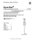
Instructions, Repair and Parts Dyna-Star® HP Pump System 332540E EN Provides lubricant flow and pressure to operate a single line parallel automatic lubrication system. For automatic lubrication systems only. Not approved for use in European explosive atmosphere locations. Important Safety Instructions Read all warnings and instructions in this manual and the Dyna-Star HP and HF Pump instruction manual. Save all instructions. Maximum Working Pressure: 3500 psi (24.1 MPa, 241 bar) Models: All models include Tube-in-Tube design, vent valve, cover and tank. System Models 77X100 Size Dip Low Follower Auto-Fill 35/60 90/120 Stick Level Plate* Shut Off Pound Pound X X 77X101 77X102 X X 77X103 77X104 77X105 X X X X X X X X X X *Can only be used with Low Level models. Models 77X100 and 77X101 shown Warnings Warnings The following warnings are for the setup, use, grounding, maintenance, and repair of this equipment. The exclamation point symbol alerts you to a general warning and the hazard symbols refer to procedure-specific risks. When these symbols appear in the body of this manual or on warning labels, refer back to these Warnings. Product-specific hazard symbols and warnings not covered in this section may appear throughout the body of this manual where applicable. WARNING WARNING FIRE AND EXPLOSION HAZARD When flammable fluids are present in the work area, such as gasoline and windshield wiper fluid, be aware that flammable fumes can ignite or explode. To help prevent fire and explosion: • Use equipment only in well ventilated area. • Eliminate all ignition sources, such as cigarettes and portable electric lamps. • Keep work area free of debris, including rags and spilled or open containers of solvent and gasoline. • Do not plug or unplug power cords or turn lights on or off when flammable fumes are present. • Ground all equipment in the work area. • Use only grounded hoses. • Stop operation immediately if static sparking occurs or you feel a shock. Do not use equipment until you identify and correct the problem. • Keep a working fire extinguisher in the work area. SKIN INJECTION HAZARD High-pressure fluid from dispensing device, hose leaks, or ruptured components will pierce skin. This may look like just a cut, but it is a serious injury that can result in amputation. Get immediate surgical treatment. • Do not point dispensing device at anyone or at any part of the body. + • Do not put your hand over the fluid outlet. • Do not stop or deflect leaks with your hand, body, glove, or rag. • Follow the Pressure Relief Procedure when you stop dispensing and before cleaning, checking, or servicing equipment. • Tighten all fluid connections before operating the equipment. • Check hoses and couplings daily. Replace worn or damaged parts immediately. 2 332540E Warnings WARNING WARNING PRESSURIZED EQUIPMENT HAZARD Over-pressurization can result in equipment rupture and serious injury. • A pressure relief valve is required at each pump outlet. • Follow Pressure Relief Procedure in this manual before servicing. EQUIPMENT MISUSE HAZARD Misuse can cause death or serious injury. • Do not operate the unit when fatigued or under the influence of drugs or alcohol. • Do not exceed the maximum working pressure or temperature rating of the lowest rated system component. See Technical Data in all equipment manuals. • Use fluids and solvents that are compatible with equipment wetted parts. See Technical Data in all equipment manuals. Read fluid and solvent manufacturer’s warnings. For complete information about your material, request MSDS from distributor or retailer. • Turn off all equipment and follow the Pressure Relief Procedure when equipment is not in use. • Check equipment daily. Repair or replace worn or damaged parts immediately with genuine manufacturer’s replacement parts only. • Do not alter or modify equipment. Alterations or modifications may void agency approvals and create safety hazards. • Make sure all equipment is rated and approved for the environment in which you are using it. • Use equipment only for its intended purpose. Call your distributor for information. • Route hoses and cables away from traffic areas, sharp edges, moving parts, and hot surfaces. • Do not kink or over bend hoses or use hoses to pull equipment. • Keep children and animals away from work area. • Comply with all applicable safety regulations. MOVING PARTS HAZARD Moving parts can pinch, cut or amputate fingers and other body parts. • Keep clear of moving parts. • Do not operate equipment with protective guards or covers removed. • Pressurized equipment can start without warning. Before checking, moving, or servicing equipment, follow the Pressure Relief Procedure and disconnect all power sources. 332540E 3 Warnings WARNING WARNING BURN HAZARD Equipment surfaces and fluid that’s heated can become very hot during operation. To avoid severe burns: • Do not touch hot fluid or equipment. PERSONAL PROTECTIVE EQUIPMENT Wear appropriate protective equipment when in the work area to help prevent serious injury, including eye injury, hearing loss, inhalation of toxic fumes, and burns. This protective equipment includes but is not limited to: • Protective eyewear, and hearing protection. • Respirators, protective clothing, and gloves as recommended by the fluid and solvent manufacturers. 4 332540E Typical Installation: Injector System Typical Installation: Injector System The installation shown in below is only a guide for selecting and installing system components. Contact your Graco distributor for assistance in planning a system to suit your needs. F Controller Capabilities Low Reservoir Level Switch (Level Indicator, optional) D C Pressure Switch for System Control E Remote Alarm Device (Light or Horn) (user provided Pump Power P Motor Control Board Pump Signal B L Vent Valve S M R J A H K K G N Back Front FIG. 1 Key: A B C D E F G H J K L Lubricant outlet connection Pump Ignition switch* High-pressure lubricant supply lines* Injector banks* Lubrication controller* Fill port (not used with Auto-Fill Shut Off) Overflow port (not used with Auto-Fill Shut Off) Breather Reservoir Vent Valve 332540E M N P R S Motor Fluid overflow container Pump - remote filling station Reservoir - remote filling station Auto-Fill Shut Off *User provided 5 Typical Installation: Series Progressive System Typical Installation: Series Progressive System The installation shown below is only a guide for selecting and installing system components. Contact your Graco distributor for assistance in planning a system to suit your needs. F Controller Capabilities Low Reservoir Level Switch (Level Indicator, optional) C Pressure Switch for System Control N Remote Alarm Device (Light or Horn) (user provided N Pump Power D B Motor Control Board Pump Signal J L M A N H E K K L G N Back Front FIG. 2 Key: A B C D E F G H J K L M N Lubricant output connection† Pump† Ignition switch* High-pressure lubricant supply lines* Primary metering device* Lubrication controller* Fill port (for reference only; non-tube-in-tube models only) Overflow port (for reference only) Breather (for reference only) Reservoir / Tank (for reference only) Secondary metering device Motor Bearing † The pump outlet requires modification to convert an Injector-based system to Series Progressive system. Dyna-Star HF and HP Outlet Adapter Kits 77X543 rated 4000 psi (275.8 bar, 27.58 MPa) and 77X544 rated 5000 psi (344.7 bar, 34.47 MPa) are available from Graco. Contact Graco Customer Service or your local Graco distributor to identify the correct kit for your installation location. *User provided 6 332540E Installation Installation Pressure Relief Follow the Pressure Relief Procedure whenever you see this symbol. This equipment stays pressurized until pressure is manually relieved. To help prevent serious injury from pressurized fluid, such as skin injection, splashing fluid and moving parts, follow the Pressure Relief Procedure when you stop dispensing and before cleaning, checking, or servicing the equipment. To relieve pressure in the system, use two wrenches working in opposite directions on pump outlet fitting to slowly loosen fitting only until fitting is loose and no more lubricant or air is leaking from fitting as shown in FIG. 3. COMPONENT RUPTURE HAZARD The maximum working pressure of each component in the system may not be the same. To reduce the risk of overpressurizing any component in the system, be sure you know the maximum working pressure of each component. Never exceed the maximum working pressure of the lowest rated component in the system. Overpressurizing any component can result in rupture, fire, explosion, property damage and serious injury. • Read and follow instructions supplied with each system component. • Reference letters used in the following Installation instructions, refer to Typical Installation Key, page 5. Wiring Grounding The equipment must be bonded (grounded) directly to the truck. Grounding reduces the risk of static shock due to static build up on the equipment. System Configuration and Wiring FIG. 3 NOTE: Cable wiring harness kits are available from Graco. See Parts page 11 for a complete list of available kits. Fuses NOTICE Fuses (user supplied) are required on all models. To avoid equipment damage: 332540E • Never operate the Dyna-Star Pump models without a fuse installed. • A fuse of the correct voltage and amperage must be installed in line with the power entry to the system. Graco recommends using 35A fuses. 7 Operation Reservoir Installation HEAVY EQUIPMENT HAZARD Equipment is heavy. To avoid injury: • Be sure unit is securely mounted before operation. • Do not lift pressurized equipment. • Lifting or moving heavy equipment incorrectly can cause serious injury. To avoid serious injuries, such as muscle strain or back injuries, when moving pump always use a lifting aid secured to the pump lift ring. See Technical Data, in the pump instruction manual for pump weight. 1. Mount Reservoir on sturdy, flat surface. Note location of Fill Port (G) and Lubricant Outlet Connection (A) for easy access once installed. 2. Connect High Pressure Lubricant Supply Line (D) to the Lubricant Outlet Connection (A). Operation • Read and follow instructions supplied with each system component. • Reference letters used in the following Installation instructions, refer to Typical Installation Key, page 5. Start-up Do not insert finger into the overflow port while filling a reservoir equipped with a follow plate. Injury or amputation could result. Priming 1. After reservoir/tank is completely filled, remove high pressure lubricant supply line (D) from the outlet. 3. Ground system (see Grounding). Mount reservoir to grounded chassis member. 2. Connect power to pump. Pump Installation 3. Start pump and run pump until all air has been expelled and fluid flow is continuous. Pump installation instructions are provided in the Dyna-Star HP or HF Pump instruction manual 332514 provided with your system. 4. Reconnect the high pressure lubricant supply line (D) to outlet. Vent Valve Kit The vent valve is used to reduce system pressure and allow the injector to reset. When energized, grease is pumped out through the outlet port (marked 0) on the vent valve. When de-energized, it vents pressure internally to tank. Refer to the Dyna-Star HP or HF Vent Valve Kit manual 332515 for installation and operation instructions. Auto-Fill Shut Off The Auto-Fill Shut Off is used refilling the grease tank/reservoir instead of the fill port (G). When the grease level in the tank is full, the Auto-Fill Shut Off automatically ends the filling operation. Refer to the Auto-Fill Shut Off Kit instruction manual 332518 for complete instructions and additional information. 8 332540E Operation Filling Reservoir There are two reservoir filling options; Fill Port (G) or Auto-Fill Shut Off (S). Only one method of filling can be used. Filling Reservoir With Fill Port (G) NOTICE To prevent damage to the unit: Filling Reservoir With Auto-Fill Shut Off (S) Refer to Auto-Fill Shut Off Kit instruction manual 332518. Shutdown For normal system shut down, disconnect power by turning off the ignition switch (C). • Check Breather vent (J) for proper operation before filling reservoir. • Open Overflow Port (H) before filling for visual inspection of lubricant level. • Do not fill beyond Overflow Port (H). • Do not use Overflow Port (H) to fill reservoir. 1. Connect lubricant supply hose from remote filling station pump to Fill Port (G). 2. Remove plug from Overflow Port (H). 3. Slowly turn on supply lubricant until level of lubricant reaches Overflow Port (H). NOTE: For systems with a follower plate, fill unit until the follower plate reaches the Overflow Port (H). 4. Disconnect lubricants supply hose from Fill Port (G). 5. Plug Fill Port (G) and Overflow Port (H). NOTICE Never allow pump to run dry of the fluid being pumped. Running a pump dry can damage the pump. 332540E 9 Parts List Parts List Model 77X100: Dyna-Star Pump, 60#, Dip Stick, Reservoir, Cover, Vent Valve Model 77X101: Dyna-Star Pump, 90#, Dip Stick, Reservoir, Cover, Vent Valve Ref. No. 1 1a 1b 3 3a 3c 3d 3e 3f 3g 3h 3j 3k 3l 3m 3n 4 8 9 10 Part No. Description 77X011 KIT, pump and vent valve, includes 1a and 1b, Dyna-Star 60#, models 77X100, see instruction manual 332514 77X012 KIT, pump and vent valve, includes 1a and 1b, Dyna-Star 90#, models 77X101, see instruction manual 332514 PUMP VENT VALVE, see instruction manual 332519 77X535 KIT, reservoir, 60# grease, includes 3a-3n, models 77X100 77X536 KIT, reservoir, 90# grease, includes 3a-3n models 77X101 . PLUG, pipe . NUT, flanged, hex . SCREW, cap, flange head . BREATHER 194868 . GASKET, cover . PAIL, reservoir, 60#, included in kit 77X535 . PAIL, reservoir, 90#, included in kit 77X536 16V394 . COVER, reservoir 109114 . SCREW, cap 15M442 . GASKET, pump 104572 . WASHER, lock, spring 16V396 . SEAL 16V395 . COVER 77X531 KIT, dip stick, 60#, grease, see instruction manual 332515 77X530 KIT, dip stick, 90#, grease, see instruction manual 332515 195341 16U728 15H108 3j Qty 1 LABEL, notice, breather LABEL, over pressurize warning LABEL, pinch warning 3l 10 1a 9 1b 1 4 3d 1 1 3k 1 3n 3e 3m 1 3d 2 8 8 1 1 3h 3c 8 1 1 4 1 4 1 1 1 3a 3f 3c 3g 1 1 1 1 3a Replacement Danger and Warning labels, tags and cards are available at no cost. 10 332540E Parts List Parts List Model 77X102: Dyna-Star Pump, 60#, Auto-Fill Shut Off, Reservoir, Cover, Vent Valve Model 77X103: Dyna-Star Pump, 90#, Auto-Fill Shut Off, Reservoir, Cover, Vent Valve Ref. No. 1 Part No. Description 77X011 77X012 1a 1b 3 77X535 77X536 3a 3c 3d 3e 3f 3g 3h 3i 3j 3k 3l 5 5a 5b 5c 5d 5e 5f 8 9 10 194868 16V394 104663 109114 15M442 104572 77X521 195341 16U728 16U727 KIT, pump and vent valve, includes 1a and 1b, Dyna-Star 60#, models 77X100, see instruction manual 332514 KIT, pump and vent valve, includes 1a and 1b, Dyna-Star 90#, models 77X101, see instruction manual 332514 PUMP VENT VALVE, see instruction manual 332519 KIT, reservoir, 60# grease, includes 3a-3l, models 77X100 KIT, reservoir, 90# grease, includes 3a-3l, models 77X101 . PLUG, pipe . NUT, flanged, hex . SCREW, cap, flange head . BREATHER . GASKET, cover . PAIL, reservoir, 60#, included in kit 77X535 . PAIL, reservoir, 90#, included in kit 77X536 . COVER, reservoir . PLUG, pipe . SCREW, cap . GASKET, pump . WASHER, lock, spring VALVE, auto-fill shut off, see instruction manual 332518 VALVE, auto shut off DIAPHRAGM, assembly TUBE, vent valve FITTING, connector, 3/8 in. npt* x JIC BOLT, M8 x 1.25 x 2 mm SEAL, auto shutoff valve LABEL, notice, breather LABEL, over pressurize warning LABEL, pinch warning Replacement Danger and Warning labels, tags and cards are available at no cost. 332540E 3j Qty 1 9 1a 3l 10 1 1b 5a 5d 1 1 1 9 5f 5c 3e 3i 3d 8 1 3h 2 6 6 1 1 1 3k 5e 3f 5b 1 1 1 4 1 4 1 1 1 1 2 2 1 1 1 1 3a 3c 3g 3a 11 Parts List Parts List Ref. No. Part No. Description 1 77X011 77X012 1a 1b 3 77X535 77X536 3a 3c 3d 3e 3f 3g 100737 194868 3h 3j 3k 3l 3m 3n 6 16V394 109114 15M442 104572 16V396 16V395 77X522 7 8 9 10 77X500 195341 16U728 15H108 Qty KIT, pump and vent valve, includes 1a and 1b, Dyna-Star 60#, models 77X100, see instruction manual 332514 KIT, pump and vent valve, includes 1a and 1b, Dyna-Star 90#, models 77X101, see instruction manual 332514 PUMP VENT VALVE, see instruction manual 332519 KIT, reservoir, 60# grease, includes 3a-3n, models 77X100 KIT, reservoir, 90# grease, includes 3a-3n, models 77X101 . PLUG, pipe . NUT, flanged, hex . SCREW, cap, flange head . BREATHER . GASKET, cover . PAIL, reservoir, 60#, included in kit 77X535 . PAIL, reservoir, 90#, included in kit 77X536 . COVER, reservoir . SCREW, cap . GASKET, pump . WASHER, lock, spring . SEAL . COVER KIT, low level, see instruction manual 332515 KIT, plate, follower 60# / 90# LABEL, notice, breather LABEL, over pressurize warning LABEL, pinch warning 6 3j 3l 1a 1 10 9 1b 1 3d 1 1 3n 1 3e 3m 3d 1 3h 3k 2 8 8 1 1 1 3c 8 3f 1 1 4 1 4 1 1 1 1 1 1 1 3c 7 3a 3g Replacement Danger and Warning labels, tags and cards are available at no cost. Cable Harness Kits (all models) Part No. Description 77X527 77X528 77X529 24N402 12 3a KIT, cable, power series progressive system only. Used with 77X528 KIT, cable, power extension, 15 ft (4.6 m). Used with 77X527 and 77X529 KIT, cable, power injector system only. For use with 77X528 KIT, cable, 6 ft (1.8 m), vent valve, 2 pin. For use with vent valve control. 332540E Technical Data Technical Data Maximum working pressure Pump wetted parts Vent valve wetted parts Reservoir wetted parts Reservoir overflow port size Reservoir fill port size Lubricant outlet port size Grease capacity Model 77X101, 77X103, 77X105 Model 77X100, 77X102, 77X104 Sound Data: All pumps 332540E 3500 psi (24.1 MPa, 241 bar See Dyna-Star HP and HF Pump manual: 332514 See Dyna-Star HP and HF Vent Valve Kit manual: 332519 steel, buna-n rubber 1/2 inch npt 1/2 inch npt 3/8 npt (f) 90 lb. (41 kg) 60 lb. (27 kg) See Dyna-Star HP and HF Pump manual: 332514 13 Dimensions Dimensions D E A F G B C 60 lb Models Ref US (inch) Metric (cm) US (inch) Metric (cm) A B C D E F 30.5 14.5 77.47 36.83 38.0 14.5 96.52 36.83 G 14 90 lb Models 1/2 inch npt 1/2 inch-14 npt 14.5 36.83 19.4 49.28 1/2 inch npt 1/2 inch-14 npt 14.5 36.83 27.0 36.83 7/16 inch Ø hole - 6; 13-7/8 inch bolt circle 332540E Notes Notes 332540E 15 Graco Standard Warranty Graco warrants all equipment referenced in this document which is manufactured by Graco and bearing its name to be free from defects in material and workmanship on the date of sale to the original purchaser for use. With the exception of any special, extended, or limited warranty published by Graco, Graco will, for a period of twelve months from the date of sale, repair or replace any part of the equipment determined by Graco to be defective. This warranty applies only when the equipment is installed, operated and maintained in accordance with Graco’s written recommendations. This warranty does not cover, and Graco shall not be liable for general wear and tear, or any malfunction, damage or wear caused by faulty installation, misapplication, abrasion, corrosion, inadequate or improper maintenance, negligence, accident, tampering, or substitution of non-Graco component parts. Nor shall Graco be liable for malfunction, damage or wear caused by the incompatibility of Graco equipment with structures, accessories, equipment or materials not supplied by Graco, or the improper design, manufacture, installation, operation or maintenance of structures, accessories, equipment or materials not supplied by Graco. This warranty is conditioned upon the prepaid return of the equipment claimed to be defective to an authorized Graco distributor for verification of the claimed defect. If the claimed defect is verified, Graco will repair or replace free of charge any defective parts. The equipment will be returned to the original purchaser transportation prepaid. If inspection of the equipment does not disclose any defect in material or workmanship, repairs will be made at a reasonable charge, which charges may include the costs of parts, labor, and transportation. THIS WARRANTY IS EXCLUSIVE, AND IS IN LIEU OF ANY OTHER WARRANTIES, EXPRESS OR IMPLIED, INCLUDING BUT NOT LIMITED TO WARRANTY OF MERCHANTABILITY OR WARRANTY OF FITNESS FOR A PARTICULAR PURPOSE. Graco’s sole obligation and buyer’s sole remedy for any breach of warranty shall be as set forth above. The buyer agrees that no other remedy (including, but not limited to, incidental or consequential damages for lost profits, lost sales, injury to person or property, or any other incidental or consequential loss) shall be available. Any action for breach of warranty must be brought within two (2) years of the date of sale. GRACO MAKES NO WARRANTY, AND DISCLAIMS ALL IMPLIED WARRANTIES OF MERCHANTABILITY AND FITNESS FOR A PARTICULAR PURPOSE, IN CONNECTION WITH ACCESSORIES, EQUIPMENT, MATERIALS OR COMPONENTS SOLD BUT NOT MANUFACTURED BY GRACO. These items sold, but not manufactured by Graco (such as electric motors, switches, hose, etc.), are subject to the warranty, if any, of their manufacturer. Graco will provide purchaser with reasonable assistance in making any claim for breach of these warranties. In no event will Graco be liable for indirect, incidental, special or consequential damages resulting from Graco supplying equipment hereunder, or the furnishing, performance, or use of any products or other goods sold hereto, whether due to a breach of contract, breach of warranty, the negligence of Graco, or otherwise. FOR GRACO CANADA CUSTOMERS The Parties acknowledge that they have required that the present document, as well as all documents, notices and legal proceedings entered into, given or instituted pursuant hereto or relating directly or indirectly hereto, be drawn up in English. Les parties reconnaissent avoir convenu que la rédaction du présente document sera en Anglais, ainsi que tous documents, avis et procédures judiciaires exécutés, donnés ou intentés, à la suite de ou en rapport, directement ou indirectement, avec les procédures concernées. Graco Information To place an order, contact your Graco distributor or to identify the nearest distributor call, Toll Free: 1-800-533-9655, Fax: 612-378-3590 All written and visual data contained in this document reflects the latest product information available at the time of publication. Graco reserves the right to make changes at any time without notice. For patent information, see www.graco.com/patents. Original instructions. This manual contains English. MM 332540 Graco Headquarters: Minneapolis International Offices: Belgium, China, Japan, Korea GRACO INC. AND SUBSIDIARIES • P.O. BOX 1441 • MINNEAPOLIS MN 55440-1441 • USA Copyright 2013, Graco Inc. All Graco manufacturing locations are registered to ISO 9001. www.graco.com June 2014