1
Installation
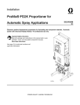
ProMix® PD2K Electronic
Proportioner
332457C
EN
Electronic positive displacement proportioner for fast-setting two-component materials. Manual system
with Advanced Display Module. For professional use only.
Important Safety Instructions
Read all warnings and instructions in this manual. Save these
instructions.
See page 3 for model part numbers
and approvals information.
PROVEN QUALITY. LEADING TECHNOLOGY.
Contents
Warnings ........................................................... 5
Fluid Supply ....................................................... 22
Fluid Requirements ...................................... 22
Single Color Connections ............................. 23
Color Change Connections........................... 23
Important Isocyanate (ISO) Information ................ 8
TSL Cup Kit........................................................ 24
System Control Drawing 16P577 ......................... 10
Solvent Meter Accessory..................................... 25
Configuring Your System .................................... 12
1. Select a Base Model ................................ 12
2. Select Hoses ........................................... 14
3. Select Mix Manifold .................................. 16
4. Select a Spray Gun .................................. 16
5. Select Color and Catalyst Change
Kits ................................................ 17
6. Select Pump Expansion Kits ..................... 17
Light Tower Accessory........................................ 25
Related Manuals ................................................ 2
Models............................................................... 3
General Information ............................................ 18
Electrostatic Air Hose Quick Disconnect Kit
24S004................................................. 25
Electrical Supply ................................................. 26
Electrical Requirements................................ 26
Electrical Connections .................................. 26
Grounding .......................................................... 27
Location ............................................................. 18
Electrical Schematics .......................................... 31
Optional Cables and Modules ....................... 37
Install the Display Module.................................... 19
Dimensions ........................................................ 38
Install the Booth Control ...................................... 20
Technical Data ................................................... 39
Air Supply .......................................................... 21
Graco Standard Warranty.................................... 40
Related Manuals
Manual No.
Description
Manual No.
Description
3A2800
PD2K Proportioner Repair-Parts
Manual, Manual Systems
332454
Color Change Valve Repair-Parts
Manual
332562
PD2K Proportioner Operation
Manual, Manual Systems
332455
Color Change Kits InstructionsParts Manual
3A2801
Mix Manifold Instructions-Parts
Manual
332456
3rd and 4th Pump Kits
Instructions-Parts Manual
332339
Pump Repair-Parts Manual
2
332457C
Models
Models
See Figs. 1–7 for component identification labels, including approval information and certification.
Part No.
Series
Maximum Air Working
Pressure
Maximum Fluid Working
Pressure
MC1000
A
100 psi (0.7 MPa,
7.0 bar)
300 psi (2.068 MPa, 20.68 bar)
MC2000
A
100 psi (0.7 MPa,
7.0 bar)
1500 psi (10.34 MPa,
103.4 bar)
0359
Location of PD2K and
Electrical Control Box
(ECB) Labels
II 2 G
Figure 1 Model MC1000 (Low Pressure) Identification
Label
Figure 2 24M672 Control Box Identification Label
332457C
Continued on the next page.
3
Models
Figure 3 Model MC2000 (High Pressure)
Identification Label
Figure 4 Non-Intrinsically Safe Color Change Control (Accessory) Identification Label
Figure 5 Intrinsically Safe Color Change Control
(Accessory) Identification Label
Figure 6 Booth Control Identification Label
Figure 7 Pump Expansion Kit (Accessory) Identification Label
4
332457C
Warnings
Warnings
The following warnings are for the setup, use, grounding, maintenance and repair of this equipment. The
exclamation point symbol alerts you to a general warning and the hazard symbol refers to procedure-specific
risks. When these symbols appear in the body of this manual or on warning labels, refer back to these
Warnings. Product-specific hazard symbols and warnings not covered in this section may appear throughout
the body of this manual where applicable.
WARNING
FIRE AND EXPLOSION HAZARD
Flammable fumes, such as solvent and paint fumes, in work area can ignite or explode. To help
prevent fire and explosion:
• Use equipment only in well ventilated area.
• Eliminate all ignition sources; such as pilot lights, cigarettes, portable electric lamps, and
plastic drop cloths (potential static arc).
• Keep work area free of debris, including solvent, rags and gasoline.
• Do not plug or unplug power cords, or turn power or light switches on or off when flammable
fumes are present.
• Ground all equipment in the work area. See Grounding instructions.
• Use only grounded hoses.
• Hold gun firmly to side of grounded pail when triggering into pail. Do not use pail liners unless
they are antistatic or conductive.
• Stop operation immediately if static sparking occurs or you feel a shock, Do not use
equipment until you identify and correct the problem.
• Keep a working fire extinguisher in the work area.
ELECTRIC SHOCK HAZARD
This equipment must be grounded. Improper grounding, setup, or usage of the system can
cause electric shock.
• Turn off and disconnect power at main switch before disconnecting any cables and before
servicing or installing equipment.
• Connect only to grounded power source.
• All electrical wiring must be done by a qualified electrician and comply with all local codes
and regulations.
332457C
5
Warnings
INTRINSIC SAFETY
WARNING
Intrinsically safe equipment that is installed improperly or connected to non-intrinsically safe
equipment will create a hazardous condition and can cause fire, explosion, or electric shock.
Follow local regulations and the following safety requirements.
• Be sure your installation complies with national, state, and local codes for the installation of
electrical apparatus in a Class I, Group D, Division 1 (North America) or Class I, Zones 1
and 2 (Europe) Hazardous Location, including all of the local safety fire codes (for example,
NFPA 33, NEC 500 and 516, OSHA 1910.107, etc.).
• To help prevent fire and explosion:
• Do not install equipment approved only for a non-hazardous location in a hazardous
location. See model ID label for the intrinsic safety rating of your model.
• Do not substitute system components as this may impair intrinsic safety.
• Equipment that comes in contact with the intrinsically safe terminals must be rated for Intrinsic
Safety. This includes DC voltage meters, ohmmeters, cables, and connections. Remove the
unit from the hazardous area when troubleshooting.
SKIN INJECTION HAZARD
High-pressure fluid from gun, hose leaks, or ruptured components will pierce skin. This may
look like just a cut, but it is a serious injury that can result in amputation. Get immediate surgical
treatment.
•
•
•
•
•
•
Do not spray without tip guard and trigger guard installed.
Engage trigger lock when not spraying.
Do not point gun at anyone or at any part of the body.
Do not put your hand over the spray tip.
Do not stop or deflect leaks with your hand, body, glove, or rag.
Follow the Pressure Relief Procedure when you stop spraying/dispensing and before
cleaning, checking, or servicing equipment.
• Tighten all fluid connections before operating the equipment.
• Check hoses and couplings daily. Replace worn or damaged parts immediately.
MOVING PARTS HAZARD
Moving parts can pinch, cut or amputate fingers and other body parts.
• Keep clear of moving parts.
• Do not operate equipment with protective guards or covers removed.
• Pressurized equipment can start without warning. Before checking, moving, or servicing
equipment, follow the Pressure Relief Procedure and disconnect all power sources.
TOXIC FLUID OR FUMES
Toxic fluids or fumes can cause serious injury or death if splashed in the eyes or on skin,
inhaled, or swallowed.
• Read MSDSs to know the specific hazards of the fluids you are using.
• Store hazardous fluid in approved containers, and dispose of it according to applicable
guidelines.
• Always wear chemically impermeable gloves when spraying, dispensing, or cleaning
equipment.
6
332457C
Warnings
WARNING
PERSONAL PROTECTIVE EQUIPMENT
Wear appropriate protective equipment when in the work area to help prevent serious injury,
including eye injury, hearing loss, inhalation of toxic fumes, and burns. This protective
equipment includes but is not limited to:
• Protective eyewear, and hearing protection.
• Respirators, protective clothing, and gloves as recommended by the fluid and solvent
manufacturer.
EQUIPMENT MISUSE HAZARD
Misuse can cause death or serious injury.
• Do not operate the unit when fatigued or under the influence of drugs or alcohol.
• Do not exceed the maximum working pressure or temperature rating of the lowest rated
system component. See Technical Data in all equipment manuals.
• Use fluids and solvents that are compatible with equipment wetted parts. See Technical Data
in all equipment manuals. Read fluid and solvent manufacturer’s warnings. For complete
information about your material, request MSDS from distributor or retailer.
• Do not leave the work area while equipment is energized or under pressure.
• Turn off all equipment and follow the Pressure Relief Procedure when equipment is not in use.
• Check equipment daily. Repair or replace worn or damaged parts immediately with genuine
manufacturer’s replacement parts only.
• Do not alter or modify equipment. Alterations or modifications may void agency approvals
and create safety hazards.
• Make sure all equipment is rated and approved for the environment in which you are using it.
• Use equipment only for its intended purpose. Call your distributor for information.
• Route hoses and cables away from traffic areas, sharp edges, moving parts, and hot surfaces.
• Do not kink or over bend hoses or use hoses to pull equipment.
• Keep children and animals away from work area.
• Comply with all applicable safety regulations.
332457C
7
Important Isocyanate (ISO) Information
Important Isocyanate (ISO) Information
Isocyanates (ISO) are catalysts used in two
component materials.
Keep Components A and B Separate
Isocyanate Conditions
Cross-contamination can result in cured
material in fluid lines which could cause serious
injury or damage equipment. To prevent
cross-contamination:
Spraying or dispensing materials containing
isocyanates creates potentially harmful mists,
vapors, and atomized particulates.
Read material manufacturer’s warnings and
material MSDS to know specific hazards and
precautions related to isocyanates.
Prevent inhalation of isocyanate mists, vapors,
and atomized particulates by providing sufficient
ventilation in the work area. If sufficient ventilation
is not available, a supplied-air respirator is required
for everyone in the work area.
To prevent contact with isocyanates, appropriate
personal protective equipment, including
chemically impermeable gloves, boots, aprons,
and goggles, is also required for everyone in the
work area.
Material Self-ignition
Some materials may become self-igniting if applied
too thick. Read material manufacturer’s warnings
and material MSDS.
• Never interchange component A and component
B wetted parts.
• Never use solvent on one side if it has been
contaminated from the other side.
Moisture Sensitivity of Isocyanates
Exposure to moisture (such as humidity) will cause
ISO to partially cure; forming small, hard, abrasive
crystals, which become suspended in the fluid.
Eventually a film will form on the surface and the ISO
will begin to gel, increasing in viscosity.
NOTICE
Partially cured ISO will reduce performance and
the life of all wetted parts.
• Always use a sealed container with a desiccant
dryer in the vent, or a nitrogen atmosphere.
Never store ISO in an open container.
• Keep the ISO pump wet cup or reservoir (if
installed) filled with appropriate lubricant. The
lubricant creates a barrier between the ISO and
the atmosphere.
• Use only moisture-proof hoses compatible with
ISO.
• Never use reclaimed solvents, which may
contain moisture. Always keep solvent
containers closed when not in use.
• Always lubricate threaded parts with an
appropriate lubricant when reassembling.
NOTE: The amount of film formation and rate of
crystallization varies depending on the blend of ISO,
the humidity, and the temperature.
8
332457C
Important Isocyanate (ISO) Information
Changing Materials
NOTICE
Changing the material types used in your
equipment requires special attention to avoid
equipment damage and downtime.
• When changing materials, flush the equipment
multiple times to ensure it is thoroughly clean.
• Always clean the fluid inlet strainers after
flushing.
• Check with your material manufacturer for
chemical compatibility.
• When changing between epoxies and urethanes
or polyureas, disassemble and clean all fluid
components and change hoses. Epoxies often
have amines on the B (hardener) side. Polyureas
often have amines on the A (resin) side.
332457C
9
System Control Drawing 16P577
System Control Drawing 16P577
Do not substitute or modify system components
as this may impair intrinsic safety. For installation,
maintenance, or operation instructions, read
instruction manuals. Do not install equipment
approved only for non-hazardous location in a
hazardous location. See the identification label for
the intrinsic safety rating for your model.
NOTES FOR SYSTEM CONTROL DRAWING 16P577 (FM13ATEX0026 SYSTEM ASSEMBLY
CERTIFICATE)
Alternate M12 CAN Cables, for Hazardous Locations
Cable Part No.
Length ft (m)
16V423
2.0 (0.6)
16V424
3.0 (1.0)
16V425
6.0 (2.0)
16V426
10.0 (3.0)
16V427
15.0 (5.0)
16V428
25.0 (8.0)
16V429
50.0 (16.0)
16V430
100.0 (32.0)
2. The non-intrinsically safe terminals (power rail) must not be connected to any device which uses or
generates more than Um = 250 Vrms or dc unless it has been determined that the voltage has been
adequately isolated.
3. The electrical enclosure ground screw must be connected to a true earth ground using the supplied
ground strap (223547) or by an equivalent 10 AWG or larger isolated conductor. Resistance from the
electrical enclosure ground to the true earth ground shall not exceed 1 ohm.
4. Multiple earthing of components is allowed. Intrinsically safe apparatus provides isolation from earth to
500 Vrms.
Do not operate system with power barrier cover removed.
6. Installation should be in accordance with ANSI/ISA RP12.06.01 “Installation of Intrinsically Safe Systems
for Hazardous (Classified) Locations” and the National Electrical Code® (ANSI/NFPA 70).
7. Installation in Canada should be in accordance with the Canadian Electrical Code, CAS C22.1, Part I,
Appendix F.
8. For ATEX, install per EN 60079–14 and applicable local and national codes.
9. For IECEx install per IEC 60079–14 and applicable local and national codes.
10
332457C
System Control Drawing 16P577
NON-HAZARDOUS LOCATION ONLY
HAZARDOUS (CLASSIFIED) LOCATION
Class 1, Div 1, Group D, T3 (USA and Canada)
Class 1, Zone 1, Group IIA, T3 (ATEX and IECEx)
Ta = 2°C to 50°C
NON-HAZARDOUS LOCATION ONLY
POWER IN
250 VAC MAXIMUM SUPPLY VOLTAGE
HAZARDOUS (CLASSIFED) LOCATION
CLASS 1, DIV 1, GROUP D, T3 (USA AND CANADA)
CLASS 1, ZONE 1, GROUP IIA, T3 (ATEX AND IECEx)
Ta = 2 C TO 50 C
PROMIX PD2K
ELECTRICAL ENCLOSURE
(24M672)
POWER
BARRIER
(248192)
CABLE
(16V426)
FM13ATEX0026
IECEx FMG 13.0011
ASSOCIATED APPARATUS
CABLE (16V429)
CABLE
(16V426)
COMMUNICATION J4
OR
BARRIER
(24M485)
J3
COLOR CHANGE MODULE
(24R219, 24R220, 24R221, 24R222)
FM13ATEX0026
IECEx FMG 13.0011
INTRINSIC SAFE APPARATUS
COLOR CHANGE MODULE
(24R219, 24R220, 24R221, 24R222)
FM13ATEX0026
IECEx FMG 13.0011
INTRINSIC SAFE APPARATUS
BOOTH CONTROL
(24M731)
FM13ATEX0026
IECEx FMG 13.0011
INTRINSIC SAFE APPARATUS
Figure 8 System Control Drawing 16P577
332457C
11
Configuring Your System
Configuring Your System
1. Select a Base Model
Choose a PD2K base model that meets your
application’s requirements. See Models, page 3 .
Base models include components A through F
shown in the Typical Installation Drawing. Base unit
components are described in the following table.
Component
Description
Fluid Pumps (A, B)
The base models include two fluid pumps, one for resin and one for
catalyst. Install in the non-hazardous area.
Solvent Valve (C)
Dispenses solvent to the gun during purge.
Booth Control (D)
The booth control enables the user to monitor and control the system.
Install the booth control in the hazardous location, near the painter.
Electrical Control Box (E)
The electrical control box includes a barrier board, intrinsically safe
isolation board, 24 Vdc and 48 Vdc power supplies, Enhanced Fluid
Control Module, and Pump Control Modules. It accepts 90–250 Vac line
power and converts that power to acceptable low voltage signals used
by other system components. Install the electrical control box in the
non-hazardous area.
Advanced Display Module (F)
The Advanced Display Module (ADM) enables the user to setup, monitor,
and control the system. Install the ADM in the non-hazardous area.
12
332457C
Configuring Your System
HAZARDOUS (CLASSIFIED) LOCATION
NON-HAZARDOUS LOCATION ONLY
Figure 9 Typical Installation
Component
Description
★ Components A through F are included with the base unit.
A★
Material A (Color) Pump
B★
Material B (Catalyst) Pump
C★
Solvent Valve
D★
Booth Control
E★
Electrical Control Box
F★
Advanced Display Module
Components G through K are included in optional color change kits.
G
Color Change Valves (accessory)
H
Color Change Module (accessory)
J
Catalyst Change Valves (accessory)
K
Catalyst Change Module (accessory)
Components L through S are accessories and must be ordered separately.
L
Fluid/Air Hose Bundle (accessory)
M
Mix Manifold (accessory)
N
Air Spray Gun (accessory)
P
Gun Air Hose (accessory)
R
Intrinsically Safe CAN Cable (to connect booth control to electrical control box)
S
Gun Fluid Hose (accessory)
332457C
13
Configuring Your System
2. Select Hoses
Hose Selection Tool
Use this chart to determine the proper size hose
bundle for your mix ratio and viscosity, then select a
hose bundle for your application from the tables on
the following page.
NOTE: Always use Graco hoses.
NOTE: Shaded areas may use hose sizes from either
of the two adjacent areas.
LOW PRESSURE SYSTEM, 0–300 psi (0–2.1 MPa, 0–21 bar)
Recommended Hose Sizes (internal diameter) for A and B
20 - 50
18
3/8ʺ A
1/8ʺ B
16
14
3/8ʺ A
1/4ʺ B
12
Mix
Ratio
(X:1)
10
8
1/4ʺ A
1/4ʺ B
6
4
2
0
10:1
Thick Resin (A)
1/4ʺ A
3/8ʺ B
7.5:1
5:1
2.5:1
1:1
1:2.5
Equal Viscosities
1:5
1:7.5
1:10
Thin Resin (A)
Thick Catalyst (B)
Thin Catalyst (B)
Viscosity Ratio (Resin [A] : Catalyst [B]
14
332457C
Configuring Your System
1/4 in. (6 mm) ID Hose Bundles
Select a hose bundle from the following table. Always use Graco hoses.
Application
Hose Bundle
Part No.
Length
Material
Low Pressure
Conventional Air
Spray
24T140
25 ft (7.6 m)
24T141
50 ft (15.2 m)
Nylon (A side and Solvent),
Moisture Guard (B side), Air Hose
24T138
25 ft (7.6 m)
24T139
50 ft (15.2 m)
24T247
25 ft (7.6 m)
24T248
50 ft (15.2 m)
24T245
25 ft (7.6 m)
24T246
50 ft (15.2 m)
Low Pressure
Electrostatic Air
Spray*
High Pressure
Conventional
Air-Assisted Spray
High Pressure
Electrostatic
Air-Assisted Spray*
Maximum
Fluid Working
Pressure
Nylon (A side and Solvent),
Moisture Guard (B side),
Grounded Air Hose with left-hand
thread
Nylon (A side and Solvent),
Moisture Guard (B side), Air Hose
Nylon (A side and Solvent),
Moisture Guard (B side),
Grounded Air Hose with left-hand
thread
225 psi (1.6
MPa, 16 bar)
225 psi (1.6
MPa, 16 bar)
2000 psi (13.8
MPa, 138 bar)
2000 psi (13.8
MPa, 138 bar)
* To use a quick disconnect on an existing electrostatic air hose, see
Electrostatic Air Hose Quick Disconnect Kit 24S004, page 25.
3/8 in. (10 mm) ID Fluid Hoses
If 3/8 in. (10 mm) fluid hose is required for your application, order one of the following to replace the 1/4 in.
hose in your hose bundle. Always use Graco hoses.
Application
Hose Part No.
Length
Material
Low Pressure Air
Spray
24T763
25 ft (7.6 m)
Nylon
24T764
50 ft (15.2 m)
Maximum Fluid Working Pressure
200 psi (1.4 MPa, 13.8 bar)
Fluid Whip Hoses
Select a fluid whip hose from the following table. Always use Graco hoses.
Application
Low Pressure
High Pressure
332457C
Hose Part No.
Hose I.D.
Length
Material
Maximum Fluid
Working Pressure
24N641
0.125 in. (3 mm)
6 ft (1.8 m)
Nylon
3200 psi (22 MPa,
220 bar)
24N305
0.25 in. (6 mm)
6 ft (1.8 m)
Nylon
225 psi (1.6 MPa,
16 bar)
24N641
0.125 in. (3 mm)
6 ft (1.8 m)
Nylon
3200 psi (22 MPa,
220 bar)
24N348
0.25 in. (6 mm)
6 ft (1.8 m)
PTFE
3000 psi (20.7 MPa,
207 bar)
15
Configuring Your System
3. Select Mix Manifold
The following mix manifold kits are available. The
mix manifolds attach to the painter’s belt, allowing
mixing to occur at the point of spray. See manual
3A2801 for further information.
Mix
Manifold
Description
Maximum Fluid
Working Pressure
24R99
1
Low pressure mix
manifold
300 psi (2.1 MPa,
21 bar)
24R99
2
High pressure mix
manifold
1500 psi (10.5
MPa, 105 bar)
24T273
High pressure
mix manifold, for
acid-compatible
materials
1500 psi (10.5
MPa, 105 bar)
4. Select a Spray Gun
Spray Guns
Select a spray gun from the following table.
Application
Gun Model
Gun Manual No.
Maximum Fluid Working
Pressure
Conventional Air Spray
AirPro
312414
300 psi (2.1 MPa, 21 bar)
Electrostatic Air Spray
Pro Xp
3A2494
100 psi (0.7 MPa, 7 bar)
Conventional
Air-Assisted Spray
G15
3A0149
1500 psi (10.5 MPa, 105
bar)
Electrostatic Air-Assisted
Spray
Pro Xp AA
3A2495
3000 psi (21 MPa, 210
bar)
16
332457C
Configuring Your System
5. Select Color and Catalyst Change Kits
Using the following table, choose color/catalyst change kits that meet your application’s requirements. The
kits include a manifold with valves and a control module. See color change kit manual 332455 for further
information.
Table 1 . Low Pressure Color/Catalyst Change Kits
(300 psi [2.068 MPa, 20.68 bar])
Kit Part No.
Kit Description
Table 2 . High Pressure Color/Catalyst Change Kits
(1500 psi [10.34 MPa, 103.4 bar])
Kit Part No.
Low Pressure Non-Circulating Kits
Kit Description
High Pressure Non-Circulating Kits
24R915
2 color or 2 catalyst
change valves
24R959
2 color or 2 catalyst
change valves
24R916
4 color or 4 catalyst
change valves
24R960
4 color or 4 catalyst
change valves
24R917
6 color change valves
24R961
6 color change valves
24R918
8 color change valves
24R962
8 color change valves
Low Pressure Circulating Kits
24R919
2 color or 2 catalyst
change valves
24R920
4 color or 4 catalyst
change valves
24R921
6 color change valves
24R922
8 color change valves
High Pressure Acid-Compatible NonCirculating Kits
24T579
2 catalyst change valves
24T580
4 catalyst change valves
High Pressure Circulating Kits
24R963
2 color or 2 catalyst
change valves
24R964
4 color or 4 catalyst
change valves
24R965
6 color change valves
24R966
8 color change valves
Kit Part No.
Kit Description
6. Select Pump Expansion Kits
The following table lists available kits to add a third
or fourth pump to your system. Each kit includes
one pump, a pump control module, solenoid, frame,
mounting bracket, and cabling. See pump expansion
kit manual 332456 for further information.
Low Pressure Pumps (300 psi [2.068
MPa, 20.68 bar])
24R968
Low pressure resin 70cc
pump
24R970
Low pressure catalyst
35cc pump
High Pressure Pumps (1500 psi [10.34
MPa, 103.4 bar])
332457C
24R969
High pressure resin
70cc pump
24R971
High pressure catalyst
35cc pump
17
General Information
General Information
Location
• Reference numbers and letters in parentheses
in the text refer to numbers and letters in the
illustrations.
• Be sure all accessories are adequately sized and
pressure-rated to meet system requirements.
• To protect the screens from paints and solvents,
clear-plastic protective shields (10 per pack) are
available. Order Part No. 197902 for the Advanced
Display Module and Part No. 15M483 for the
Booth Control. Clean the screens with a dry cloth if
necessary.
To prevent tipping which can cause serious injury
and equipment damage, the mounting stand
must be securely anchored to the floor or to an
appropriate base. The stand is not intended for
free-standing use or wall mounting.
Mounting the PD2K Base Unit:
• Mount the PD2K in a non-hazardous location.
• Ensure that the mounting surface and mounting
hardware are strong enough to support the weight
of the equipment, fluid, hoses, and stress caused
during operation.
• Do not mount to a wall.
• Secure the stand to the floor with 1/2 in. (13 mm)
bolts which engage at least 6 in. (152 mm) into
the floor to prevent the unit from tipping. See
Dimensions, page 38.
• There must be sufficient space on all sides of
the equipment for installation, operator access,
maintenance, and air circulation. The fans at the
back of the unit require a minimum of 6 in. (152
mm) clearance from the closest surface to ensure
adequate air circulation.
Mounting the Booth Control:
Install the booth control in a hazardous area at a
convenient location for the operator to view and
operate. See Install the Booth Control, page 20.
18
332457C
Install the Display Module
Install the Display Module
1. Use the screws (11) to mount the bracket (10) for
the Advanced Display Module (12) on the front of
the Control Box or on the wall, as you prefer.
2. Snap the Advanced Display Module into the
bracket.
Figure 11 Advanced Display Module Connection
Ports
Figure 10 Install Display Module
3. Connect one end of the 5 ft (1.5 m) CAN cable
(provided) to the Advanced Display Module
(M). The other end of the cable comes from the
factory connected to the Enhanced Fluid Control
Module (EFCM).
Item
Description
J
Battery Cover
K
Model Number
L
USB Drive Interface
M
CAN Cable Connection
N
ADM Status LEDs
P
Accessory Cable
Connection
R
Token Access Cover
NOTE: For a list of alternate cable lengths, see
Electrical Schematics, page 31. The total length of
all cable used in the system must not exceed 150
ft (45 m).
332457C
19
Install the Booth Control
Install the Booth Control
1. Use screws (S) to mount the bracket (10) for the
Booth Control (13) on the wall. Connect a ground
wire (G) to one of the screws. Connect the other
end of the ground wire to a true earth ground.
2. Snap the Booth Control into the bracket.
3. Connect the Booth Control to the Isolation Board
in the Electrical Control Box, using the 50 ft (15.2
m) intrinsically safe CAN cable (163).
NOTE: For a list of alternate cable lengths, see
Electrical Schematics, page 31. The total length
of cable used in the hazardous location must not
exceed 120 ft (36 m). The total length of all cable
used in the system must not exceed 150 ft (45 m).
Figure 12 Ground the Booth Control Bracket
Figure 13 Install the Booth Control
20
332457C
Air Supply
Air Supply
Air Requirements
switch detects air flow to the gun and signals the
controller when the gun is being triggered.
• Compressed air supply pressure: 85-100 psi
(0.6–0.7 MPa, 6.0-7.0 bar).
NOTE: If there is more than one gun (for
example, a separate gun for each color), the
atomizing air outlet (159c) must be branched to
each gun. For ease of maintenance, install a ball
valve at all air line tees.
• Air hoses: use grounded hoses that are correctly
sized for your system.
Trapped air can cause a pump or dispense
valve to cycle unexpectedly, which could result
in serious injury from splashing or moving parts.
Use bleed-type shutoff valves.
• Air regulator and bleed-type shutoff valve: include
in each air line to fluid supply equipment. Install
an additional shutoff valve upstream of all air line
accessories to isolate them for servicing.
To reduce the risk of fire and explosion if using
a Graco electrostatic gun, a shutoff valve must
be installed in the gun air line to shutoff the
atomizing and turbine air to the gun. Contact
your Graco distributor for information on air
shutoff valves for electrostatic applications.
Figure 14 Connect Atomizing Air
• Air line filter: to filter oil and water out of the air
supply and help avoid paint contamination and
clogged solenoids. See Technical Data, page 39 for
air filtration requirements.
Air Connections
1. Tighten all system air and fluid line connections
as they may have loosened during shipment.
2. Connect the main air supply line to the main air
inlet (136). This air line supplies the solenoids,
valves, and pumps. Do not use this line to supply
the gun’s atomizing air.
3. Connect a separate, dedicated, clean air supply
line to the air inlet (159a) of the air flow switch.
This air supplies gun atomizing air. The air flow
332457C
Figure 15 Air Manifold Connections
Key
Connection
Description
A
Air inlet
C
GFB/Air cutoff output
(plugged)
M
Exhaust muffler
S
Solvent cutoff output
21
Fluid Supply
Fluid Supply
Fluid Requirements
• Materials can be transferred from their original
containers or from a central paint recirculating line.
• Install a 100 mesh (minimum) fluid filter in the fluid
supply line, with a drain valve.
• To reduce the risk of equipment
overpressurization and rupture which can
cause injury, including skin injection, do not
exceed the pressure rating of the lowest rated
system component. See the identification
label for the maximum working pressure of the
equipment.
• To reduce the risk of injury, including skin
injection, you must install a shutoff valve
between each fluid supply line and the mix
manifold. Use the valves to shut off fluid during
maintenance and service.
Models are available to operate air spray (300 psi) or
air-assisted (1500 psi) systems with a capacity of up
to 800 cc/minute (depending on material viscosity).
NOTE: The fluid supply must be free of pressure
spikes, which are commonly caused by pump stroke
changeover. Read the supply pressure on the gauge
(P). Supply pressure must be as close as possible
to the pressure setpoint:
• For low pressure systems, ± 100 psi (0.7 MPa, 7
bar) of setpoint.
• For high pressure systems, ± 300 psi (2.1 MPa,
21 bar) of setpoint.
If necessary, install pressure regulators or a surge
tank on the pump fluid inlet lines to reduce pulsation.
Contact your Graco distributor for additional
information.
• Fluid supply pressure tanks, feed pumps, or
circulating systems can be used to supply fluid to
the system.
22
332457C
Fluid Supply
Single Color Connections
Color Change Connections
NOTE: Check valves (J, L) are provided on the inlet
and outlet manifolds of each pump.
If you are installing the color change accessory kit,
make the fluid connections as described in manual
332455.
1. Connect the color supply line to the pump fluid
inlet fitting (S).
2. Connect the color outlet line to the pump fluid
outlet fitting (R).
3. Make the same connections on the catalyst side.
NOTE: For isocyanate catalyst materials, moisture
resistant hose is required to supply fluid to the system
and also as a fluid line between the pump and the
mix manifold.
Figure 16 Pump Inlet and Outlet Connections
332457C
23
TSL Cup Kit
TSL Cup Kit
Throat Seal Liquid (TSL) lubricates the pump throat
packings and dosing valves. The PD2K Proportioner
includes two TSL Cup Kits, one for each pump.
The kits supply TSL to the upper and lower throat
cartridges of each pump, and to the four pump dosing
valves.
NOTE: TSL must be ordered separately. Order Part
No. 206995, 1 quart (0.95 liter).
1. Slide the kit mounting bracket onto any side of
the pump’s hex nut.
NOTE: If you are not lubricating the dosing
valves, remove the unused barbed fittings (73b)
from the bottom of the TSL cup (73). Apply low
strength thread adhesive and install the plugs
and gaskets supplied with the kit.
6. Cut the tubing (73c) to length as required.
Connect the TSL cup fittings to the fittings on the
pump and valves. TSL is gravity-fed from the
cup to the pump and valves; position the fittings
and tubing to prevent kinks and enable the TSL
to flow freely.
7. Fill the cup with TSL.
2. Place the TSL cup (73) into the bracket (73a).
NOTE: The pump’s upper throat cartridge has
three ports (two are plugged). Install the barbed
fitting (73b) in the port closest to the TSL cup, by
moving a plug if necessary.
3. Check that the o-ring is in place on the barbed
fitting (73b). Apply low strength thread adhesive
and install the fitting in the upper throat cartridge
port.
4. Repeat for the lower throat cartridge.
5. If you are lubricating the dosing valves, remove
the plug and gasket from the valve port closest
to the TSL cup. Check that the o-ring is in place
on the barbed fitting (73b). Apply low strength
thread adhesive and install the fitting in the valve
port.
24
Figure 17 Install TSL Cup Kit
332457C
Solvent Meter Accessory
Solvent Meter Accessory
To install Solvent Meter Kit 280555, see manual
308778.
NOTE: Install the solvent meter downstream of the
solvent cutoff switch near the base unit.
Electrostatic Air Hose
Quick Disconnect Kit
24S004
Light Tower Accessory
NOTE: To use a quick disconnect on an existing
electrostatic air hose, order Part No. 24S004 Kit. You
will also need to order Part No. 24U059 Electrostatic
Air Whip Hose (6 ft) [1.8 m].
To install Light Tower Kit 24K337, see manual
3A1906.
Install the kit as follows.
1. Connect the quick disconnect (QD) to the existing
electrostatic air hose (P). The quick disconnect is
a 1/4 npsm(m) left-hand thread.
2. Screw the female end of adapter fitting (QF) onto
the quick disconnect (QD).
3. Screw the 24U059 Electrostatic Air Whip Hose
(WH) onto the male end of the adapter fitting
(QF).
NOTE: Make the following ground connections
to ensure air hose grounding continuity in the
electrostatic system.
4. Connect the ground wire (PG) of the existing
electrostatic air hose (P) to a true earth ground.
5. Connect the whip hose ground wire (WG) to
the green ground lug (GND) of the mix manifold
(M). Connect a ground wire (MG) from the mix
manifold ground lug to a true earth ground.
Figure 18 Electrostatic Air Hose Quick Disconnect Kit
332457C
25
Electrical Supply
Electrical Supply
Electrical Connections
See Electrical Schematics, page 31.
Improper wiring may cause electric shock or other
serious injury if work is not performed properly. All
electrical wiring must be completed by a qualified
electrician and comply with all local codes and
regulations.
Electrical Requirements
Enclose all cables routed in the spray booth and high
traffic areas in conduit to prevent damage from paint,
solvent, and traffic.
The unit operates with 90-250 VAC, 50/60 Hz input
power, with a maximum of 7 A current draw. The
power supply circuit must be protected with a 15 A
maximum circuit breaker.
• A power supply cord compatible to your local
power configuration is not included. Wire gauge
size must be 8-14 AWG.
1. Verify that electrical power at the main panel is
shut off. Open the Control Box cover.
2. Thread the electrical cord wires through the
strain relief (S).
3. Connect the wires (L, N, G) securely to the
corresponding terminals of the terminal block (T),
as shown.
4. Tighten the strain relief nut securely.
5. Close the Control Box. Restore power.
6. Follow instructions in Grounding, page 27.
Wire Key
Wire
Description
L
Line Power
N
Neutral
G
Ground
• The input power access port is 22.4 mm (0.88
in.) in diameter. A strain relief is provided which
accepts a cord diameter of 0.157–0.354 in. (4–9
mm). If another cord size is used, a user-supplied,
appropriate size strain relief must be installed.
Figure 19 Control Box Electrical Connection
26
332457C
Grounding
Grounding
Booth Control
This equipment must be grounded to reduce the
risk of static sparking and electric shock. Electric
or static sparking can cause fumes to ignite or
explode. Improper grounding can cause electric
shock. Grounding provides an escape wire for the
electric current.
Electrical Control Box
The electrical control box has two ground points.
Both connections must be made.
• Connect the ground wire (Y) to the ground screw
on the electrical control box. Connect the clamp
end to a true earth ground.
• The power supply must be grounded according to
local codes. Connect the power supply ground
wire to the Ground terminal in the electrical control
box. See Electrical Connections, page 26.
The booth control is grounded through intrinsically
safe cable connections to the electrical control box.
Attach a separate ground wire to the
booth control mounting bracket. See
Install the Booth Control, page 20.
Color Change Module
Connect a ground wire from the color change module
to a true earth ground.
Intrinsically safe color change modules located in the
hazardous area must be connected to a true earth
ground in the hazardous area.
Feed Pumps or Pressure Pots
Connect a ground wire and clamp from a true earth
ground to the pumps or pots. See pump or pressure
pot manual.
Air and Fluid Hoses
Use grounded hoses only.
Spray Gun
Follow the grounding instructions in your gun manual.
Figure 20 Ground Screw and Power Switch
Fluid Supply Container
Follow local code.
332457C
• Non-Electrostatic: Ground the spray gun through
connection to a Graco-approved grounded fluid
supply hose.
• Electrostatic: Ground the spray gun through
connection to a Graco-approved grounded air
supply hose. Connect the air hose ground wire to
a true earth ground.
27
Grounding
HAZARDOUS LOCATION
NON-HAZARDOUS LOCATION
Figure 21 System Grounding
Key
1
Electrical Control Box ground screw
2
Electrical Control Box ground wire
3
Color Change Module (CC) ground
wires
4
Intrinsically Safe (IS) cable
28
5
True Earth Ground; check local code
for requirements
6
Non-Intrinsically Safe cable
7
Booth Control (BC) mounting bracket
ground wire
332457C
Grounding
Object Being Sprayed
Check Resistance
Follow local code.
All Solvent Pails Used When Purging
Follow local code. Use only conductive metal
pails/containers placed on a grounded surface. Do
not place the pail/container on a nonconductive
surface, such as paper or cardboard, which interrupts
the grounding continuity.
332457C
To ensure proper grounding, resistance between
components and true earth ground must be less
than 1 ohm.
29
Notes
Notes
30
332457C
Electrical Schematics
Electrical Schematics
NOTE: The electrical schematic illustrates all possible
wiring expansions in a ProMix PD2K system. Some
components shown are not included with all systems.
NOTE: See Optional Cables and Modules, page 37 for
a list of cable options.
FAN
(24P658)
ENCODER AND MOTOR
(16P036, 16P037)
WIRE HARNESS
(24P684, 24P685)
PUMP OUTLET
TRANSDUCER
(16P289, 16P290)
MAC SERIES 46
SOLENOID
(16P812)
PUMP V/P FOR
FLUID REG.
UP
DOWN
FLOW SENSOR
(120278)
OR G3000 METER
(239716, 258718
16M510, 16M519)
PUMP INLET
TRANSDUCER
(16P289, 16P290)
PUMP OUTLET
TRANSDUCER
(16P289, 16P290)
PUMP V/P FOR
FLUID REG.
MAC SERIES 46
SOLENOID
(16P812)
PUMP INLET
TRANSDUCER
(16P289, 16P290)
BREAKOUT MODULE PUMP 3
(24N527)
FAN
(24P658)
ENCODER AND MOTOR
(16P036, 16P037)
WIRE HARNESS
(24P684, 24P685)
UP
DOWN
FLOW SENSOR
(120278)
OR G3000 METER
(239716, 258718
16M510, 16M519)
CABLE (16T659)
CABLE (16T659)
CABLE (16T659)
CABLE (16T659)
CATALYST CHANGE
MODULE 6
6
(24N935)
CATALYST CHANGE
MODULE 5
6
(24N935)
PRESSURE SWITCH
(121323)
SOLVENT FLOW SWITCH (120278)
SOLVENT METER (258718)
3
CABLE
(121003)
4
COLOR CHANGE
MODULE 4
6
(24N935)
COLOR CHANGE
MODULE 3
6
(24N935)
SOLENOID (121324)
GFB
INTERFACES
CABLE
(16T280)
GCA
MODULE
EFCM
(24N913)
1
ADVANCED
DISPLAY MODULE
(24E451)
CABLE (16V429)
LIGHT
TOWER
(15X472)
COLOR CHANGE MODULE 7
(24R219)
7
1
FLOW SENSOR
(120278)
OR G3000 METER
(239716, 258718
16M510, 16M519)
BARRIER
BOARD
(248192)
CABLE
(15V206)
CABLE
(16V426)
FLOW SENSOR
(120278)
OR G3000 METER
(239716, 258718
16M510, 16M519)
UP
DOWN
SPLITTER
(16P243)
2
FLOW RATE ANALOG IN
UP
DOWN
PUMP V/P FOR
FLUID REG.
CABLE
(15V206)
119159
119159
119159
119159
FLOW RATE ANALOG IN
MAC SERIES 46
SOLENOID
(16P812)
PUMP V/P FOR
FLUID REG.
PUMP OUTLET
TRANSDUCER
(16P289, 16P290)
2
CABLE
(15V206)
GUN TRIGGER INPUTS
FLOW RATE ANALOG IN
PUMP OUTLET
TRANSDUCER
(16P289, 16P290)
PUMP INLET
TRANSDUCER
(16P289, 16P290)
MAC SERIES 46
SOLENOID
(16P812)
PUMP INLET
TRANSDUCER
(16P289, 16P290)
BREAKOUT MODULE PUMP 2
(24N527)
ENCODER AND MOTOR
(16P036, 16P037)
WIRE HARNESS
(24P684, 24P685)
COLOR CHANGE MODULE 8
(24R219)
7
BOOTH CONTROL (24M731)
BREAKOUT MODULE PUMP 4
(24N527)
ENCODER AND MOTOR
(16P036, 16P037)
WIRE HARNESS
(24P684, 24P685)
BREAKOUT MODULE PUMP 1
(24N527)
FAN
(24P658)
CABLE
(15V206)
16T072
CAN
IS BOARD
(24M485)
FAN
(24P658)
2
3 CABLE
(121227)
16W159
16W159
POWER IN
16W159
16W159
TERMINAL BLOCKS WITH FUSES
COMMUNICATION
MODULE
(24R910) 5
FLOW RATE ANALOG IN
TERMINAL BLOCK
(114095)
1 CABLE
(16V426)
2
CABLE
16H078
COLOR CHANGE
MODULE 2
6
(24N935)
48V-10A POWER SUPPLY
(16U820)
3 CABLE
(121227)
24V
POWER
SUPPLY
(16T660)
3
CABLE
(121227)
LINE FILTER
(16V446)
COMMUNICATION
MODULE
(24R910) 5
CABLE (15V206)
CABLE
16T658
COLOR CHANGE
MODULE 1
6
(24N935)
POWER MODULE
(24R257)
2
2 CABLE
(15V206)
065161, 065159
RELAY
2 POSITION
SWITCH
(16U725)
HAZARDOUS LOCATION
NON-HAZARDOUS LOCATION
Figure 22 Electrical Schematic, Sheet 1
332457C
31
Electrical Schematics
CONTINUED ON PAGE 3
CONTINUED ON PAGE 3
(NON IS)
(IS)
3
(24M485)
UNUSED
UNUSED
SOLVENT CUTOFF
BARRIER
BOARD
(248192)
UNUSED
8
3
1
2
3
4
5
6
7
8
9
10
11
12
5
(121227)
GCA MODULE
EFCM
(24N913)
PWR (RED)
SIG (WHITE)
COM (BLACK)
SHIELD/GRN
SOLVENT
METER
(258718)
RED WIRE (065161)
+12VDC
COM
UNUSED
UNUSED
+12VDC
COM
+12VDC
COM
UNUSED
GROUND BAR
BLACK WIRE (065159)
1
2
1 2 3 4 5 6 7 8 9 10 11 12 13 14 15 16 17 18 19 20 21 22 23 24 25
4
25 PIN D-SUB CABLE
(16T659)
24V
POWER
SUPPLY
(16T660)
1 2 3 4 5 6 7 8 9 10 11 12 13 14 15 16 17 18 19 20 21 22 23 24 25
7
12 34
8
12 34
5678
2
3
1234
4
12345
5
12345
6
1234
7
12 34
8
12 34
5678
LINE
FILTER
(16V446)
PWR (RED)
SIG (WHITE)
COM (BLACK)
SHIELD/GRN
+24VDC
COM
+24VDC
COM
PUMP 2
UP
PUMP 1
DOWN
MANIFOLD
MAC SERIES 46
(16P812 QTY 2)
+-+-+-+-
PUMP 2
DOWN
SEE DETAIL A OR B
V/P FOR FLUID REG.
PUMP 2
ENCODER/MOTOR
AND
WIRE HARNESS
PUMP 2
INLET TRANSDUCER
PUMP 2
(16P289 OR 16P290)
FAN PUMP 1
(24P658)
+24VDC
COM
+24VDC
COM
PUMP 1
UP
V/P FOR FLUID REG.
PUMP 1
PWR (RED)
SIG (WHITE)
COM (BLACK)
SHIELD/GRN
+48V
COM
+48V
COM
12345
MANIFOLD
MAC SERIES 46
(16P812 QTY 2)
F2
F1
F4
F3
OUTLET TRANSDUCER
PUMP 1
(16P289 OR 16P290)
SEE DETAIL A OR B
+-+-+-+-
N
1234
POWER MODULE
(24R257)
N04
CABLE
(16T658)
L
ENCODER/MOTOR
AND
WIRE HARNESS
PUMP 1
+ -
2 POSITION
SWITCH
(16U725)
N04
12345
INLET TRANSDUCER
PUMP 1
(16P289 OR 16P290)
N (BLUE)
L (BROWN)
GRND
48V-10A
POWER SUPPLY
(16U820)
N03
6
5
4
12345
1
BREAKOUT MODULE PUMP 2 (24N527)
RELAY
14
N L
1234
1 2 3 4 5 6 7 8 9 10 11 12 13 14 15 16 17 18 19 20 21 22 23 24 25
+48V
COM
+48V
COM
3
2
12345
13 A1(+) A2(-)
N03
1
BREAKOUT MODULE PUMP 1 (24N527)
GRND (GRN/YEL)
1 2 3 4 5 6 7 8 9 10 11 12 13 14 15 16 17 18 19 20 21 22 23 24 25
OUTLET TRANSDUCER
PUMP 2
(16P289 OR 16P290)
UNUSED
UNUSED
54 3 2 1
3
GFB
INTERFACE
123
1
2
3
UNUSED
(121227)
12345
CABLE
(16T280)
12345
10
1
2
3
4
5
CABLE
1
2
3
4
5
4 25 PIN
D-SUB CABLE
(16T659)
4
1
5
1
2
1
2
3
4
5
G3000
METER
PUMP 1
(EITHER, 239716,
258718,16M510,
OR 16M519)
GRND
SCREW
TWISTED PAIR CABLE (16W159)
G3000
METER
PUMP 2
(EITHER, 239716,
258718,16M510,
OR 16M519)
GRND
SCREW
TWISTED PAIR CABLE (16W159)
L GRND N
12
10
PUMP ENCODER AND MOTOR
(16P037)
123456789
MOTOR
MOUNTING
SCREW
10 11 12
DRAIN/FOIL
UNUSED
UNUSED
UNUSED
UNUSED
123456789
DRAIN/FOIL
10 11 12
UNUSED
UNUSED
UNUSED
123456789
MOTOR
MOUNTING
SCREW
DRAIN/FOIL
UNUSED
UNUSED
UNUSED
UNUSED
UNUSED
UNUSED
UNUSED
DRAIN/FOIL
L N GRND
3
1234
WIRE HARNESS
(24P685)
123456789
UNUSED
UNUSED
12345
1234
WIRE HARNESS
(24P684)
UNUSED
UNUSED
12345
BREAKOUT MODULE
(24N527)
2
3
UNUSED
2
UNUSED
UNUSED
UNUSED
BREAKOUT MODULE
(24N527)
TERMINAL
BLOCK
(114095)
UNUSED
L N GRND
POWER IN
DETAIL B, HIGH PRESSURE
PUMPS (24M707, 24M715)
DETAIL A, LOW PRESSURE
PUMPS (24M706, 24M714)
UNUSED
UNUSED
UNUSED
UNUSED
UNUSED
CABLE
(16H078)
10
PUMP ENCODER AND MOTOR
(16P036)
Figure 23 Electrical Schematic, Sheet 2, Part 1
CONTINUED ON THE NEXT PAGE
32
332457C
FAN PUMP 2
(24P658)
CAN IS BOARD
5
4
3
2
1
UNUSED
CABLE
1
2
3
4
5
5
16T072
12345
12345
SPLITTER
(16P243)
1
2
3
4
5
COMM MODULE (24R910)
2
CABLE
(15V206)
CABLE (16V429)
CABLE (121227)
3
COMM MODULE (24R910)
UNUSED
UNUSED
Electrical Schematics
GUN TRIGGER INPUTS
SIG
COM
SIG
COM
SIG
COM
SIG
COM
SIG
COM
SIG
COM
7
1
2
3
4
5
6
7
8
9
10
11
12
FLOW RATE ANALOG IN 1
FLOW RATE ANALOG COMMON 1
FLOW RATE ANALOG IN 2
FLOW RATE ANALOG COMMON 2
FLOW RATE ANALOG IN 3
FLOW RATE ANALOG COMMON 3
FLOW RATE ANALOG IN 4
FLOW RATE ANALOG COMMON 4
UNUSED
UNUSED
UNUSED
UNUSED
9
1
2
3
4
5
6
GCA MODULE
EFCM
(24N913)
3
4
LIGHT
TOWER
(15X472)
3
1 2 3 4 5 6 7 8 9 10 11 12 13 14 15 16 17 18 19 20 21 22 23 24 25
1
BREAKOUT MODULE PUMP 3 (24N527)
4
5
12345
6
1234
7
12 34
8
12 34
5678
2
12345
3
1234
4
12345
5
12345
6
1234
7
12 34
8
12 34
5678
PWR (RED)
SIG (WHITE)
COM (BLACK)
SHIELD/GRN
+24VDC
COM
+24VDC
COM
PUMP 4
UP
MANIFOLD
MAC SERIES 46
(16P812 QTY 2)
MAC SERIES 46
(16P812 QTY 2)
MANIFOLD
PUMP 4
DOWN
V/P FOR FLUID REG.
PUMP 4
OUTLET TRANSDUCER
PUMP 4
(16P289 OR 16P290)
SEE DETAIL A OR B
INLET TRANSDUCER
PUMP 4
(16P289 OR 16P290)
FAN PUMP 3
(24P658)
PWR (RED)
SIG (WHITE)
COM (BLACK)
SHIELD/GRN
+24VDC
COM
+24VDC
COM
PUMP 3
UP
ENCODER/MOTOR
AND
WIRE HARNESS
PUMP 4
PUMP 3
DOWN
V/P FOR FLUID REG.
PUMP 3
SEE DETAIL A OR B
OUTLET TRANSDUCER
PUMP 3
(16P289 OR 16P290)
ENCODER/MOTOR
AND
WIRE HARNESS
PUMP 3
INLET TRANSDUCER
PUMP 3
(16P289 OR 16P290)
+48V
COM
+48V
COM
12345
BREAKOUT MODULE PUMP 4 (24N527)
+48V
COM
+48V
COM
3
1234
(121003)
1
2
3
4
5
ADVANCED
DISPLAY MODULE
(24E451)
FAN PUMP 4
(24P658)
1
2
1
2
3
4
5
4
25 PIN D-SUB CABLE
(16T659)
1 2 3 4 5 6 7 8 9 10 11 12 13 14 15 16 17 18 19 20 21 22 23 24 25
12345
GFB PRESSURE SWITCH (121323)
SOLVENT FLOW SWITCH (120278)
CABLE
1 2 3 4 5 6 7 8 9 10 11 12 13 14 15 16 17 18 19 20 21 22 23 24 25
4 25 PIN
D-SUB CABLE
(16T659)
1 2 3 4 5 6 7 8 9 10 11 12 13 14 15 16 17 18 19 20 21 22 23 24 25
119159
1
2
3
4
5
6
7
8
9
10
11
12
G3000
METER
PUMP 3
(EITHER, 239716,
258718,16M510,
OR 16M519)
GRND
SCREW
G3000
METER
PUMP 4
(EITHER, 239716,
258718,16M510,
OR 16M519)
GRND
SCREW
TWISTED PAIR CABLE (16W159)
TWISTED PAIR CABLE (16W159)
Figure 24 Electrical Schematic, Sheet 2, Part 2
CONTINUED ON THE NEXT PAGE
332457C
33
Electrical Schematics
FROM CAN IS BOARD (24M485) ON PAGE 2
FROM CAN IS BOARD (24M485) ON PAGE 2
2 CABLE (15V206)
MANIFOLD
FLUSH
COLOR 1
COLOR 2
COLOR 3
COLOR 4
COLOR 5
COLOR 6
COLOR 7
COLOR 8
12 34 5
COLOR
CHANGE
MODULE 1
(COLORS
1 THRU 8)
+12VDC
COM
+12VDC
COM
+12VDC
COM
1
2
3
4
5
6
+12VDC
COM
+12VDC
COM
+12VDC
COM
1
2
3
4
5
6
J15
+12VDC
COM
+12VDC
COM
+12VDC
COM
1
2
3
4
5
6
J14
J8
J9
1
2
3
4
5
6
+12VDC
COM
+12VDC
COM
+12VDC
COM
J16
1
2
3
4
5
6
+12VDC
COM
+12VDC
COM
+12VDC
COM
1
2
3
4
5
6
+12VDC
COM
+12VDC
COM
+12VDC
COM
6
J10
MANIFOLD
DUMP
COLOR 1
COLOR 2
COLOR 3
COLOR 4
COLOR 5
COLOR 6
COLOR 7
COLOR 8
MANIFOLD
*FLUSH
COLOR 9
COLOR 10
COLOR 11
COLOR 12
COLOR 13
COLOR 14
COLOR 15
COLOR 16
+12VDC
COM
+12VDC
COM
+12VDC
COM
1
2
3
4
5
6
+12VDC
COM
+12VDC
COM
+12VDC
COM
1
2
3
4
5
6
+12VDC
COM
+12VDC
COM
+12VDC
COM
1
2
3
4
5
6
12 34 5
COLOR
CHANGE
MODULE 2
(COLORS
9 THRU 16)
J8
J9
1
2
3
4
5
6
+12VDC
COM
+12VDC
COM
+12VDC
COM
J16
1
2
3
4
5
6
+12VDC
COM
+12VDC
COM
+12VDC
COM
1
2
3
4
5
6
+12VDC
COM
+12VDC
COM
+12VDC
COM
6
J15
J14
J10
MANIFOLD
MANIFOLD
DUMP*
FLUSH
COLOR 9
CATALYST 1
COLOR 10
CATALYST 2
COLOR 11
CATALYST 3
COLOR 12
CATALYST 4
COLOR 13
COLOR 14
COLOR 15
COLOR 16
+12VDC
COM
+12VDC
COM
+12VDC
COM
1
2
3
4
5
6
+12VDC
COM
+12VDC
COM
UNUSED
UNUSED
1
2
3
4
5
6
UNUSED
UNUSED
UNUSED
UNUSED
UNUSED
UNUSED
1
2
3
4
5
6
COLOR 17
COLOR 18
COLOR 19
COLOR 20
COLOR 21
COLOR 22
COLOR 23
COLOR 24
+12VDC
COM
+12VDC
COM
+12VDC
COM
1
2
3
4
5
6
+12VDC
COM
+12VDC
COM
+12VDC
COM
1
2
3
4
5
6
+12VDC
COM
+12VDC
COM
+12VDC
COM
1
2
3
4
5
6
12 34 5
COLOR
CHANGE
MODULE 3
(COLORS
17 THRU 24)
J8
J14
2
J9
1
2
3
4
5
6
+12VDC
COM
+12VDC
COM
+12VDC
COM
J16
1
2
3
4
5
6
+12VDC
COM
+12VDC
COM
+12VDC
COM
1
2
3
4
5
6
+12VDC
COM
+12VDC
COM
+12VDC
COM
6
J15
J9
+12VDC
COM
+12VDC
COM
+12VDC
COM
J16
1
2
3
4
5
6
+12VDC
COM
+12VDC
COM
UNUSED
UNUSED
J10
1
2
3
4
5
6
UNUSED
UNUSED
UNUSED
UNUSED
UNUSED
UNUSED
6
J15
J14
J10
MANIFOLD
MANIFOLD
*FLUSH
DUMP*
COLOR 17
COLOR 25
COLOR 18
COLOR 26
COLOR 19
COLOR 27
COLOR 20
COLOR 28
COLOR 21
COLOR 29
COLOR 22
COLOR 30
COLOR 23
COLOR 24
54 3 2 1
CABLE
(15V206)
2
CABLE
MANIFOLD
J8
1
2
3
4
5
6
MANIFOLD
DUMP
CATALYST 1
CATALYST 2
CATALYST 3
CATALYST 4
12 34 5
12 34 5
*FLUSH
CATALYST
CHANGE
MODULE 5
(CATALYST
1 THRU 4)
(15V206)
2
CABLE
(15V206)
12 34 5
+12VDC
COM
+12VDC
COM
+12VDC
COM
1
2
3
4
5
6
+12VDC
COM
+12VDC
COM
+12VDC
COM
1
2
3
4
5
6
+12VDC
COM
UNUSED
UNUSED
UNUSED
UNUSED
1
2
3
4
5
6
12 34 5
COLOR
CHANGE
MODULE 4
(COLORS
25 THRU 32)
J8
J9
1
2
3
4
5
6
+12VDC
COM
+12VDC
COM
+12VDC
COM
J16
1
2
3
4
5
6
+12VDC
COM
+12VDC
COM
+12VDC
COM
J10
1
2
3
4
5
6
+12VDC
COM
UNUSED
UNUSED
UNUSED
UNUSED
6
J15
J14
MANIFOLD
DUMP*
COLOR 25
COLOR 26
COLOR 27
COLOR 28
COLOR 29
COLOR 30
12 34 5
2
CABLE (15V206)
Figure 25 Electrical Schematic, Sheet 3
* May be unused in some configurations.
CONTINUED ON THE NEXT PAGE
34
332457C
Electrical Schematics
MANIFOLD
FLUSH
CATALYST 3
CATALYST 4
+12VDC
COM
+12VDC
COM
+12VDC
COM
1
2
3
4
5
6
UNUSED
UNUSED
UNUSED
UNUSED
UNUSED
UNUSED
1
2
3
4
5
6
UNUSED
UNUSED
UNUSED
UNUSED
UNUSED
UNUSED
1
2
3
4
5
6
CATALYST
CHANGE
MODULE 6
(CATALYST
3 THRU 4)
J8
J9
1
2
3
4
5
6
+12VDC
COM
+12VDC
COM
+12VDC
COM
J16
1
2
3
4
5
6
UNUSED
UNUSED
UNUSED
UNUSED
UNUSED
UNUSED
J10
1
2
3
4
5
6
UNUSED
UNUSED
UNUSED
UNUSED
UNUSED
UNUSED
6
J15
J14
MANIFOLD
DUMP
CATALYST 3
CATALYST 4
2
CABLE
(15V206)
12 34 5
MANIFOLD
FLUSH
CATALYST 1
CATALYST 2
+12VDC
COM
+12VDC
COM
+12VDC
COM
1
2
3
4
5
6
UNUSED
UNUSED
UNUSED
UNUSED
UNUSED
UNUSED
1
2
3
4
5
6
UNUSED
UNUSED
UNUSED
UNUSED
UNUSED
UNUSED
1
2
3
4
5
6
5 4 3 2 1
CATALYST
CHANGE
MODULE 5
(CATALYST
1 THRU 2)
J8
J9
1
2
3
4
5
6
+12VDC
COM
+12VDC
COM
+12VDC
COM
J16
1
2
3
4
5
6
UNUSED
UNUSED
UNUSED
UNUSED
UNUSED
UNUSED
J10
1
2
3
4
5
6
UNUSED
UNUSED
UNUSED
UNUSED
UNUSED
UNUSED
6
J15
J14
MANIFOLD
DUMP
CATALYST 1
CATALYST 2
(15V206)
2
CABLE
12 34 5
12 34 5
COLOR
CHANGE
MODULE 4
(COLORS
25 THRU 32)
Figure 26 Electrical Schematic, Sheet 3, Alternate
Configuration for Catalyst Change Control
CONTINUED ON THE NEXT PAGE
332457C
35
Electrical Schematics
FROM CAN IS BOARD (24M485) ON PAGE 2
NON-HAZARDOUS LOCATION
HAZARDOUS LOCATION
MANIFOLD
COLOR FLUSH
COLOR 1
COLOR 2
COLOR 3
COLOR 4
COLOR 5
COLOR 6
COLOR 7
COLOR 8
12 34 5
COLOR
CHANGE
MODULE 7
(COLORS
33 THRU 40)
+12VDC
COM
+12VDC
COM
+12VDC
COM
1
2
3
4
5
6
J8
+12VDC
COM
+12VDC
COM
+12VDC
COM
1
2
3
4
5
6
J15
+12VDC
COM
+12VDC
COM
+12VDC
COM
1
2
3
4
5
6
J9
1
2
3
4
5
6
+12VDC
COM
+12VDC
COM
+12VDC
COM
J16
1
2
3
4
5
6
+12VDC
COM
+12VDC
COM
+12VDC
COM
1
2
3
4
5
6
+12VDC
COM
+12VDC
COM
+12VDC
COM
7
J14
J10
MANIFOLD
CATALYST FLUSH
CATALYST 1
CATALYST 2
CATALYST 3
CATALYST 4
COLOR 9
COLOR 10
COLOR 11
COLOR 12
1
CABLE
(16V426)
12 34 5
MANIFOLD
COLOR 13
COLOR 14
COLOR 15
COLOR 16
COLOR 17
COLOR 18
COLOR 19
COLOR 20
COLOR 21
12 34 5
COLOR
CHANGE
MODULE 8
(COLORS
41 THRU 48)
+12VDC
COM
+12VDC
COM
+12VDC
COM
1
2
3
4
5
6
+12VDC
COM
+12VDC
COM
+12VDC
COM
1
2
3
4
5
6
J15
+12VDC
COM
+12VDC
COM
+12VDC
COM
1
2
3
4
5
6
J14
J8
J9
1
2
3
4
5
6
+12VDC
COM
+12VDC
COM
+12VDC
COM
J16
1
2
3
4
5
6
+12VDC
COM
+12VDC
COM
+12VDC
COM
1
2
3
4
5
6
+12VDC
COM
+12VDC
COM
+12VDC
COM
7
J10
MANIFOLD
COLOR 22
COLOR 23
COLOR 24
COLOR 25
COLOR 26
COLOR 27
COLOR 28
COLOR 29
COLOR 30
(16V426)
1
CABLE
5 4 3 2 1
5 4 3 2 1
BOOTH CONTROL
(24M731)
Figure 27 Electrical Schematic, Sheet 3, Hazardous
Location
36
332457C
Electrical Schematics
Optional Cables and Modules
NOTE: The total length of all cable used in the system must not exceed 150 ft (45 m). See the
Electrical Schematics, page 31.
M12 CAN Cables, for Hazardous Locations
CAN Cables, for Non-Hazardous
Locations Only
NOTE: The total length of cable used in the
hazardous location must not exceed 120 ft (36 m).
Cable Part No.
Length ft (m)
Cable Part No.
Length ft (m)
125306
1.0 (0.3)
16V423
2.0 (0.6)
123422
1.3 (0.4)
16V424
3.0 (1.0)
121000
1.6 (0.5)
16V425
6.0 (2.0)
121227
2.0 (0.6)
16V426
10.0 (3.0)
121001
3.0 (1.0)
16V427
15.0 (5.0)
121002
5.0 (1.5)
16V428
25.0 (8.0)
121003
10.0 (3.0)
16V429
50.0 (16.0)
120952
13.0 (4.0)
16V430
100.0 (32.0)
121201
20.0 (6.0)
121004
25.0 (8.0)
121228
50.0 (15.0)
M12 CAN Cables, for Non-Hazardous
Locations Only
15U531
2.0 (0.6)
15U532
3.0 (1.0)
15V205
6.0 (2.0)
16T659
2.5 (0.8)
15V206
10.0 (3.0)
16V659
6.0 (1.8)
15V207
15.0 (5.0)
15V208
25.0 (8.0)
15U533
50.0 (16.0)
15V213
100.0 (32.0)
Alternates for Communication Module
24R910, for Non-Hazardous Locations Only
Module Part No.
Module Part No.
15V759
15V761
15V760
15V762
332457C
25 Pin D-SUB Cables, for Non-Hazardous
Locations Only
Alternates for Color Change Modules
by Part Number (Factory Configuration), for
Non-Hazardous Locations Only
Module Part No.
Description
24T557
2 color/2 catalyst
24T558
4 color/4 catalyst
24T559
6 color/6 catalyst
24T560
8 color/8 catalyst
Alternates for Color Change Modules
by Part Number (Factory Configuration), for
Hazardous Locations Only
24T571
2 color/2 catalyst
24T572
4 color/2 catalyst
24T573
6 color/2 catalyst
24T574
8 color/2 catalyst
37
Dimensions
Dimensions
Figure 28
Figure 29
Figure 30
B
A
58.20 in.
(1478
mm)
38
with ADM
without
ADM
14.5 in.
(368 mm)
11.12 in.
(282 mm)
C
D
E
F
G
H
22.0 in.
(559 mm)
19.26 in.
(489 mm)
2.0 in.
(51 mm)
18.0 in.
(457 mm)
17.26 in.
(438 mm)
0.52 in.
(13 mm)
332457C
Technical Data
Technical Data
Positive Displacement
Proportioner
U.S.
Metric
MC1000 Air Spray
Systems
300 psi
2.1 MPa, 21 bar
MC2000 Air-Assisted
Spray Systems
1500 psi
10.5 MPa, 105 bar
100 psi
0.7 MPa, 7.0 bar
85–100 psi
0.6–0.7 MPa, 6.0–7.0 bar)
Maximum fluid working
pressure:
Maximum working air
pressure:
Air supply:
Air filter inlet size:
3/8 npt(f)
Air filtration for air logic
(user-supplied):
5 micron (minimum) filtration required; clean and dry air
Air filtration for atomizing
air (user-supplied):
30 micron (minimum) filtration required; clean and dry air
Mixing ratio range:
Fluids handled:
0.1:1 — 50:1, ±1%
one or two component:
• solvent and waterborne paints
• polyurethanes
• epoxies
• acid catalyzed varnishes
• moisture sensitive isocyanates
Viscosity range of fluid:
20–5000 centipoise
Fluid filtration
(user-supplied):
100 mesh minimum
Maximum fluid flow:
800 cc/minute (depending on material viscosity)
Fluid outlet size:
External power supply
requirements:
1/4 npt(m)
90 - 250 Vac, 50/60 Hz, 7 amps maximum draw
15 amp maximum circuit breaker required
8 to 14 AWG power supply wire gauge
Operating temperature
range:
36 to 122°F
2 to 50°C
Storage temperature
range:
—4 to 158°F
—20 to 70°C
Weight (approximate):
195 lb
88 kg
Sound data:
Less than 75 dB(A)
Wetted parts:
17–4PH, 303, 304 SST, Tungsten carbide (with nickel binder),
perfluoroelastomer; PTFE, PPS, UHMWPE
332457C
39
Graco Standard Warranty
Graco warrants all equipment referenced in this document which is manufactured by Graco and bearing its
name to be free from defects in material and workmanship on the date of sale to the original purchaser for use.
With the exception of any special, extended, or limited warranty published by Graco, Graco will, for a period of
twelve months from the date of sale, repair or replace any part of the equipment determined by Graco to be
defective. This warranty applies only when the equipment is installed, operated and maintained in accordance
with Graco’s written recommendations.
This warranty does not cover, and Graco shall not be liable for general wear and tear, or any malfunction,
damage or wear caused by faulty installation, misapplication, abrasion, corrosion, inadequate or improper
maintenance, negligence, accident, tampering, or substitution of non-Graco component parts. Nor shall Graco
be liable for malfunction, damage or wear caused by the incompatibility of Graco equipment with structures,
accessories, equipment or materials not supplied by Graco, or the improper design, manufacture, installation,
operation or maintenance of structures, accessories, equipment or materials not supplied by Graco.
This warranty is conditioned upon the prepaid return of the equipment claimed to be defective to an authorized
Graco distributor for verification of the claimed defect. If the claimed defect is verified, Graco will repair or replace
free of charge any defective parts. The equipment will be returned to the original purchaser transportation
prepaid. If inspection of the equipment does not disclose any defect in material or workmanship, repairs will be
made at a reasonable charge, which charges may include the costs of parts, labor, and transportation.
THIS WARRANTY IS EXCLUSIVE, AND IS IN LIEU OF ANY OTHER WARRANTIES, EXPRESS OR IMPLIED,
INCLUDING BUT NOT LIMITED TO WARRANTY OF MERCHANTABILITY OR WARRANTY OF FITNESS
FOR A PARTICULAR PURPOSE.
Graco’s sole obligation and buyer’s sole remedy for any breach of warranty shall be as set forth above. The
buyer agrees that no other remedy (including, but not limited to, incidental or consequential damages for lost
profits, lost sales, injury to person or property, or any other incidental or consequential loss) shall be available.
Any action for breach of warranty must be brought within two (2) years of the date of sale.
GRACO MAKES NO WARRANTY, AND DISCLAIMS ALL IMPLIED WARRANTIES OF MERCHANTABILITY
AND FITNESS FOR A PARTICULAR PURPOSE, IN CONNECTION WITH ACCESSORIES, EQUIPMENT,
MATERIALS OR COMPONENTS SOLD BUT NOT MANUFACTURED BY GRACO. These items sold, but not
manufactured by Graco (such as electric motors, switches, hose, etc.), are subject to the warranty, if any, of
their manufacturer. Graco will provide purchaser with reasonable assistance in making any claim for breach of
these warranties.
In no event will Graco be liable for indirect, incidental, special or consequential damages resulting from Graco
supplying equipment hereunder, or the furnishing, performance, or use of any products or other goods sold
hereto, whether due to a breach of contract, breach of warranty, the negligence of Graco, or otherwise.
FOR GRACO CANADA CUSTOMERS
The Parties acknowledge that they have required that the present document, as well as all documents, notices
and legal proceedings entered into, given or instituted pursuant hereto or relating directly or indirectly hereto, be
drawn up in English. Les parties reconnaissent avoir convenu que la rédaction du présente document sera en
Anglais, ainsi que tous documents, avis et procédures judiciaires exécutés, donnés ou intentés, à la suite de ou
en rapport, directement ou indirectement, avec les procédures concernées.
Graco Information
For the latest information about Graco products, visit www.graco.com.
To place an order, contact your Graco Distributor or call to identify the nearest distributor.
Phone: 612-623-6921 or Toll Free: 1-800-328-0211 Fax: 612-378-3505
All written and visual data contained in this document reflects the latest product information available at the time of publication.
Graco reserves the right to make changes at any time without notice.
For patent information, see www.graco.com/patents.
Original Instructions. This manual contains English. MM 332457
Graco Headquarters: Minneapolis
International Offices: Belgium, China, Japan, Korea
GRACO INC. AND SUBSIDIARIES • P.O. BOX 1441 • MINNEAPOLIS MN 55440-1441 • USA
Copyright 2013, Graco Inc. All Graco manufacturing locations are registered to ISO 9001.
www.graco.com
Revised November 2013