1
Setup - Operation
PD44
Control Box
313877E
EN
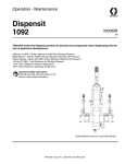
Meter, mix and dispense system for precise two-component micro-dispensing of sealants
and adhesives. Not for use in explosive atmospheres.
Important Safety Instructions
Read all warnings and instructions in this
manual. Save these instructions.
See page 3 for model information, including maximum
working pressure and approvals.
Micrometer PD44 and LRT PD44 Control Box shown
Contents
Related Manuals . . . . . . . . . . . . . . . . . . . . . . . . . . . 3
Models . . . . . . . . . . . . . . . . . . . . . . . . . . . . . . . . . . . 3
Warnings . . . . . . . . . . . . . . . . . . . . . . . . . . . . . . . . . 4
Component Identification . . . . . . . . . . . . . . . . . . . . 6
Control Boxes . . . . . . . . . . . . . . . . . . . . . . . . . . . 6
PD44 Dispense Valve . . . . . . . . . . . . . . . . . . . . . 8
Grounding . . . . . . . . . . . . . . . . . . . . . . . . . . . . . . . . 9
Setup . . . . . . . . . . . . . . . . . . . . . . . . . . . . . . . . . . . . 10
Micrometer and LRT PD44 Only . . . . . . . . . . . . 10
Motor Driven PD44 Only . . . . . . . . . . . . . . . . . . 11
Startup . . . . . . . . . . . . . . . . . . . . . . . . . . . . . . . . . . 12
Dispensing Operation . . . . . . . . . . . . . . . . . . . . . . 13
HMI Operation . . . . . . . . . . . . . . . . . . . . . . . . . . . . 14
Screen Navigation Diagrams . . . . . . . . . . . . . . 14
Main Screen . . . . . . . . . . . . . . . . . . . . . . . . . . . 16
Posidot Control Screen
(Micrometer PD44 and
LRT PD44 only) . . . . . . . . . . . . . . . . . . . . . 17
Metering Valve Control Screen
(Motor Driven PD44 only) . . . . . . . . . . . . . . 18
Shot Size Screen
(LRT PD44 only) . . . . . . . . . . . . . . . . . . . . . 20
Shot Size Screen
(Motor Driven PD44 Only) . . . . . . . . . . . . . 21
Level 1 Control Screen . . . . . . . . . . . . . . . . . . . 22
Level 2 Control Screen . . . . . . . . . . . . . . . . . . . 23
Purge Timer Screen . . . . . . . . . . . . . . . . . . . . . 25
Status Screen . . . . . . . . . . . . . . . . . . . . . . . . . . 28
Motor Status Screen
(Motor Driven PD44 only) . . . . . . . . . . . . . . 30
Motor Error Codes Screen
(Motor Driven PD44 Only) . . . . . . . . . . . . . 32
Supervisor Screen
(LRT PD44 Only) . . . . . . . . . . . . . . . . . . . . 33
Supervisor Screen
(Motor Driven PD44 Only) . . . . . . . . . . . . . 34
Supervisor Help Screen
(Motor Driven PD44 Only) . . . . . . . . . . . . . 35
Calibration Screen
(LRT PD44 Only) . . . . . . . . . . . . . . . . . . . . 36
2
Pressure Relief Procedure . . . . . . . . . . . . . . . . . . 38
Shutdown . . . . . . . . . . . . . . . . . . . . . . . . . . . . . . . . 38
Optional Customer Inputs . . . . . . . . . . . . . . . . . . . 39
Maintenance . . . . . . . . . . . . . . . . . . . . . . . . . . . . . . 40
Troubleshooting . . . . . . . . . . . . . . . . . . . . . . . . . . . 40
Technical Data . . . . . . . . . . . . . . . . . . . . . . . . . . . . 41
Graco Standard Warranty . . . . . . . . . . . . . . . . . . . 42
Graco Information . . . . . . . . . . . . . . . . . . . . . . . . . 42
313877E
Related Manuals
Related Manuals
PD44 Manuals
Part
Description
313876
PD44 Dispense Valve Operation - Parts
Feed System Manuals
306565
Air-Driven, Stainless Steel Agitators
307043
Monark® Air Motor
308116
Severe-Duty, UHMWPE/PTFE or PTFE
Packed Stainless Steel Pumps
308167
Low Volume Air Regulators
308168
High Volume Air Regulators
308169
Air Filters, Lubricators and Kits
309306
Air-Operated Husky™ Diaphragm Pumps
312376
Stainless Steel Agitator Kit
313526
Check-Mate® Pump Packages
406088
Check-Mate® Ram Packages
Models
PD44 Control Box
Model
Linear Resistive
Transducer (LRT)
Max Air Working
Pressure
psi (MPa, bar)
Voltage
CE Approved*
100 (0.7, 7)
120/240V,
50/60Hz
✔
100 (0.7, 7)
120/240V,
50/60Hz
✔
100 (0.7, 7)
120/240V,
50/60Hz
✔
Micrometer
Motor Driven
*
If a custom PD44 is ordered, it will not be CE
approved unless otherwise noted.
313877E
3
Warnings
Warnings
The following warnings are for the setup, use, grounding, maintenance, and repair of this equipment. The exclamation point symbol alerts you to a general warning and the hazard symbol refers to procedure-specific risk. Refer back
to these warnings. Additional, product-specific warnings may be found throughout the body of this manual where
applicable.
WARNING
TOXIC FLUID OR FUMES HAZARD
Toxic fluids or fumes can cause serious injury or death if splashed in the eyes or on skin, inhaled, or
swallowed.
• Read MSDS’s to know the specific hazards of the fluids you are using.
• Store hazardous fluid in approved containers, and dispose of it according to applicable guidelines.
• Always wear impervious gloves when spraying or cleaning equipment.
• If this equipment is used with isocyanate material, see additional information on isocyanates in Isocyanate Conditions Section of this manual.
PERSONAL PROTECTIVE EQUIPMENT
You must wear appropriate protective equipment when operating, servicing, or when in the operating
area of the equipment to help protect you from serious injury, including eye injury, inhalation of toxic
fumes, burns, and hearing loss. This equipment includes but is not limited to:
• Protective eyewear
• Clothing and respirator as recommended by the fluid and solvent manufacturer
• Gloves
• Hearing protection
FIRE AND EXPLOSION HAZARD
Flammable fumes, such as solvent and paint fumes, in work area can ignite or explode. To help prevent
fire and explosion:
• Use equipment only in well ventilated area.
• Eliminate all ignition sources; such as pilot lights, cigarettes, portable electric lamps, and plastic drop
cloths (potential static arc).
• Keep work area free of debris, including solvent, rags and gasoline.
• Do not plug or unplug power cords, or turn power or light switches on or off when flammable fumes
are present.
• Ground all equipment in the work area. See Grounding instructions.
• Use only grounded hoses.
• Hold gun firmly to side of grounded pail when triggering into pail.
• If there is static sparking or you feel a shock, stop operation immediately. Do not use equipment
until you identify and correct the problem.
• Keep a working fire extinguisher in the work area.
ELECTRIC SHOCK HAZARD
This equipment must be grounded. Improper grounding, setup, or usage of the system can cause electric shock.
• Turn off and disconnect power cord before servicing equipment.
• Use only grounded electrical outlets.
• Use only 3-wire extension cords.
• Ensure ground prongs are intact on power and extension cords.
• Do not expose to rain. Store indoors.
4
313877E
Warnings
WARNING
PRESSURIZED EQUIPMENT HAZARD
Fluid from the gun/dispense valve, leaks, or ruptured components can splash in the eyes or on skin and
cause serious injury.
• Follow Pressure Relief Procedure in this manual, when you stop spraying and before cleaning,
checking, or servicing equipment.
• Tighten all fluid connections before operating the equipment.
• Check hoses, tubes, and couplings daily. Replace worn or damaged parts immediately.
EQUIPMENT MISUSE HAZARD
Misuse can cause death or serious injury.
• Do not operate the unit when fatigued or under the influence of drugs or alcohol.
• Do not exceed the maximum working pressure or temperature rating of the lowest rated system
component. See Technical Data in all equipment manuals.
• Do not leave the work area while equipment is energized or under pressure. Turn off all equipment
and follow the Pressure Relief Procedure in this manual when equipment is not in use.
• Check equipment daily. Repair or replace worn or damaged parts immediately with genuine manufacturer’s replacement parts only.
• Do not alter or modify equipment.
• Use equipment only for its intended purpose. Call your distributor for information.
• Route hoses and cables away from traffic areas, sharp edges, moving parts, and hot surfaces.
• Do not kink or over bend hoses or use hoses to pull equipment.
• Keep children and animals away from work area.
• Comply with all applicable safety regulations.
PLASTIC PARTS CLEANING SOLVENT HAZARD
Use only compatible water-based solvents to clean plastic structural or pressure-containing parts. Many
solvents can degrade plastic parts and cause them to fail, which could cause serious injury or property
damage. See Technical Data in this and all other equipment instruction manuals. Read fluid and solvent
manufacturer’s warnings.
313877E
5
Component Identification
Component Identification
Control Boxes
A
B
D
C
H
J
A TANK
LEVEL CONTROLS
G
B TANK
LEVEL CONTROLS
F
CUSTOMER I/O
SIGNAL CONNECTION
2 1
5 4 3
7 6
2 1
5 4 3
7 6
2 1
5 4 3
7 6
PG-3
PG-4
PG-2
START
E
L
100V TO 250V AC
1
3
2
4
PG-8
MACHINE I/O
3
2
7
6
11
1
5
10
14
4
9
13
8
12
PG-1
SPOOL
VALVE
T
S
M
N
AIR
CYLINDER
108
107
106
105
LOAD
DISP
EXT
RET
P
R
K
Key:
A
B
C
D
E
F
G
H
J
Emergency Stop
Control Power Switch
Touch Panel
Alarm Speaker
Power Input
Start Options Connection
Custom I/O
A Tank Level Controls Connection
B Tank Level Controls Connection
K
L
M
N
P
R
S
T
Main Air Inlet
Dispense Valve I/O Connection
Spool Valve Load Connection
Spool Valve Dispense Connection
Air Cylinder Extend Connection
Air Cylinder Retract Connection
Air Pressure Regulator
Air Pressure Gauge
FIG. 1: Micrometer and LRT PD44 Control Box
6
313877E
Component Identification
B
A
C
CONTROL POWER
D
AUDIO ALARM
START OPTIONS
4
1
3
2
MOTOR
VALVE I/O
F
VERIFY INCOMING VOLTAGE
WITH VOLTAGE SWITCH SETTING
BEFORE CONNECTING POWER
L
U
E
J
H
Key:
A
B
C
D
E
Emergency Stop
Control Power Switch
Touch Panel
Alarm Speaker
Power Input
F
H
J
L
U
Start Options Connection
A Tank Level Controls Connection
B Tank Level Controls Connection
Dispense Valve I/O Connection
Motor Connection
FIG. 2: Motor Driven PD44 Control Box
313877E
7
Component Identification
PD44 Dispense Valve
See PD44 Operation manual 313876 for detailed dispense valve component identification and instructions.
FIG. 3: PD44 Micrometer Dispense Valve
8
313877E
Grounding
Grounding
This product must be grounded. In the event of an electrical short circuit, grounding reduces the risk of electric
shock by providing an escape wire for the electric current.
Grounding plug units: this product is equipped with a
cord having a grounding wire with an appropriate
grounding plug. The plug must be plugged into an outlet
that is properly installed and grounded in accordance
with all local codes and ordinances.
Hard-wired units: the grounding wire must be used. All
electrical wiring must be done by a qualified electrician
and comply with all local codes and regulations.
Air and fluid hoses: use only electrically conductive
hoses.
Fluid supply container: follow local code.
Solvent pails used when flushing: follow local code.
Use only conductive metal pails, placed on a grounded
surface. Do not place the pail on a non-conductive surface, such as paper or cardboard, which interrupts
grounding continuity.
313877E
9
Setup
Setup
Micrometer and LRT PD44 Only
3. Connect Dispense Valve I/O, and Start Options
logic cables. If level controls are installed, connect
Level Controls logic cables.
NOTICE
Feed system and main logic control system must
use separate air supplies.
1. Connect air supply to main air inlet on control box.
Air supply must include a shut-off/bleed valve that
bleeds pressure past the shut-off/bleed valve and an
air-water separator/filter.
A TANK
LEVEL CONTROLS
A TANK
LEVEL CONTROLS
B TANK
LEVEL CONTROLS
CUSTOMER I/O
SIGNAL CONNECTION
START
B TANK
LEVEL CONTROLS
CUSTOMER I/O
SIGNAL CONNECTION
2 1
5 4 3
7 6
2 1
5 4 3
7 6
2 1
5 4 3
7 6
PG-3
PG-4
PG-2
START
100V TO 250V AC
1
3
2
4
PG-8
MACHINE I/O
100V TO 250V AC
3
2
7
2 1
5 4 3
7 6
2 1
5 4 3
7 6
2 1
5 4 3
7 6
PG-3
PG-4
PG-2
3
6
11
1
1
5
10
14
2
4
9
13
8
12
4
PG-1
PG-8
MACHINE I/O
3
2
7
6
11
1
5
10
14
4
9
13
8
SPOOL
VALVE
AIR
CYLINDER
12
108
107
106
105
LOAD
DISP
EXT
RET
PG-1
SPOOL
VALVE
AIR
CYLINDER
108
107
106
105
LOAD
DISP
EXT
RET
4. Adjust air pressure regulator to 80 psi (0.6 MPa,
6 bar).
2. Connect air lines from control box to dispense valve.
Match the number and color codes on the fittings
and connections. See the following table and illustration.
Connection
Color
Red
Blue
Yellow
Green
5. Perform Setup procedure for dispense valve and
feed system components. See Related Manuals on
page 3.
Connection
Description
Extend
Retract
Dispense
Reload
A TANK
LEVEL CONTROLS
B TANK
LEVEL CONTROLS
CUSTOMER I/O
SIGNAL CONNECTION
2 1
5 4 3
7 6
2 1
5 4 3
7 6
2 1
5 4 3
7 6
PG-3
PG-4
PG-2
START
100V TO 250V AC
1
3
2
4
PG-8
MACHINE I/O
3
2
7
6
11
1
5
10
14
4
9
13
8
12
PG-1
SPOOL
VALVE
10
AIR
CYLINDER
108
107
106
105
LOAD
DISP
EXT
RET
313877E
Setup
Motor Driven PD44 Only
1. Connect Dispense Valve I/O, Start Options, and
Motor logic cables. If level controls are installed,
connect Level Controls logic cables.
NOTICE
Feed system and main logic control system must
use separate air supplies.
AUDIO ALARM
START OPTIONS
4
1
3
2
VALVE I/O
MOTOR
VERIFY INCOMING VOLTAGE
WITH VOLTAGE SWITCH SETTING
BEFORE CONNECTING POWER
2. Adjust customer supplied air pressure regulator to
80 psi (0.6 MPa, 6 bar).
3. Perform Setup procedure for dispense valve and
feed system components. See Related Manuals on
page 3.
313877E
11
Startup
Startup
NOTE: See HMI Operation starting on page 14 for
detailed HMI instructions.
1. Press the Control Power On button.
2. On Micrometer and LRT PD44s, navigate to the
Posidot® Control screen.
On Motor Driven PD44s, navigate to the Metering
Valve Control screen.
3. Under Posidot Mode, press the Retract button.
NOTE: On LRT and Motor Driven PD44s, when there
is an Emergency Stop condition or the system power is
lost, the shot selection resets to “0”. The operator must
then select a shot.
NOTE: On Micrometer PD44s, skip steps 4-7.
4. Navigate to the Shot Size screen.
5. Select a shot number.
6. Navigate to the Pump Mode screen.
7. Press the Shot button to select Shot Mode.
8. Verify air pressure is set to 80 psi (5.6 bar).
9. Perform feed system startup procedure(s). See
Related Manuals on page 3.
10. Perform dispense valve startup procedure. See
Related Manuals on page 3.
12
313877E
Dispensing Operation
Dispensing Operation
NOTE: See HMI Operation on page 14 for detailed HMI
instructions.
The foot switch, the “Start” button, and the optional Customer Start Signal can be used to initiate shots. These
are referred to as start devices.
Retract Piston
1. On Micrometer and LRT PD44s, navigate to the
Posidot Control screen.
On Motor Driven PD44s, navigate to the Metering
Valve Control screen.
2. Under Posidot Mode, press the Retract button.
Extend Piston
Perform a Shot
1. On Micrometer and LRT PD44s, navigate to the
Posidot Control screen.
On Motor Driven PD44s, navigate to the Metering
Valve Control screen.
1. On Micrometer and LRT PD44s, navigate to the
Posidot Control screen.
On Motor Driven PD44s, navigate to the Metering
Valve Control screen.
2. Under Posidot Mode, press the Extend button.
2. Under Posidot Mode, press the Retract button.
3. Press the Shot button to select Shot Mode.
4. Press and release the start device to perform one
shot.
Dispense Continuously
The valve dispenses continuously until the end of the
stroke is reached.
1. On Micrometer and LRT PD44s, navigate to the
Posidot Control screen.
On Motor Driven PD44s, navigate to the Metering
Valve Control screen.
2. Under Posidot Mode, press the Retract button.
3. Press the Continuous button.
4. On Micrometer and LRT PD44s, press and release
the start device. Under Posidot Mode, press the
Retract button to stop dispensing and retract the
metering rods.
On Motor Driven PD44s, press and hold the start
device to dispense continuously. Release the start
device to stop dispensing and retract the metering
rods.
313877E
13
HMI Operation
HMI Operation
Screen Navigation Diagrams
Micrometer PD44
Main Screen
Status
Purge Timer
Level 1 Control
Level 2 Control
Posidot Control
FIG. 4
LRT PD44
Main Screen
Posidot Control
Shot Size/Flow Rate
Level 1 Control
Level 2 Control
Purge Timer
Status
Supervisor
Calibration
Calibration Help
FIG. 5
14
313877E
HMI Operation
Motor Driven PD44
Main Screen
Metering Valve Control
Shot Size/Flow Rate
Level 1 Control
Level 2 Control
Purge Timer
Status
Supervisor
Motor Status
Motor Error Codes
Supervisor Help
FIG. 6
313877E
15
HMI Operation
Main Screen
NOTE: The Error Code button is shown on every screen
on the Motor Driven PD44.
Motor Driven PD44 Main Screen shown
Screen Access Buttons
Error Code (Motor Driven PD44 only)
All buttons on the main screen except for the Password
and Error Code buttons open a new specified screen.
For example, pressing the “Status” button opens the
Status screen. The Password and Error Code buttons
are only on the Motor Driven PD44 screens.
NOTE: The Error Code button is shown on every screen
on the Motor Driven PD44.
Password (Motor Driven PD44 only)
On all screens that it is shown, the Error Code button
resets the error seen in the error string (shown as
“<0000000000”) and the error code number (shown as
“<000”). See the Motor Error Codes screen for more
information, page 32.
The password button enables the user to changes
values in certain screens.
To access the password press the Password Access
button (shown as “=0000”). When the keyboard appears
enter password “5810” then press the Enter key.
16
313877E
HMI Operation
Posidot Control Screen
(Micrometer PD44 and
LRT PD44 only)
NOTE: A “1” indicates that the button is in the “ON” position. A “0” indicates that the button is in the “OFF” position.
LRT PD44 Posidot Control screen shown
Start button
Continuous Mode
When the Start button is pressed, the machine starts
the cycle for the selected Pump Mode.
The machine continually cycles the pumps when the
START DEVICE is pressed.
Pump Mode
Purge Timer On /Off
NOTE: The metering rods must be retracted prior to
changing any setting under Pump Mode. See Retract
Piston, page 13.
See Purge Timer screen for definition, page 25.
Retract Mode
The air cylinder and pumps immediately retract and
remain in the retracted position. This is used for maintenance purposes only.
Dwell Timer
(LRT and Motor Driven Only)
See Purge Timer screen for definition, page 25.
Cycle Counter On /Off
(Micrometer PD44 Only)
Extend Mode
Cycle Counter not shown. See Purge Timer screen for
definition, page 25.
The air cylinder and pumps immediately extend and
remain in the extended position. This is the position that
must be selected when the pump is idle for a long period
of time.
Select Shot Size
(LRT PD44 Only)
Shot Mode
The machine fully cycles the number of times displayed
in the Cycle Counter field when the start device is
pressed and released. The machine cycles continuously
when the start device is pressed and held.
See Shot Size screen for definition, page 20.
Number of Strokes
(LRT PD44 Only)
See Shot Size screen for definition, page 20.
Amount per Stroke
(LRT PD44 Only)
See Shot Size screen for definition, page 20.
313877E
17
HMI Operation
Metering Valve Control Screen
(Motor Driven PD44 only)
NOTE: A “1” indicates that the button is in the “ON” position. A “0” indicates that the button is in the “OFF” position.
NOTE: The Error Code button is shown on every screen
on the Motor Driven PD44. See the Main screen for definition.
Start button
Extend Mode
When the Start button is pressed, the machine starts
the cycle for the selected Pump Mode.
The air cylinder and pumps immediately extend and
remain in the extended position. This position must be
selected when the pump is idle for a long period of time.
Pump Mode
NOTE: The metering rods must be retracted prior to
changing any setting under Pump Mode. See Retract
Piston, page 13.
Retract Mode
The air cylinder and pumps immediately retract and
remain in the retracted position. This is used for maintenance purposes only.
18
Shot Mode
The machine cycles the number of times displayed in
the Cycle Counter field when the start device is pressed
and released. The machine cycles continuously when
the start device is pressed and held.
Continuous (Operator Control) Mode
In this mode, the machine to dispense while the start
device is pressed. When the start device is released the
metering rods retract to the home position.
313877E
HMI Operation
DV Valve Mode
This mode actuates an optional dispense valve.
OPEN
In this mode, the dispense valve is held in the open position, allowing material to pass through.
AUTO
In this mode, the dispsense valve opens automatically
whenever the pump is cycled.
CLOSE
In this mode, the dispense valve is held closed.
313877E
19
HMI Operation
Shot Size Screen
(LRT PD44 only)
NOTE: This section describes the Shot Size screen for
the LRT PD44 only. See page 21 for the Motor Driven
PD44 Shot Size screen.
NOTICE
Erratic operation results if the shot size value entered is
not greater than the absolute value of the Shot Size Offset setting. For example, if the Shot Size Offset setting
is -1%, a shot size greater than 1% must be entered.
See Supervisor screen, page 33.
Shot Size 1 – 10
The Shot Size 1 - 10 buttons allow the operator to program 10 different shot sizes. Shot size is percent of
stroke. Once the shot sizes are programmed the shot
number can be selected using the Select Shot Size button.
To change the Shot Size 1-10 setting, perform the following steps.
Select Shot Size button
The Select Shot Size button allows the operator to
choose one of the ten preset shot sizes seen in the Shot
Size 1 - 10 section.
Number of Strokes
This displays the number of strokes needed to perform
the selected shot. If the Shot Size selected is 150% then
Number of Strokes displays a “2” because the machine
performs two strokes at 75% of the full stroke.
Amount per Stroke in %
This displays the percent of stroke used to perform the
selected shot. If the Shot Size selected is 150% then the
Amount per Stroke in % displays “75” because the
machine performs 2 strokes using 75% of the full stroke
length.
1. Select one of the Shot Size 1-10 buttons. A numeric
keypad appears.
2. Enter the desired material shot size volume in percent of stroke. For example, enter “150” to dispense
material volume equivalent to 1.5 strokes.
3. Press the
button. The keypad disappears. The
new shot size percentage appears in the Shot Size
field.
20
313877E
HMI Operation
Shot Size Screen
(Motor Driven PD44 Only)
NOTE: This section describes the Shot Size screen for
the Motor Driven PD44 only. See page 20 for the LRT
PD44 Shot Size screen.
NOTICE
Erratic operation results if the shot size value entered is
not greater than the absolute value of the Shot Size Offset setting. For example, if the Shot Size Offset setting
is -1%, a shot size greater than 1% must be entered.
See Supervisor screen, page 34.
Select Shot Size/Flow Rate Combination
Use this to change the selected shot by entering a number between 1 and 7. The selected shot size and flow
rate is shown in the Shot Size (percent) section and
Flow Rate (mm/sec) section.
Number of Strokes
This displays the number of shots of material when the
machine is dispensing.
For example, if the purge shot size is set at 150%, Number of Strokes displays a “2”, and the Amount Per
Stroke % displays “75.00”.
Shot Size (percent), Flow Rate (mm/sec)
These are the 7 preset Shot Size (percent) and Flow
Rate (mm/sec) values. Shot size is in percent of stroke.
The preset values can be selected using Select Shot
Size/Flow Rate Combination.
To edit the preset Shot Size or Flow Rate values, log-in
as the supervisor. See Main Screen, page 16.
Below is the minimum and maximum field allowance for
this design.
Shot Size:
Minimum = 2.5%
Maximum = 500.0%
Flow Rate:
Minimum = 0.50 mm/second
Maximum = 25.00 mm/second
Amount Per Stroke %
This displays the stroke per shot in percent of stroke.
For example, if the purge shot size is set at 340%,
Amount Per Stroke % displays “85.00” and Number of
Strokes During Purge displays a “4”.
313877E
21
HMI Operation
Level 1 Control Screen
NOTE: The Error Code button is shown on every screen
on the Motor Driven PD44. See the Main screen for definition, page 16.
NOTE: If ‘A Tank Status’ and ‘B Tank Status’ both display 'Levels Not Active' then the level control feature is
not installed on this machine.
Micrometer PD44 and LRT PD44 Level 2 Control screen shown
A Tank Status, B Tank Status
Start Fill A, Start Fill B button
This displays information about each component tank
filling process. The following are the possible messages.
Message
Description
Material
High
The tank level is at or above the high level sensor.
Material
Low
The tank level is below the low level sensor.
Filling
The tank is currently refilling in the tank refilling
process.
Material
Present
The tank level is between the high and the low
level sensors.
Level Sensor Fault
The machine senses material at the high level
sensor but not at the low level sensor.
Stop Fill button
Levels Not
Active
Level sensors are not installed for the tank.
This button stops the automatic tank refilling process for
both the A and B component material tanks.
Fill Fault
The tank began refilling and the fluid level did not
reach the high level sensor within the preset time
entered into the Fill Timer button seen in the
Level2 Control screen. Tank has stopped refilling.
When this button is pressed the transfer pump fills the
tank until the material level reaches the high level sensor on that tank.
NOTE: The Start Fill A, Start Fill B and the Stop Fill buttons are inoperable if the high level automatic tank refilling feature was not purchased with this machine.
Silence Alarm button
This button silences the audible alarm when pressed.
22
313877E
HMI Operation
Level 2 Control Screen
NOTE: A “1” indicates that the button is in the “ON” position. A “0” indicates that the button is in the “OFF” position.
NOTE: The Error Code button is shown on every screen
on the Motor Driven PD44. See the Main screen for definition, page 16.
NOTE: In the Level 1 Control Screen, if ‘A Tank Status’
and ‘B Tank Status’ both display 'Levels Not Active' then
the level control feature is not installed on this machine.
Press the Main button to exit from this screen.
Micrometer PD44 and LRT PD44 Level 1 Control screen shown
Low Level Shutdown button
Clear Fill Fault button
When this button displays ‘1’ and the material level of
either the ‘A’ component tank or the ‘B’ component tank
goes below the low level sensor, the machine shuts
down. To recover, refill the component tank with material
to above the low level sensor. When ‘0’ is displayed, the
low level shutdown feature is disabled.
This button clears the Fill Timer Fault message displayed in the corresponding ‘A Tank Status’ or ‘B Tank
Status’ field in the Level 1 Control screen.
Alarm Engage button
Silence Alarm button
Press this button to silence the low fluid level audible
alarm. The audible alarm will be activated again when
the low level condition reoccurs.
When this button displays ‘1’ and the material level of
either the ‘A’ component tank or the ‘B’ component tank
goes below the low level sensor the audible alarm is
activated.
Auto Fill Engage button
When this button displays ‘1’ the automatic filling function is activated.
313877E
23
HMI Operation
Shutdown Timer button/indicator
NOTE: If the level control option has not been purchased the Shutdown Timer button is disabled.
This changes the delay before the Fill Timer Fault message is displayed in the corresponding ‘A Tank Status’ or
‘B Tank Status’ field on the Level 1 Control screen. If the
material level is below the low level sensor for more than
the duration of the Shutdown Timer setting, the machine
shuts down.
NOTE: For example, if 15 is entered, the Fill Timer setting is 1.5 seconds.
3. Press the
button. The new Fill Timer setting
appears in the Fill Timer field.
NOTE: The current Fill Timer time is shown by
“<00000”. This counts up to the preset time.
To change the Shutdown Timer setting, perform the following steps.
1. Select the Shutdown Timer button (shown as
“=00000”). A numeric keypad appears.
2. Enter the desired Shutdown Timer setting in tenths
of a second.
NOTE: For example, if 15 is entered, the shutdown time
is 1.5 seconds.
3. Press the
button. The new Shutdown Timer setting is shown.
NOTE: The current time of the Shutdown Timer is
shown by “<00000”. This counts up to the preset time.
Fill Timer
NOTE: If the automatic refilling option has not been purchased the Fill Timer function is disabled.
This changes the delay before the Fill Timer Fault message is displayed to the corresponding ‘A Tank Status’
or ‘B Tank Status’ field in the Level 1 Control screen. If
the material level reaches the tank high level sensor
before the preset fill time elapses, the ‘Tank High Level’
message is displayed in the Tank Status field and the Fill
Timer is reset. If the preset fill time expires before material reaches the high level sensor, “Fill Timer Fault”
appears in the Level1 Control Screen.
To change the Fill Timer setting, perform the following
steps.
1. Select the Fill Timer button (shown as “=00000”). A
numeric keypad appears.
2. Enter in the Fill Timer time in tenths of a second.
24
313877E
HMI Operation
Purge Timer Screen
NOTE: The Error Code button is shown on every screen
on the Motor Driven PD44. See the Main screen for definition, page 16.
NOTE: On the Micrometer PD44, the “Purge Timer
screen” is named the “Timer/Counter Screen.”
Motor Driven PD44 Purge Timer Screen Shown
Cycle Counter On/Off button (Micrometer PD44
Only, Not Shown)
Purge Timer On /Off
The Cycle Counter switch is used to enable/disable the
cycle counter.
OFF: The Cycle Counter is disabled.
ON: If Shot Mode is selected, when the Cycle Counter is
enabled the number of cycles entered are dispensed.
Always set the dwell/alarm timer to a value that will
give the user adequate warning that the machine is
about to dispense a purge shot.See Dwell / Alarm
Timer section on page 26.
To change the Cycle Counter value, perform the following steps.
The Purge Timer On/Off switch is used to enable/disable the Purge Timer.
1. Select the Cycle Counter button. A numeric keypad
appears.
OFF: The Purge Timer is disabled.
2. Enter in the desired number of counts for the Cycle
Counter.
ON: The Purge Timer is enabled. The machine initiates
a purge shot when the purge timer expires provided the
fluid ball valves are open, Shot Mode is selected, and no
errors exist.
3. Press the Enter button. The current number of
cycles appears in the Cycle Counter field.
313877E
25
HMI Operation
Dwell / Alarm Timer
Enter Purge Time Button
The Enter Purge Time button is shown as “=000.0”
below the Purge Timer On /Off button. The Enter Purge
Time button allows the operator to set the required time
between cycles. When the Purge Timer switch is in the
ON position and the Pump Mode switch is in the Shot or
Operator Control position, the purge timer unit counts up
to the preset time. When it reaches the preset time, a
purge shot is initiated.
The timer then automatically resets and continues with
the sequence of cycling and resetting. It continues until
the Purge Timer is turned to the OFF position.
Always set the dwell/alarm timer to a value that will
give the user adequate warning that the machine is
about to dispense a purge shot.
This changes the duration that the audible alarm is
active prior to the purge shot being initiated.
To change the Dwell Timer, perform the following steps.
To change the Purge Timer setting, perform the following steps.
1. Select the Dwell Timer button. A numeric keypad
appears.
1. Select Purge Timer button. A numeric keypad
appears.
2. Enter the desired Dwell Timer time in seconds. Use
the “.” button to enter tenths of seconds.
2. Enter the desired purge time in seconds. Use the “.”
button to enter tenths of a second.
3. Press the
button. The new Dwell Timer time
appears in the Dwell Timer field.
3. Press the
button. The Purge Timer screen
appears. The new purge time appears in the Purge
Timer button.
NOTE: The current Dwell Timer time is shown by
<000.0.
NOTE: The current Purge Timer time is shown in the
bottom text box below the Purge Timer button.
Calculating the Purge Timer Setting
If the shot size is larger than the mixer volume, set the
timer for one-half the gel time of the material. If the shot
size is smaller, use the following formula to determine
the Purge Timer setting.
Gel Time X Shot Size
= Timer Setting
2 X Mixer Volume
For example, with mixer volume = 13.3cc, shot size =
10cc, gel time = 10 minutes, use the following equation.
10 min X 10 cc
This button shows the Shot Size volume in percent of
stroke. This volume is dispensed during the ratio check.
To change the Purge Shot Size % volume, perform the
following steps.
1. Select Purge Shot Size % button. A numeric keypad
appears.
2. Enter the desired material shot size volume.
3. Press the
button. The Purge Timer screen
appears. The new shot size percentage appears in
the Purge Shot Size % field.
100 cc*min
=
2 X 13.3 cc
Purge Shot Size % button (LRT and Motor Driven
PD44 only)
= 3.76 min
26.6 cc
Number of Strokes During Purge button/indicator
(LRT and Motor Driven PD44 only)
This displays the number of strokes used during the
purge shot.
For example, if the purge shot size is set at 150%, Number of Strokes During Purge displays “2” and Amount
Per Stroke % displays “75”.
26
313877E
HMI Operation
Amount Per Stroke % (LRT and Motor Driven PD44
only)
This displays the percent of the stroke used during a
shot.
For example, if the shot size is set at 150%, Number of
Strokes During Purge displays “2” and Amount Per
Stroke % displays “75”.
313877E
27
HMI Operation
Status Screen
NOTE: A “1” indicates that the button is in the “ON” position. A “0” indicates that the button is in the “OFF” position.
NOTE: The Error Code button is shown on every screen
on the Motor Driven PD44. See the Main screen for definition, page 16.
Micrometer PD44 and LRT PD44 Status Screen Shown
Maintenance Totalizer
This counter increments each time the machine cycles.
Press the Reset Maintenance Totalizer button to reset.
This counter is used for maintenance purposes.
Amount per Stroke in % (Motor Driven PD44 Only,
not shown)
This displays the amount of stroke used to perform the
currently selected shot. If the shot size is 150%, Amount
per Stroke in % displays “75%”.
# Of Times Maintenance Totalizer has been Reset
This counter increments each time the Reset Maintenance Totalizer button is pressed.
Reset Maintenance Totalizer button
This button resets the Maintenance Totalizer.
Cycle Totalizer
Dispense Ready
This displays “1” if the metering rods are loaded with
material and ready to dispense. It displays a “0” if the
metering tube is reloading or at the end of the dispense
cycle. Customer Signal Integration Kit 80/2450/CS/50,
which uses this output, can be ordered separately. The
Customer Signal Integration Kit is standard on Motor
Driven PD44s.
This counter increments each time the machine cycles.
Number of Strokes (Motor Driven PD44 Only, not
shown)
This displays the number of strokes needed to perform
the currently selected shot size. If the selected shot size
is 150%, Number of Strokes displays a “2”.
28
313877E
HMI Operation
Dispense Complete
This displays “1” if the metering rods are reloaded with
material or at the end of the dispense cycle, and displays a “0” if the metering tube is loaded with material
and ready to dispense. Customer Signal Integration Kit
80/2450/CS/50, which uses this output, can be ordered
separately. The Customer Signal Integration Kit is standard on Motor Driven PD44s.
Contrast + button
This button increases the contrast of the screen.
Contrast - button
This button decreases the contrast of the screen.
PX-CSV Reload
This displays the status of the reload spool proximity
switch. If this displays a “1” the switch is activated and if
this displays a “0” the switch is deactivated. See Component Identification section in dispense valve manual.
See Related Manuals on page 3.
PX-OSV Dispense
This displays the status of the dispense spool proximity
switch. If this displays a “1” the switch is activated. If this
displays a “0” the switch is deactivated. See component
identification section in dispense valve manual. See
Related Manuals on page 3.
PLC Program (Micrometer and LRT PD44 only)
This gives the currently installed PLC program version
and revision level.
HMI Program (Micrometer and LRT PD44 only)
This gives the currently installed HMI program version
and revision level.
313877E
29
HMI Operation
Motor Status Screen
(Motor Driven PD44 only)
NOTE: A “1” indicates that the button is in the “ON” position. A “0” indicates that the button is in the “OFF” position.
NOTE: The Error Code button is shown on every screen
on the Motor Driven PD44. See the Main screen for definition, page 16.
To navigate to the Motor Status screen, press the “Motor
Status” button on the Status screen.
CSV Switch (Closed Spool Valve Switch)
This displays “1” when the spool valve is in the closed or
reload position.
Lower Switch (Lower Over Limit Switch, Retract)
This displays “1” when the metering valve rod lower
over-travel limit switch is activated. The dispense valve
is in the most-extended position. Put the dispense valve
in this position when it is idle for a long period of time.
Motor Position (Steps)
OSV Switch (Open Spool Valve Switch)
This displays “1” when the spool valve is in the open or
dispense position.
This gives the motor step position in terms of transducer
steps.
Shot Size %
Home Switch (Home Limit Switch)
This displays “1” when the metering valve rod home
switch is activated.
Upper Switch (Upper Over Limit Switch, Extend)
This shows the Shot Size volume in percent of stroke.
Flow Rate (mm/sec)
This allows the operator to view the current flow rate in
millimeters per second.
This displays “1” when the metering valve rod upper
over-travel limit switch is activated. The dispense valve
is in the most-retracted position.
30
313877E
HMI Operation
Shot Mode Step #
This gives the current step in the shot mode program.
This is used for troubleshooting.
Reload Mode Step #
This gives the current step in the reload mode program.
This is used for troubleshooting.
Oper. Mode Step #
This gives the current step in the operator mode program. This is used for troubleshooting.
313877E
31
HMI Operation
Motor Error Codes Screen
(Motor Driven PD44 Only)
These screens give descriptions of the motor error
codes.
32
313877E
HMI Operation
Supervisor Screen
(LRT PD44 Only)
NOTE: This section describes the Supervisor screen for
the LRT PD44 only. See page 34 for the Motor Driven
PD44 Supervisor screen.
Pump Reload
Shot Size Offset Button
Pump Reload sets a transducer point where the
machine will reload. The point is relative to the rod
stroke mechanical limits.
Reload 3%
Shot Size Offset -1%
The Shot Size Offset button sets the transducer point
where the metering rods will retract. The factory setting
is -1.
Most
Retracted
Position
Most
Extended
Position
To change the Pump Reload setting, perform the following steps.
To change the Shot Size Offset setting, perform the following steps.
1. Press Enter Password button.
2. Enter password.
3. Press the Enter button.
4. Press the Shot Size Offset button.
1. Press Enter Password button.
5. Enter the desired Shot Size Offset.
2. Enter password.
6. Press the Enter button.
3. Press the Enter button.
7. Press the Enter Data button.
4. Press the Pump Reload Position button.
5. Enter the desired reload position.
6. Press the Enter button.
7. Press the Enter Data button.
313877E
33
HMI Operation
Supervisor Screen
(Motor Driven PD44 Only)
NOTE: This section describes the Supervisor screen for the Motor Driven PD44 only. See page 34 for the LRT PD44
Shot Size screen.
NOTE: A “1” indicates that the button is in the “ON” position. A “0” indicates that the button is in the “OFF” position.
NOTE: To change the values on this screen, log-in as
the supervisor. See Main Screen, page 16.
Error Code button
This button resets the error in the error string (shown as
“<0000000000”) and the error code number (shown as
“<000”). See the Motor Error Code screen for more
information, page 32.
Reload Setup
Only one of the three Reload Setup Options can be
enabled at any given time.
Reload After Each Shot button
In this mode, the metering rods retract after every shot.
This is the default system setup.
Reload After Multiple Shots button
In this mode, the metering rods retract only when the
metering rods are about to reach the end of the stroke.
This feature is only available when in Operator Control
mode.
34
For example, if the selected shot size is 30% of the
metering rods stroke, three shots will be taken (90% of
the stroke) then the metering rods will retract. The rods
retract after three shots because it cannot do another
shot without going over 100% stroke. If the selected shot
size is greater than 50% of the metering rods stroke, the
metering rods will retract after every shot.
Manual Reload W/ Customer Signal button
In this mode, the customer must send a signal to reload
the valve before the lower switch is activated. Otherwise,
the dispense valve will initiate a shot using the selected
shot size and flow rate combination.
NOTE: This can be linked with a PLC input for system
integration. See the logic drawings for more information.
Reload Speed (mm/sec) button
This allows the operator to change the retract or reload
speed in millimeters per second.
Feed Setup
This allows the operator to choose the low level setting
for the feed system with tanks or a feed system with cartridge or syringes. This inverts the switch function in the
PLC logic.
313877E
HMI Operation
Supervisor Help Screen
(Motor Driven PD44 Only)
This screen describes the various reload and shot
options in the Supervisor screen.
To get to the Setup Help screen, press the “Help” button
on the Supervisor screen.
313877E
35
HMI Operation
Calibration Screen
(LRT PD44 Only)
Calibrate Mode button
Transducer Position in %
When this button is selected machine calibration starts.
This shows the transducer position in percent of stroke.
Extend Pumps button
To calibrate the pumps, perform the following steps.
1. From the Calibration screen, select Calibration
Mode.
2. Press the Extend Pumps button. Pumps extend.
This extends the air cylinder for the calibration
sequence. The most-extended position is recorded
when the Teach button is then pressed.
Retract Pumps button
This retracts the air cylinder for the calibration
sequence. The most-retracted position is recorded when
the Teach button is then pressed.
Teach button
This “teaches” or stores various data collected during
calibration mode.
Done button
This button exits Calibration mode.
3. Press the Teach button.
4. Press the Retract Pumps button. Pumps retract.
5. Press the Teach button.
6. Press the Done button.
Shot Size Offset
The Shot Size Offset allows the operator to view the
shot size offset percentage. The factory default is -1%.
See the Supervisor screen, page 33.
Reload Position
Reload Position allows the operator to view the reload
position. The factory setting is 3%.
Transducer Position
This shows the transducer position in transducer units.
36
313877E
HMI Operation
Calibration Screen Help
This screen describes the calibration procedure.
313877E
37
Pressure Relief Procedure
Pressure Relief
Procedure
1. Turn main air supply shut-off/bleed valve to the off
position. This will bleed air from the system.
2. Perform feed system pressure relief procedure. See
Related Manuals on page 3.
3. Perform dispense valve pressure relief procedure.
See Related Manuals on page 3.
Shutdown
1. On Micrometer and LRT PD44s, go to the Posidot
Control screen.
On Motor Driven PD44s, go to the Metering Valve
Control screen.
2. Press the Retract button.
3. Press the Extend button.
4. Press the Emergency Stop button. Ensure everything is off.
5. Twist Emergency Stop to reset.
6. Perform Pressure Relief Procedure.
7. Perform feed system shutdown procedure. See
Related Manuals on page 3.
8. Perform dispense valve shutdown procedure. See
Related Manuals on page 3.
38
313877E
Optional Customer Inputs
Optional Customer Inputs
Micrometer PD44 and LRT PD44
Name
Description
Ready to Dispense Signal
(Output)
Cycle-Complete (Output)
Customer Start (Input)
In Shot Mode, changes state when pump is retracted and LS-EXT is tripped.
In Shot Mode, changes state for one second after the retract switch is tripped.
In any mode, operates in parallel to the footswitch. Provide a dry contact closure between black and white wires on the customer signal cable to actuate
machine.
Motor Driven PD44
Name
Description
Customer Start (Input)
When a momentary contact closure is applied to this input, the start device is
activated.
When a momentary contact closure is applied to this input, the purge shot is
activated.
When these inputs are activated in the proper sequence, the machine activates the Shot Size and Flow Rate Combination seen on the Shot Sizes
screen. See the machine logic drawings for more information.
This output activates for 2 seconds after the dispense cycle is complete.
Customer Purge Start
(Input)
Customer SS/FR Bit 1,2,3
(Input)
Customer Signal Done
(Output)
Customer Signal Dispense Ready (Output)
Customer Signal Time to
Purge (Output)
Customer Signal Open
Auxiliary Dispense Valve
(Output)
Customer Signal Reload
(Input)
313877E
This output is active when the machine is in the Shot Mode and the dispense
valve is retracted and loaded with material. This output deactivates when the
dispense valve is dispensing or if the machine is not in the shot mode.
If the Manual Reload W/ Customer Signal button under the Supervisor screen
is selected, this output is active when it is time for the machine to take a purge
shot.
NOTE: The dispense valve will not perform a purge shot until the start device
is activated.
This is to be used only when there is a metering valve feeding an on/off type
dispense valve. This signal is used to open and close the dispense valve.
When in customer reload mode, after each shot the dispense “Done” signal is
turned on for 2 seconds. During this time the customer can toggle the customer reload signal to reload the system. If the timer expires, the machines
assumes the customer does not want to reload and finishes the sequence
then turns on the ready signal and does not allow another reload until after the
next shot.
39
Maintenance
Maintenance
NOTE: If material is leaking, see Troubleshooting on
page 40.
See Related Manuals on page 3 for dispense valve and
feed system maintenance schedule and procedures.
Air-Water Separator/Filter
Drain water once a shift or as necessary.
Troubleshooting
Perform Pressure Relief Procedure before performing any troubleshooting procedure.
All Machines
Problem
Cause
Solution
Dispense valve stalling and no mate- Blocked mixer
rial being dispensed despite adequate input pressure
Flow control valve closed
Check mixer for cured material,
replace mixer as required
Open
Dispense valve not discharging normal or full volume
Low material level in reservoirs
Fill material reservoirs and prime the
machine
Air in material tanks
Fill reservoirs and prime machine
Material leaks past spool valves
Spool valve worn or damaged
Replace the spool valve and sleeve
Improper material mixing
Mixer not clean or free
Remove and replace the mixer
Material leaks around mixer while
dispensing
Cured material in mixer
Check mixer for cured material,
replace mixer
Motor Driven PD44 Only
Problem
Cause
Solution
The horn beeps after each shot
Dispense is longer than the dispense Check mixer for cured material
limit timer
The horn beeps continuously
If the low level sensors are on, the
system may be low on material
40
Check level screen for low level condition, if low level condition is present,
fill tank with material
313877E
Technical Data
Technical Data
Maximum Ambient Temperature. . . . . . . . . . . . . . . . . . . .
Maximum Operating Temp . . . . . . . . . . . . . . . . . . . . . . . .
Maximum Air Working Pressure . . . . . . . . . . . . . . . . . . . .
Supplied Air Requirements. . . . . . . . . . . . . . . . . . . . . . . .
Electrical Requirements . . . . . . . . . . . . . . . . . . . . . . . . . .
Fuses Required . . . . . . . . . . . . . . . . . . . . . . . . . . . . . . . .
110°F (43°C)
150°F (65°C)
100 psi (0.7 MPa, 7 bar)
1 to 3 cfm at 80 psi to 100 psi
120/240V, 50/60 Hz
Micrometer and LRT PD44 Control Box:
5 x 20 mm, 2A, time delay
(Graco part 81/1053-2/11, Qty = 1)
Motor Driven PD44 Control Box:
5 x 20 mm, 10A, fast, type F, 250 VAC
(Graco part V-21610P, Qty = 2)
Maximum Amperage . . . . . . . . . . . . . . . . . . . . . . . . . . . . Micrometer and LRT PD44 Control Box:
2 amps
Motor Driven PD44 Control Box:
10 amps
Dimensions (H x L x W) . . . . . . . . . . . . . . . . . . . . . . . . . . Micrometer and LRT PD44 Control Box:
13 in. x 12 in. x 15 in. (330 mm x 305 mm x 381 mm)
Motor Driven PD44 Control Box:
20 in. x 8 in. x 20 in. (508 mm x 203 mm x 508 mm)
Weight . . . . . . . . . . . . . . . . . . . . . . . . . . . . . . . . . . . . . . . Micrometer and LRT PD44 Control Box:
30 lb (13.6 kg)
Motor Driven PD44 Control Box:
60 lb (27.2 kg)
313877E
41
Graco Standard Warranty
Graco warrants all equipment referenced in this document which is manufactured by Graco and bearing its name to be free from defects in
material and workmanship on the date of sale to the original purchaser for use. With the exception of any special, extended, or limited warranty
published by Graco, Graco will, for a period of twelve months from the date of sale, repair or replace any part of the equipment determined by
Graco to be defective. This warranty applies only when the equipment is installed, operated and maintained in accordance with Graco’s written
recommendations.
This warranty does not cover, and Graco shall not be liable for general wear and tear, or any malfunction, damage or wear caused by faulty
installation, misapplication, abrasion, corrosion, inadequate or improper maintenance, negligence, accident, tampering, or substitution of
non-Graco component parts. Nor shall Graco be liable for malfunction, damage or wear caused by the incompatibility of Graco equipment with
structures, accessories, equipment or materials not supplied by Graco, or the improper design, manufacture, installation, operation or
maintenance of structures, accessories, equipment or materials not supplied by Graco.
This warranty is conditioned upon the prepaid return of the equipment claimed to be defective to an authorized Graco distributor for verification of
the claimed defect. If the claimed defect is verified, Graco will repair or replace free of charge any defective parts. The equipment will be returned
to the original purchaser transportation prepaid. If inspection of the equipment does not disclose any defect in material or workmanship, repairs will
be made at a reasonable charge, which charges may include the costs of parts, labor, and transportation.
THIS WARRANTY IS EXCLUSIVE, AND IS IN LIEU OF ANY OTHER WARRANTIES, EXPRESS OR IMPLIED, INCLUDING BUT NOT LIMITED
TO WARRANTY OF MERCHANTABILITY OR WARRANTY OF FITNESS FOR A PARTICULAR PURPOSE.
Graco’s sole obligation and buyer’s sole remedy for any breach of warranty shall be as set forth above. The buyer agrees that no other remedy
(including, but not limited to, incidental or consequential damages for lost profits, lost sales, injury to person or property, or any other incidental or
consequential loss) shall be available. Any action for breach of warranty must be brought within two (2) years of the date of sale.
GRACO MAKES NO WARRANTY, AND DISCLAIMS ALL IMPLIED WARRANTIES OF MERCHANTABILITY AND FITNESS FOR A
PARTICULAR PURPOSE, IN CONNECTION WITH ACCESSORIES, EQUIPMENT, MATERIALS OR COMPONENTS SOLD BUT NOT
MANUFACTURED BY GRACO. These items sold, but not manufactured by Graco (such as electric motors, switches, hose, etc.), are subject to
the warranty, if any, of their manufacturer. Graco will provide purchaser with reasonable assistance in making any claim for breach of these
warranties.
In no event will Graco be liable for indirect, incidental, special or consequential damages resulting from Graco supplying equipment hereunder, or
the furnishing, performance, or use of any products or other goods sold hereto, whether due to a breach of contract, breach of warranty, the
negligence of Graco, or otherwise.
FOR GRACO CANADA CUSTOMERS
The Parties acknowledge that they have required that the present document, as well as all documents, notices and legal proceedings entered into,
given or instituted pursuant hereto or relating directly or indirectly hereto, be drawn up in English. Les parties reconnaissent avoir convenu que la
rédaction du présente document sera en Anglais, ainsi que tous documents, avis et procédures judiciaires exécutés, donnés ou intentés, à la suite
de ou en rapport, directement ou indirectement, avec les procédures concernées.
Graco Information
For the latest information about Graco products, visit www.graco.com.
TO PLACE AN ORDER, contact your Graco distributor or call to identify the nearest distributor.
Toll Free: 1-800-746-1334 or Fax: 330-966-3006
All written and visual data contained in this document reflects the latest product information available at the time of publication.
Graco reserves the right to make changes at any time without notice.
For patent information, see www.graco.com/patents
Original instructions. This manual contains English. MM 313877
Graco Headquarters: Minneapolis
International Offices: Belgium, China, Japan, Korea
GRACO INC. AND SUBSIDIARIES • P.O. BOX 1441 • MINNEAPOLIS MN 55440-1441 • USA
Copyright 2009, Graco Inc. All Graco manufacturing locations are registered to ISO 9001.
www.graco.com
Revised July 2013