1
Operation - Repair - Parts / ᪢Ա⧛׃䳋䚽Ӌ
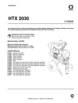
HTX 2030
313483A
- For Portable Airless and Air-Assisted Spraying of Water-Based Architectural Coatings and Paints with Base Coat Pump - For Airless Spraying Architectural Coatings and Paints with Top Coat Pump -
ͽ䗗⫽ѣ䞜⫽ᑪ㡇ⓛ⋊ᇎ∉ᗼᓏㄦ⍗᭮䖰㸡֔ᨏ᮵⇩⍗く⇩䕚ࡾᓤ⍗ͽ
ͽ䗗⫽ѣ䞜⫽䴷ⓛ⋊ᇎᓏㄦ⍗᭮䖰㸡᮵⇩⍗ͽ
IMPORTANT SAFETY INSTRUCTIONS
Read all warnings and instructions in this manual.
Save these instructions.
䞢㽖ᅞܽ䇉ᯣ
䇌䯚䇐ᴁᠠⱙݡ᠕᳞䄻ਟট䇉ᯣȢ
ֲེᄭ䖮Ѱ䇉ᯣȢ
Model Number: 257369
Maximum Working Pressure:
Base Coat Pump: 1000 psi (69 bar, 6.9 MPa)
Top Coat Pump: 3300 psi (228 bar, 22.8 MPa)
ൠৌΊ
᳕ᎺԱॠࡰΊ
ᑪ㡇ⓛ⋊ΊSVLEDU03D
䴷ⓛ⋊ΊSVLEDU03D
Related Manuals
313537 - HTX 2030 Applicator (English)
313603 - HTX 2030 Applicator (Chinese)
310894 - Displacement Pump (Top Coat)
308491 - Texture Airless Spray Gun
ⳍ݈ᠠݡ
+7;⍗ఽ 㣆᭜
+7;⍗ఽ Ђ᭜
⌐ำ⋊ 䴷ⓛ
㒎⧛⍗᭮᮵⇩ᵿ
ti13632a
Contents / ⳃᔪ
Contents / ⳃᔪ
Contents / ⳃᔪ WARNING . . . . . . . . . . . . . . . . . . . . . . . . . . . . . . . . . 3
䄻ਟ Product Overview . . . . . . . . . . . . . . . . . . . . . . . . . . 7
HTX 2030 with Base Coat Pump (257369) . . . . . 7
Top Coat Pump (Kit 24B140) . . . . . . . . . . . . . . . 8
Ѽખᘐ㾝 䞜⫽ᑪ㡇ⓛ⋊ⱙ+7; 䴷ⓛ⋊ 䜢Ӌࣚ % Component Identification - Sprayer /
䚽Ӌ䕽䅹⍗ᴏ Component Identification - Base Coat Applicator /
䚽Ӌ䕽䅹ᑪ㡇ⓛ⍗ఽ Operation / ᪢Ա Pressure Relief Procedure / ⊙ॠ℺偹 Pressure Relief Procedure / ⊙ॠ℺偹 Start Engine / 䍌ࡽদࡽᴏ Setup / 䆓㕃 Cleanup / ⏚⋬ Digital Tracking System (DTS) / ᭅᄬ䎴䏿㋐㒴 Digital Display Messages . . . . . . . . . . . . . . . . . 35
Parts / 䳋䚽Ӌ Model 257369 / ൠৌ Parts List - Model 257369 /
䳋䚽Ӌ⏚पͽൠ Pressure Control Box / ॠࡰࠋㆆ Bearing Housing / 䕉ᡔ༬ Base Coat Pump / ᑪ㡇ⓛ⋊ Base Coat Pump (Continued) /
ᑪ㡇ⓛ⋊ 㓂 Texture Applicator and Hose /
㒎⧛⍗᭮⍗ఽ䕄ㅶ Top Coat Pump Kit 24B140 (Sold Separately) /
䴷ⓛ⋊䜢Ӌࣚ % 䳕㸡䅷䌂 Wiring Diagram / 㒔 Technical Data . . . . . . . . . . . . . . . . . . . . . . . . . . . . 85
Dimensions . . . . . . . . . . . . . . . . . . . . . . . . . . . . 85
ᡕᴄᭅ ሏᇍ Graco Standard Warranty /
*UDFR্݁ⱙᷜޛᢚֲл ᭅᄬᰓ⼏ֶᙄ Maintenance / 㓉 Troubleshooting . . . . . . . . . . . . . . . . . . . . . . . . . . . 39
ᬚ䱱ᥧ䰹 Repair / ⧛׃
Bearing Housing and Connecting Rod /
䕉ᡔ༬䖳ᴛ Drive Housing / 偆ࡽᅹ Pinion Assembly / Clutch Armature / Clamp /
ᇤ啔䕃㒙Ӌ ⾐ঢ়ఽ⬊ᵷ ༎ᄥ Clutch Housing / ⾐ঢ়ఽ㔾 Engine / দࡽᴏ Pressure Control / ॠࡰࠋఽ Displacement Pump / ⌐ำ⋊ 2
313483A
Warning
Warning
The following warnings are for the setup, use, grounding, maintenance, and repair of this equipment. The
exclamation point symbol alerts you to a general warning and the hazard symbol refers to procedure-specific risk. Refer back to these warnings. Additional, product-specific warnings may be found throughout the
body of this manual where applicable.
WARNING
FIRE AND EXPLOSION HAZARD
Flammable fumes, such as solvent and paint fumes, in work area can ignite or explode. To help prevent
fire and explosion:
• Use equipment only in well ventilated area.
• Do not fill fuel tank while engine is running or hot; shut off engine and let it cool. Fuel is flammable
and can ignite or explode if spilled on hot surface.
• When flammable liquid is sprayed or used for flushing or cleaning, keep sprayer at least 20 feet (6 m)
away from explosive vapors.
• Eliminate all ignition sources; such as pilot lights, cigarettes, portable electric lamps, and plastic drop
cloths (potential static arc).
• Keep work area free of debris, including solvent, rags and gasoline.
• Do not plug or unplug power cords, or turn power or light switches on or off when flammable fumes
are present.
• Ground equipment and conductive objects in work area. See Grounding instructions.
• Use only grounded hoses.
• Hold gun firmly to side of grounded pail when triggering into pail.
• If there is static sparking or you feel a shock, stop operation immediately. Do not use equipment
until you identify and correct the problem.
SKIN INJECTION HAZARD (SPRAY GUN)
High-pressure fluid from gun, hose leaks, or ruptured components will pierce skin. This may look like just
a cut, but it is a serious injury that can result in amputation. Get immediate surgical treatment.
• Do not point gun at anyone or at any part of the body.
• Do not put your hand over the spray tip.
• Do not stop or deflect leaks with your hand, body, glove, or rag.
• Do not spray without tip guard and trigger guard installed.
• Engage trigger lock when not spraying.
• Follow Pressure Relief Procedure in this manual, when you stop spraying and before cleaning,
checking, or servicing equipment.
SKIN INJECTION HAZARD (APPLICATOR)
High-pressure fluid from gun, hose leaks, or ruptured components will pierce skin. This may look like just
a cut, but it is a serious injury that can result in amputation. Get immediate surgical treatment.
• Do not point gun at anyone or at any part of the body.
• Do not put your hand over the spray tip.
• Do not stop or deflect leaks with your hand, body, glove, or rag.
• Follow Pressure Relief Procedure in this manual, when you stop spraying and before cleaning,
checking, or servicing equipment.
MOVING PARTS HAZARD
Moving parts can pinch or amputate fingers and other body parts.
• Keep clear of moving parts.
• Do not operate equipment with protective guards or covers removed.
• Pressurized equipment can start without warning. Before checking, moving, or servicing equipment,
follow the Pressure Relief Procedure in this manual. Disconnect power or air supply.
313483A
3
Warning
WARNING
PRESSURIZED ALUMINUM PARTS HAZARD
Do not use 1,1,1-trichloroethane, methylene chloride, other halogenated hydrocarbon solvents or fluids
containing such solvents in pressurized aluminum equipment. Such use can cause serious chemical
reaction and equipment rupture, and result in death, serious injury, and property damage.
SUCTION HAZARD
Never place hands near the pump fluid inlet when pump is operating or pressurized. Powerful suction
could cause serious injury.
CARBON MONOXIDE HAZARD
Exhaust contains poisonous carbon monoxide, which is colorless and odorless. Breathing carbon monoxide can cause death. Do not operate in an enclosed area.
TOXIC FLUID OR FUMES HAZARD
Toxic fluids or fumes can cause serious injury or death if splashed in the eyes or on skin, inhaled, or
swallowed.
• Read MSDS’s to know the specific hazards of the fluids you are using.
• Store hazardous fluid in approved containers, and dispose of it according to applicable guidelines.
BURN HAZARD
Equipment surfaces and fluid that’s heated can become very hot during operation. To avoid severe
burns, do not touch hot fluid or equipment. Wait until equipment/fluid has cooled completely.
PERSONAL PROTECTIVE EQUIPMENT
You must wear appropriate protective equipment when operating, servicing, or when in the operating
area of the equipment to help protect you from serious injury, including eye injury, inhalation of toxic
fumes, burns, and hearing loss. This equipment includes but is not limited to:
• Protective eyewear
• Clothing and respirator as recommended by the fluid and solvent manufacturer
• Gloves
• Hearing protection
EQUIPMENT MISUSE HAZARD
Misuse can cause death or serious injury.
• Do not operate the unit when fatigued or under the influence of drugs or alcohol.
• Do not exceed the maximum working pressure or temperature rating of the lowest rated system
component. See Technical Data in all equipment manuals.
• Do not leave the work area while equipment is energized or under pressure. Turn off all equipment
and follow the Pressure Relief Procedure in this manual when equipment is not in use.
• Check equipment daily. Repair or replace worn or damaged parts immediately with genuine manufacturer’s replacement parts only.
• Do not alter or modify equipment.
• Use equipment only for its intended purpose. Call your distributor for information.
• Route hoses and cables away from traffic areas, sharp edges, moving parts, and hot surfaces.
• Do not kink or over bend hoses or use hoses to pull equipment.
• Keep children and animals away from work area.
• Comply with all applicable safety regulations.
4
313483A
䄻ਟ
䄻ਟ
ҺϠЏ䩝ᇎᴁ䆓ໜⱙ䆓㕃ȡՔ⫽ȡഅȡ㓉টⱙ⧛׃䄻ਟȢৎৌᷜᖬ㸽⼏ϕ㠁ᗼ䄻ਟͼ㗡⾢ॆ䰾ᷜᖬ߮㸽
⼏ϣ⡎ᅯⱙ᪢Ա䖜᳞݈ⱙॆ䰾Ȣ䇌䖩ಳℹ໙ᶺ䯚ⳍ݈ⱙ䄻ਟȢᴁᠠⱙݡᅘ䗗ᔨഅᮎ䖭ӯ᳞ⱙϣ⡎ᅯѼ
ખ᳞݈ⱙ䄻ਟȢ
䄻ਟ
♀♓⟛⚍ॆ䰾
ᎺԱएⱙݚ⒋ࠗট⍗᭮⚴䳓ㄞᯨ➘⚴䳓ৄ㛒㺀⚎➘⟛⚍ȢЏ䙔♓♀ܢট⟛⚍Ί
• Қ䗯亣㡄དྷⱙഅᮎՔ⫽ℹ䆓ໜȢ
• Ϣ㽖০⛂ⱙ䖥㸡ⴕⱙদࡽᴏ⏐ࡵ➘⊎ᑩᔨ݈ܝ䯂দࡽᴏᑋՔРތॉȢ➘⊎ᰄᯨ➘ખͼབྷᵱ⑷ࠅ
⛂ⱙ㸽䴷ӯ⚎➘⟛⚍Ȣ
• ⍗ᯨ➘⎇Ԩ⫽ᯨ➘⎇Ԩ䖰㸡⋬⏚⋬އᯋͼ㽖䅾⍗ᴏ⾐ᓕ⟛⚍ᗼ㪍⇩㟈ᇦ㣆ሏ PȢ
• ⏚䰹᠕᳞♀⑥ͼབྷᓪ♀♀✅ȡ⚴༉ȡᠠᦥ⬊♄টฦ㛋䙃㬒Ꮨ ৄѼ⫴䴮⬊♀㢆Ȣ
• ֲᣖᎺԱए⏚⋖ͼ᮵⒋ࠗȡ⠜ȡ≒⊎ㄞᴗ⠾Ȣ
• ᄭᯨ➘⚴䳓ᯋϢ㽖ᦧᢩ⬊⑥ᦧ༉ᓕ݈⬊⑥⬊♄Ȣ
• ᇛᎺԱएⱙݚ䆓ໜটᇑ⬊⠾ԨഅȢগ㾖
അ䇉ᯣȢ
• ি㛒Ք⫽Ꮗഅⱙ䕄ㅶȢ
• ᳲṋݚᠸࡽᡈᴏᯋͼ㽖ᦶ㋼ᵿ䴵അṋⱙ䖎ϟȢ
㽖゠ࠐرℷ᪢ԱȢᡓߏᑋ㑵ℸ䯃乭РࠢͼϢ㽖Ք⫽䆓ໜȢ
• བྷᵱߏ⦅䴮⬊♀㢆ᛴࠅ᳞⬊ߐͼ㽖
ⲃ㙹⊽ᇙॆ䰾 ᵿ
ңᵿȡ䕄ㅶ⊙ⓤ໙⸉㺗ⱙ䚽Ӌᇙߏⱙ傭ॠ⌖Ԩӯࠏ⸉ⲃ㙹ȢӹⳠ䍌ᴺӯ䈶 িߧћϕᇤস ͼ
ᅳᰄϺ䞢বӹͼৄ㛒ᇑ㟉㙷Ԩߜ䰹Ȣᑩ
ᑩैࠐ䖰㸡ᠠᴄ⊐⭬Ȣ
• Ϣ㽖ᇛᵿᣜⴕӐԪҏ䒀ԨⱙӐԪ䚽ԢȢ
• Ϣ㽖ᇛᠠᬓఉϟȢ
• Ϣ㽖⫽ᠠȡ䒀Ԩȡᠠ༬ᢎᏘঐชԤԤ⊙ⓤ䚽ӋȢ
• Ϣ㽖≶᳞ᅞ㺚ఉ㔾টᡈᴏೝⱙᚚފϠ䖰㸡⍗Ȣ
• Ϣ⍗ᯋ㽖䫖ϟᡈᴏ䫖Ȣ
⊙ॠ℺偹䖰㸡Ȣ
• رℷ⍗ᯋҺট⏚⋬ȡẕᶺ㓉׃䆓ໜРࠢͼ㽖ᣞ✼ᴁᠠ⊙ⱙݡ
ⲃ㙹⊽ᇙॆ䰾 ⍗ఽ
ңᵿȡ䕄ㅶ⊙ⓤ໙⸉㺗ⱙ䚽Ӌᇙߏⱙ傭ॠ⌖Ԩӯࠏ⸉ⲃ㙹ȢӹⳠ䍌ᴺӯ䈶 িߧћϕᇤস ͼ
ᅳᰄϺ䞢বӹͼৄ㛒ᇑ㟉㙷Ԩߜ䰹Ȣᑩ
ᑩैࠐ䖰㸡ᠠᴄ⊐⭬Ȣ
• Ϣ㽖ᇛᵿᣜⴕӐԪҏ䒀ԨⱙӐԪ䚽ԢȢ
• Ϣ㽖ᇛᠠᬓఉϟȢ
• Ϣ㽖⫽ᠠȡ䒀Ԩȡᠠ༬ᢎᏘঐชԤԤ⊙ⓤ䚽ӋȢ
• رℷ⍗ᯋҺট⏚⋬ȡẕᶺ㓉׃䆓ໜРࠢͼ㽖ᣞ✼ᴁᠠ⊙ⱙݡ
⊙ॠ℺偹䖰㸡Ȣ
⿐ࡽ䚽Ӌॆ䰾
⿐ࡽⱙ䚽Ӌӯ༎ߜᮂᠠᣜট䒀Ԩⱙᅘ䚽ԢȢ
• 㽖䙔ᓕ⿐ࡽⱙ䚽ӋȢ
• 㔾㺀ফϠⲫ㺀ᠨᓕᯋͼϢ㽖᪢Ա䆓ໜȢ
• ࡵॠⱙ䆓ໜৄ≶᳞䄻ਟⱙᚚފϠᛤࡽȢẕᶺȡ⿐ࡽ㓉׃䆓ໜРࠢͼ㽖ᣞ✼ᴁᠠݡЂⱙ
⊙ॠ℺偹䖰㸡Ȣߜᮂ⬊⑥հ⇩Ȣ
313483A
5
䄻ਟ
䄻ਟ
傭ॠ䪲䋽䚽Ӌॆ䰾
Ϣ㽖ࡵॠⱙ䪲䋽㺚㕃ЂՔ⫽ Ϟ∄Ю⛌ȡѡ∄⬇⛌ȡᅘहҸ⚘⒋᳞ࠗ䖮Ѱ⒋ࠗⱙ⌖ԨȢ
৻߮ӯᇑ㟉࠼⚝ⱙ࣫ᄻঢᑩ䆓ໜ⸉㺗ͼᑋৄ䗵៥Ϻ䞢ⱙҏਭӹѶট䋷Ѽᤴ༆Ȣ
ࡰॆ䰾
ᔨ⋊ℸ䖥㸡ࡵॠᯋͼߜࣔᇛᠠᬓ⋊⌖Ԩܺস䰙䖦Ȣᔏⱙࡰৄ㛒ӯ䗵៥Ϻ䞢ⱙᤴӹȢ
ϕ⇼࣫⺈ॆ䰾
ᥧߏⱙᑴ⇩Ђ᳞᳞↧ⱙϕ⇼࣫⺈ͼᅘᰄϕ⾢᮵㡇ȡ᮵சⱙ⇩ԨȢܺϕ⇼࣫⺈ӯᇑ㟉⅐ѶȢ䇌Ϣ㽖
ᆛ䯂एප䖰㸡᪢ԱȢ
⌖Ԩ⚴䳓Ђ↧ॆ䰾
བྷᵱ᳞ܺ↧ⱙ⚴䳓ȡ亴᳞ܺ↧ⱙ⌖Ԩ䅾ᅘӁࠅⴑⴰ䞡ⲃ㙹ϟͼ䛒ӯᇑ㟉Ϻ䞢ӹᆈ⅐ѶȢ
• ᑩ䯚䇐ᴥ᭮ᅞܽᭅ㸽 06'6ͼ❴ᙞ᠕⫽⌖Ԩⱙ⡎⅟ॆ䰾ᗼȢ
• ॆ䰾ᗼ⌖Ԩ㽖ᄭᬓ㾙ᅯⱙᆎఽͼݚᑋᣞ✼᳞݈㾙ᅯⱙ㽖∗䖰㸡໙㕃Ȣ
⚼ӹॆ䰾
䆓ໜ㸽䴷টࡵ⛂ⱙ⌖ԨᎺԱ᳴䯉ӯভᕬ䴳ᐍ⛂ȢЏћ䙔ܢϺ䞢⚼ӹͼϢ㽖㾻⛂ⱙ⌖Ԩ䆓ໜȢ
㽖ᕚ䆓ໜ ⌖ԨᅡܽތॉРৣݢ㾻ᩍȢ
ϿԨ䰇⫽ખ
᪢Ա㓉׃䆓ໜᯋͼ䖰ܺ䆓ໜⱙᎺԱएᯋͼᖚ乐ご᠉䗗ᔨⱙ䰇⫽ખͼҺܢবࠅϺ䞢ᤴӹ
ࣚᣁⴑⴰᤴӹȡ᳞ܺ↧⚴䳓ȡ⚼ӹҺটਁࡰᤴ༆Ȣ䖮Ѱ⫽ખࣚᣁԛϢ䰥ѣΊ
• ⳃ䬱Ȣ
• ⌖Ԩ⒋ࠗ⫴Ѽॗᆋ᠕㤥ⱙ䰇㸸টੑఽȢ
• ᠠ༬Ȣ
• ਁࡰֲ㺚㕃Ȣ
䆓ໜ䇄⫽ॆ䰾
䇄⫽䆓ໜӯᇑ㟉Ϻ䞢ⱙҏਭӹѶȢ
• ⮇࢈ᯋ↧䜬䜧РৣϢᕬՔ⫽ℹ䆓ໜȢ
• Ϣ㽖䍚䖜乲ᅯ᳕ؑԣⱙ㋐㒴䚽Ӌⱙ᳕ᎺԱॠࡰ⏾ᑻ乲ᅯؑȢগ㾖᠕᳞䆓ໜᠠݡЂⱙᡕ
ᡕᴄᭅȢ
• ᔨ䆓ໜ䗯ⴕ⬊᳞ॠࡰᯋͼϢ㽖⾐ᓕᎺԱएȢ䆓ໜϢ⫽ᯋ㽖ᇛᅘӁ݈䯂ᑋᠼ㸡ᴁᠠݡЂⱙ
⊙ॠ℺偹Ȣ
• 㽖↤ẕᶺ䆓ໜȢᏇ⺽ᤴᤴതⱙ䳋䚽Ӌ㽖゠ࠐ⧛׃ᤷͼি㛒Ք⫽⫴Ѽॗᆋⱙॴ㺚᳔ᤷ⫽
䳋䚽Ӌ䖰㸡⧛׃ᤷȢ
• Ϣ㽖ᇎ䆓ໜ䖰㸡ᬎࡽ׃ᬎȢ
• ি㛒ᇛ䆓ໜ⫽ѣ⡎ᅯⱙ⫽䗩Ȣ᳞݈䌙᭮䇌ϣ㒤䫕ଛ㘩㋐Ȣ
• 䅾䕄ㅶ⬊㓛䖱⾐݆݁एපȡᇫ䫥䖎㓭ȡ⿐ࡽ䚽Ӌট⛂ⱙ㸽䴷Ȣ
• Ϣ㽖ᡂ㒳䖜ᑻᔄ᳇䕄ㅶ⫽䕄ㅶᣒᢞ䆓ໜȢ
• ܔズࡽ⠾㽖䖱⾐ᎺԱएȢ
• 㽖䙊✼᠕᳞䗗⫽ⱙᅞܽ㾙ᅯ䖰㸡Ȣ
6
313483A
Product Overview
Product Overview
HTX 2030 with Base Coat Pump
(257369)
1. Flow 3 (fully clockwise) - allows the pump to run
continuously:
ti13756a
2. Flow 2 (near middle of the rotation) reduces flow
slightly by briefly interrupting pump:
ti13632a
The HTX 2030 Sprayer comes equipped with a Base
Coat Pump 24B321. Only water-based materials are to
be used with this configuration, such as:
•
Smooth to heavily aggregated textures with silica
sand, perlite, vermiculite and polystyrene
•
Smooth, medium, coarse and extra coarse textures
•
Most materials with aggregates up to 2.5 mm (.100
in.) in longest dimension
When Base Coat Pump is Installed
ti13757a
3. Flow 1 (near counterclockwise end of pump control)
reduces flow more by interrupting pump longer:
ti13758a
4. OFF (fully counterclockwise) - stops pump completely:
Pump will only run when ON/OFF switch is in ON position and:
•
Pump control is rotated clockwise away from OFF
position, and either of the following switches are
also switched ON:
Prime Switch on pressure control box and/or
ti13755a
Applicator Switch near end of material hose
The pressure control will limit the sprayer to 1,000 psi
(69 bar), stopping the pump whenever pressure limit is
reached.
NOTE: Adjusting engine speed is an effective way to
control flow rate of sprayer. Different spray tip or nozzle
sizes can also be tried.
The pump control on the pressure control adjusts the
flow rate depending on engine speed and the setting of
the pump control.
313483A
7
Product Overview
Top Coat Pump (Kit 24B140)
When Top Coat Pump is Installed
•
Pump will only run when ON/OFF switch is in ON
position and: pump control is rotated clockwise
away from OFF position
•
Pump control setting adjusts sprayer pressure
a. Rotating knob fully clockwise allows sprayer to
reach maximum working pressure of 3300 psi
(228 bar, 22.8 MPa)
ti13653a
b.
The pump on the HTX 2030 Sprayer can also be
switched out with a Top Coat Kit 24B140 (purchased
separately). This pump is used for less viscous
materials such as:
•
Oil-based coatings
•
Enamels
•
Latex
•
Block fillers
•
Elastomerics
•
Epoxies
•
Drywall mud
•
Other high-build materials
Settings below maximum will lower system
pressure
•
Pump will run whenever system pressure is below
the setting of the pump control
•
Sprayer will not respond to Prime switch or Applicator switch when Top Coat pump is installed
For instructions on installing the Top Coat Pump, see
Displacement Pump on page 70.
8
313483A
Ѽખᘐ㾝
Ѽખᘐ㾝
䞜⫽ᑪ㡇ⓛ⋊ⱙ+7;
⌖䞤 乏ᯋ䩝ᮠࠅᑪͼ⋊䖳㓂Ϣرഅ䖥㸡Ί
WLD
⌖䞤 ᮠ㟈Ђ䯉Ԣ㕃䰙䖦ͼⷂᯋ䯉㒝ℷ⋊䖥
㸡ͼᖃ䰢ԣ⌖䞤Ί
WLD
+7;⍗ᴏᰄ㺚䜢ᑪ㡇ⓛ⋊ %հ䋼ⱙȢ
䆺䜢㕃ি㛒Ք⫽∉ᗼ⍗᭮ͼՠབྷΊ
•
᳞⸚ȡ⦢⦵ቾȡ㳂ⷈ㘯㣄Ю⛄ⱙܞ⒦㟈᳞
䞤䲛Ԩⱙ㒎⧛⍗᭮
•
ܞ⒦ȡЂㄞȡ㉬㊮ট⡎㉬㊮ⱙ㒎⧛⍗᭮
•
䲛Ԩሏᇍ᳕䭔䖓PP 㣆ᇍⱙᭅ
⍗᭮
བྷᵱ᠕ᅞ㺚ⱙᰄᑪ㡇ⓛ⋊
WLD
⌖䞤 ⋊ࠋఽ໙ѣ䖦䗛ᯋ䩝ࠅᑪԢ㕃ͼ
䕘䭔ᯋ䯉㒝ℷ⋊䖥㸡ͼ䕘ᐚᑻഅ䰢ԣ⌖䞤Ί
WLD
݈䯂 䗛ᯋ䩝ᮠࠅᑪͼᅡܽرℷ⋊䖥㸡Ί
ি᳞ᔨ䗯 ᮂᓕ݈໙ѣ䗯Ԣ㕃㗡ϩⒶ䎈Ϡ߬ᴶӋᯋͼ
⋊ᠢӯ䖥䕁Ί
•
⋊ࠋఽ乏ᯋ䩝ᮠ䕁ͼ⾐ᓕћ Ć ݈䯂 ć Ԣ㕃ͼ㗡ϩ
Ϡ߬ᓕ݈д䛒Ꮗ䗯Ί
ॠࡰࠋㆆϟⱙเ
เ᭮ᓕ݈টͿ
䴵䖦᭮ㅶᴀツⱙ
⍗ఽᓕ݈
ॠࡰࠋఽӯᇛ⍗ᴏⱙॠࡰ䰥ࠋSVL
EDUͼϕᮻॠࡰ䖓ࠅ䆺ᵖ䰥ؑሆӯرℷ⋊ⱙ䖥㸡Ȣ
WLD
⊽䞟Ί䇘㡗দࡽᴏ䗴ᑻᰄࠋ⍗ᴏ⌖䞤ⱙϕ⾢᳞
ᬝᮎ⊪Ȣ䖭ৄᇲ䆪Ք⫽Ϣৡሏᇍⱙ༉ఉȢ
ॠࡰࠋఽϟⱙ⋊ࠋఽḎদࡽᴏⱙ䗴ᑻ⋊ࠋఽ
ⱙ䆓ᅯ䇘㡗⌖䞤Ȣ
313483A
9
Ѽખᘐ㾝
䴷ⓛ⋊ 䜢Ӌࣚ %
བྷᵱ᠕ᅞ㺚ⱙᰄ䴷ⓛ⋊
•
ি᳞ᔨ䗯 ᮂᓕ݈໙ѣ䗯Ԣ㕃㗡ϩⒶ䎈Ϡ߬ᴶӋ
ᯋͼ⋊ᠢӯ䖥䕁Ί⋊ࠋఽ乏ᯋ䩝ᮠ䕁ͼ⾐ᓕћ Ć
݈䯂 ć Ԣ㕃
•
䗯䖜䆓ᅯ⋊ࠋఽ䇘㡗⌖䞤
D ᇛᮠ䪃乏ᯋ䩝ᮠࠅᑪͼ⍗ᴏৄ䖓ࠅSVL
EDU03Dⱙ᳕ᎺԱॠࡰ
WLD
E 䞜⫽᳕ؑҺϠⱙ䆓ᅯؑᇛ䰢ԣ㋐㒴ॠࡰ
дৄҺ䗯䖜䴷ⓛ⋊䜢Ӌࣚ %
ৄ㸡䅷䌂
ᴺ݈䯂+7;⍗ᴏϟⱙ⋊Ȣℹ⋊⫽ѣԣ㉭ᑻ
⍗᭮ͼՠབྷΊ
•
⊎ᗼ⍗᭮
•
⫌ⓛ
•
ш㛋ⓛ
•
ⷡബเܚ᭮
•
ᔎᗼ⍗᭮
•
⦄⇼ᷦ㛗
•
ⷈ㝤ᵔ⊺
•
ᅘ९⌛ൠ⍗᭮
•
ি㽖㋐㒴ॠࡰԣѣ⋊ࠋఽⱙ䆓ᅯؑͼ⋊ሆӯᓕྠ
䖥㸡
•
བྷᵱ᠕ᅞ㺚ⱙᰄ䴷ⓛ⋊ͼ⍗ᴏᇛϢӯবเ᭮ᓕ݈
⍗ఽᓕ݈᪢Աⱙࠋ
⌐ำ⋊Ȣ
᳞݈䴷ⓛ⋊ⱙᅞ㺚䇉ᯣͼ䇌গ㾖乊ⱙ⌐
10
313483A
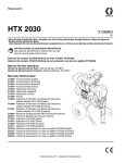
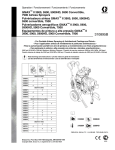
Component Identification - Sprayer / 䚽Ӌ䕽䅹⍗ᴏ
Component Identification - Sprayer / 䚽Ӌ䕽䅹⍗ᴏ
Top Coat Kit / 䴷ⓛ⋊䜢Ӌࣚ
8
1
2
3
9
10
8
7
4
5
11
ti13634a
6
English
313483A
Ђ᭜
1
ON/OFF Switch
䗯 ᮂᓕ݈
2
Prime Switch
(used with Base Coat Pump)
เ᭮ᓕ݈
ϣᑪ㡇ⓛ⋊䜢⫽
3
Pump Control
⋊ࠋఽ
4
Heavy Texture Material Hose
(used with Base Coat Pump)
傭㉭ᑻ㒎⧛⍗᭮䕄ㅶ
ϣᑪ㡇ⓛ⋊䜢⫽
5
Applicator Switch
⍗ఽᓕ݈
(used with Base Coat Pump--on Hose 5) ϣᑪ㡇ⓛ⋊䜢⫽ͼ䕄ㅶ ϟ
6
Applicator (Base Coat)
⍗ఽ ᑪ㡇ⓛ
7
Pump (Base Coat)
⋊ ᑪ㡇ⓛ
8
Drain / Pressure Relief Valve
⊙ॠ䯕
9
Pump (Top Coat)
⋊ 䴷ⓛ
10
Spray Gun (Top Coat)
ᵿ 䴷ⓛ
11
Paint/Texture Material Hose
(used with Top Coat Pump)
ⓛ᭮Ϳ㒎⧛⍗᭮䕄ㅶ
ϣ䴷ⓛ⋊䜢⫽
11
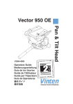
Component Identification - Base Coat Applicator / 䚽Ӌ䕽䅹ᑪ㡇ⓛ⍗ఽ
Component Identification - Base Coat Applicator /
䚽Ӌ䕽䅹ᑪ㡇ⓛ⍗ఽ
8
1
7
9
2
10
3
6
4
5
ti13635a
English
12
Ђ᭜
1
Applicator
⍗ఽ
2
Air Hose Adapter and Air Adjustment Valve
く⇩䕄ㅶ༉く⇩䇘㡗䯕
3
Airless Filter or Air Passage Plug
᮵⇩䖜Ⓓఽく⇩䗯䘨ᦧำ
4
Filter Support
䖜Ⓓఽᬄ᷆
5
Airless Spray Assembly
᮵⇩⍗㒙Ӌ
6
Airless Spray Tip
᮵⇩ఉ
7
Air nozzle, 4 mm, 6mm, 8mm, 10mm
く⇩ఉ PPPPPPPP
8
Air Nozzle Cleaner
く⇩ఉ⏚⋖ఽ
9
Cleaning Brush
⏚⋬ࠌ
10
Cleaning Ball
⏚⋬⧘
313483A
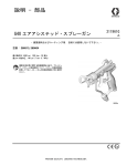
Operation / ᪢Ա
Operation / ᪢Ա
Pressure Relief Procedure / ⊙ॠ℺偹
Applicator (Base Coat Pump) / ⍗ఽ ᑪ㡇ⓛ⋊
ti6208b
English
1. Turn engine OFF.
2. Turn on/off switch OFF 3. Turn drain valve down
to DRAIN position.
and turn pressure conFluid from drain valve
trol knob fully countercan splash in eyes or
clockwise.
skin and cause serious
injury. Keep hands
clear of pressure relief
valve and always wear
safety glasses.
NOTE: If you suspect
spray tip or hose is completely clogged or that
pressure has not been fully
relieved after following the
previous steps, cover the
connection at end of hose
with a heavy rag and very
slowly loosen connection.
Ђ᭜
݈䯂দࡽᴏȢ
313483A
݈ᮂ䗯 ᮂᓕ݈ͼᑋᇛ ᇛ⊙ॠ䯕০Ϡᮠ䕁㟈⊙ ⊽䞟Ίབྷᵱᗕ⭦ఉ䕄
ॠࡰࠋᮠ䪃䗛ᯋ䩝ᮠ
ॠԢ㕃Ȣң⊙ॠ䯕⌖ߏ ㅶᅡܽชำᅡ៥ࠢ䗅
ࠅᑪȢ
ⱙ⌖Ԩӯܺⴑ℺ ⲃݚ偹ৣᗕ⭦ॠࡰᅡܽ䞟
ᬓᥞͼৄ⫽ϕബ९ᢎᏘⲫ
㙹ϟͼᇑ㟉Ϻ䞢ⱙᤴ
ӹȢডᠠ㽖䙔ᓕ⊙ॠ䯕 Ԥ䕄ㅶᴀツⱙ༉ͼ✋ৣ
ᵖЏ㓨അᵓᓕ༉Ȣ
ᑋྠ㒝᠉ϟ䰇䬱Ȣ
13
Operation / ᪢Ա
Pressure Relief Procedure / ⊙ॠ℺偹
Spray Gun (Top Coat Pump) / ᵿ 䴷ⓛ⋊
ti13050a
ti13131a
ti13130a
ti13128a
ti10796b
ti13130a
ti6208b
English
1. Lock gun trigger
safety and turn
engine OFF.
2. Turn on/off switch 3. Unlock trigger
safety. Hold
to OFF and turn
metal part of gun
pressure control
firmly to side of
knob fully coungrounded metal
terclockwise.
pail and trigger
gun to relieve
pressure.
4. Lock gun trigger
safety. Open
pressure drain
valve. Leave
valve open until
ready to spray
again.
NOTE: If you suspect that the spray
tip or hose is completely clogged, or
that pressure has
not been fully
relieved after following the previous
steps, VERY
SLOWLY loosen the
tip guard retaining
nut or hose end coupling to relieve pressure gradually, then
loosen completely.
Then clear tip or
hose.
݈ᮂ䗯 ᮂᓕ
݈ͼᑋᇛॠࡰ
ࠋᮠ䪃䗛ᯋ䩝ᮠ
ࠅᑪȢ
䫖ϟᵿᡈᴏⱙ
ᅞܽ䫕Ȣᠨᓕ⊙
ॠ䯕Ȣޛໜݢ
⍗Рࠢ䅾䯕䮽
ϕⳉᓕⴕȢ
⊽䞟Ίབྷᵱᗕ⭦ఉ
䕄ㅶᅡܽชำ
ᅡ៥ࠢ䗅℺偹ৣᗕ⭦
ॠࡰᅡܽ䞟ᬓᥞͼ
ᑩᵖЏ㓨അᵓᓕ
ఉ㔾ⱙᅯ㶏↢
䕄ㅶツ䚽ⱙ༉ͼՔ
ॠࡰ䗥⏥䞟ᬓᥞͼ✋
ৣݢᅡܽ
ᵓᓕȢ✋ৣ⏚⧛ఉ
䕄ㅶȢ
Ђ᭜
䫖ϟᵿᡈᴏⱙ
ᅞܽ䫕ͼ݈䯂দ
ࡽᴏȢ
14
ᓕᡈᴏⱙᅞܽ
䫕Ȣᇛᵿⱙ䞦
ሳ䚽ߛ㋼㋼䴵
അ䞦ሳṋⱙռ
䖎ͼ✋ৣᠸࡽ
ᵿᡈᴏҺ֔䞟ᬓ
ॠࡰȢ
313483A
Operation / ᪢Ա
Start Engine / 䍌ࡽদࡽᴏ
ti5249a
ti5250a
ti3315a
ti5248a
English
1. Move fuel valve to
OPEN.
2. Move choke to
CLOSED.
3. Set throttle to FAST.
4. Set engine switch to
ON.
ᇛ䰐亣䮽ࠅ݈䯂
Ԣ㕃Ȣ
ᇛ㡗⌖䯕䆓ᗀ䗴ḸȢ
ᇛদࡽᴏᓕ݈㕃ѣ䗯
Ԣ㕃Ȣ
Ђ᭜
ᇛ➘⊎䯕ࠅᠨᓕ
Ԣ㕃Ȣ
313483A
15
Operation / ᪢Ա
ti5263a
ti5264a
ti5251a
English
5. Pull starter rope.
6. After engine starts,
move choke to OPEN.
7. Set throttle to desired
setting.
দࡽᴏ䍌ࡽৣͼᇛ䰐亣
䮽ࠅᠨᓕԢ㕃Ȣ
ᇛ㡗⌖䯕䆓᠕᳴ᳰⱙ
Ԣ㕃Ȣ
Ђ᭜
ᢞ䍌ࡽ㓈Ȣ
16
313483A
Operation / ᪢Ա
Setup / 䆓㕃
ti13899a
ti13639a
ti4118a
English
1. Fill mixing pail with
pre-mixed texture material.
2. Connect material hose to pump outlet.
Add approximately 10%
water to texture mix or
per material manufacturer instructions. Mix
thoroughly.
Material and Sprayer Preparation
NOTE: A dry material hose can extract
water from the material and lead to a
plugged hose. If the inside of the hose
is dry, pump water through it before
pumping texture material.
Cementicious and other curing materials can harden within the drain valve
while spraying. At least once per hour
stop spraying and open the drain valve
to flush out the older material.
Ђ᭜
ᇛ乙⏌ܝঢ়དྷⱙ㒎⧛⍗᭮ ᇛ᭮ㅶ䖳㟈⋊ߏসȢ
⏌ܺקঢ়ṋݚȢ
০㒎⧛⍗᭮⏌ঢ়⎇Ђࡵ
ܺ㑻ⱙ∉ͼḎ
⍗᭮⫴Ѽॗᆋⱙ䇉ᯣ
⏐ࡵȢᕐᑪ⏌ঢ়Ȣ
⍗᭮ট⍗ᴏⱙޛໜ
⊽䞟Ίᑇⱙ᭮ㅶӯң⍗᭮Ђ∉ᑋᇑ㟉
䕄ㅶชำȢབྷᵱ䕄ㅶݚຖᑇ➺ͼ⋊䗖
㒎⧛⍗᭮Рࠢ㽖⫽ܝᢒ∉Ȣ
∉⊺ාᅘ㛒࣫ⱙ⍗᭮ӯ⍗᳴
䯉⊙ॠ䯕ݚ࣫Ȣᑩ㟈ᇦ↤ᇤᯋرℷ
⍗ϕͼᑋᠨᓕ⊙ॠ䯕Һߏއ䕘ᮼⱙ
⍗᭮Ȣ
NOTICE
DO NOT USE MATERIALS THAT
CURE RAPIDLY! Materials with a
fast curing time could plug the pump,
hose, gun, or applicator.
⊽ᛤ
Ϣ㽖Ք⫽ᗀ䗴࣫ⱙ⍗᭮ͱᗀ䗴࣫
ⱙ⍗᭮ৄ㛒ӯชำ⋊ȡ䕄ㅶȡᵿ
⍗ఽȢ
313483A
17
Operation / ᪢Ա
ti13652a
ti13640a
ti13633a
English
3. Pour mixed material
into supply pail under
sprayer.
4. Place pump suction
tube into mixed material.
Prime Pump
1. Start gasoline engine
and adjust speed to
half throttle. Turn drain
valve to DRAIN.
2. Place material hose
outlet over supply pail.
ᇛ⋊᭮ㅶᬓܺᏇ⏌ঢ়
⍗᭮ЂȢ
㒮⋊เ᭮
䍌ࡽ≒⊎দࡽᴏᑋ䇘㡗
䗴ᑻ㟈ट⊎䮽Ȣᇛ⊙ॠ
䯕ᮠ䕁㟈⊙ॠԢ㕃Ȣ
ᇛ᭮ㅶߏসᬓհ᭮ṋ
ϟᮎȢ
Ђ᭜
ᇛᏇ⏌ঢ়⍗᭮ܺק⍗
ᴏϠ䴷ⱙհ᭮ṋݚȢ
18
313483A
Operation / ᪢Ա
ti13900a
ti11930a
ti13649a
ti10796b
ti10795b
ti13636a
English
3. Top Coat Pump: 4. Rotate pressure
control knob 1/4
Turn on/off switch
turn. Run pump
ON.
until a steady
stream of mateBase Coat
rial flows from
Pump:
drain valve.
Turn Prime
switch ON, or
activate applicator switch on
material hose.
5. Turn on/off switch 6. Turn on/off switch 7. Connect applicator to material
ON, and run
OFF and turn
hose.
pump until a
drain valve knob
steady stream of
to SPRAY.
material flows
from material
hose. Turn on/off
switch to OFF
and turn drain
valve knob to
DRAIN.
Ђ᭜
䴷ⓛ⋊Ί䗯䗯
ᮂᓕ݈Ȣ
ᑪ㡇ⓛ⋊Ί䗯
เ᭮ᓕ݈ͼ
ࡽ᭮ㅶϟⱙ⍗
ఽᓕ݈Ȣ
313483A
ᇛॠࡰࠋᮠ䪃
ᮠ䕁ೝȢ䅾
⋊䖥䕁ͼⳉࠅ⍗
᭮ң⊙ॠ䯕Ђᑈ
〈അ⌖ߏȢ
݈ᮂ䗯 ᮂᓕ
݈ͼ✋ৣᇛ⊙ॠ
䯕ᮠ䪃ᮠ䕁㟈
⍗Ԣ㕃Ȣ
䗯䗯 ᮂᓕ
݈ͼ✋ৣ䅾⋊䖥
䕁ͼⳉࠅ⍗᭮ң
᭮ㅶЂᑈ〈അ⌖
ߏȢ݈ᮂ䗯 ᮂ
ᓕ݈ͼ✋ৣᇛ⊙
ॠ䯕ᮠ䪃ᮠ䕁㟈
⊙ॠԢ㕃Ȣ
ᇛ⍗ఽ䖳ࠅ
᭮ㅶϟȢ
19
Operation / ᪢Ա
ti13651a
ti13648a
ti13650a
ti8794a
English
Spray Without Air
1. Install filter and tip
extension.
2. Insert metal seat and
OneSeal. Insert
Switch Tip. Screw
assembly onto applicator.
3. Turn drain valve to
SPRAY, and turn
on/off switch to ON.
Turn pump control
clockwise until
desired material delivery rate is achieved.
4. Spray test pattern.
Aim applicator at floor.
Turn applicator switch
ON and move applicator to spray surface.
ᦧܺ䞦ሳᑼ
2QH6HDOȢᦧܺ
6ZLWFK7LSఉȢ
ᇛ㒙㺚Ӌᮠࠅ
⍗ఽϟȢ
ᇛ⊙ॠ䯕ᮠ䕁㟈⍗
Ԣ㕃ͼ✋ৣ䗯䗯 ᮂᓕ݈Ȣ乏ᯋ䩝ᮠ䕁
⋊ࠋఽͼⳉ㟈䖓ࠅ
᠕䳕ⱙ⍗᭮䕨䗖䗴ᑻȢ
⍗䆪偡ൠȢᇛ
⍗ఽᇎޛഅ䴷Ȣ䗯
⍗ఽᓕ݈ᑋ⿐ࡽ
⍗ఽҺ⍗㸽䴷Ȣ
Ђ᭜
᮵く⇩⍗
㺚ϟ䖜Ⓓఽఉࡵ
䭔ӋȢ
20
313483A
Operation / ᪢Ա
ti11715a
ti11714a
English
Spray Without Air - Clear Clog
1. Rotate SwitchTip to
Clear position. Aim
applicator at floor and
turn pump ON. When
clog clears, turn pump
OFF.
2. Rotate SwitchTip to
Spray position. Turn
pump ON. Spray test
pattern.
Ђ᭜
᮵く⇩⍗ͽ⏚䰹ชำ⠾
ᇛ6ZLWFK7LSఉᮠ
ࠅ⏚⧛Ԣ㕃Ȣᇛ⍗
ఽᇎޛഅ䴷ᑋ䗯⋊Ȣ
⏚䰹ћชำ⠾Рৣͼ
݈䯂⋊Ȣ
313483A
ᇛ6ZLWFK7LSఉᮠ
ࠅ⍗Ԣ㕃Ȣ䗯⋊Ȣ
⍗䆪偡ൠȢ
21
Operation / ᪢Ա
ti13637a
ti10796b
ti13647a
ti4650a
ti13636a
English
Spray With Air (Base Coat
Applicator)
1. Prepare material, page 17. Place
material hose in supply pail.
2. Turn on/off switch
OFF.
3. Remove cap
before installing
air line.
4. Turn air valve OFF.
Connect applicator to
material hose and air
hose. Air supply minimum requirement is
3.5 bar and 350
l/min.
Ђ᭜
く⇩⍗ ᑪ㡇ⓛ⍗ఽ
བྷ乊᠕䗅ޛໜ⍗᭮Ȣᇛ᭮ㅶ
ᬓܺհ᭮ṋݚȢ
݈ᮂ䗯 ᮂᓕ݈Ȣ ᅞ㺚⇩䏄Рࠢ㽖् ݈䯂く⇩䯕Ȣᇛ᭮
ϠᐒᄥȢ
ㅶく⇩䕄ㅶ䖳
ࠅ⍗ఽϟȢ᳕ԣհ
⇩㽖∗ЏEDUͼ
OPLQȢ
NOTICE
DO NOT USE MATERIALS THAT
CURE RAPIDLY! Materials with a
fast curing time could plug the pump
hose, gun, or applicator.
⊽ᛤ
Ϣ㽖Ք⫽ᗀ䗴࣫ⱙ⍗᭮ͱᗀ䗴࣫
ⱙ⍗᭮ৄ㛒ӯชำ⋊ȡ䕄ㅶȡᵿ
⍗ఽȢ
22
313483A
Operation / ᪢Ա
4 mm
6 mm
8 mm
ti8794a
10 mm
ti13646a
ti11798a
ti10795b
ti13641a
English
5. Turn on/off switch 6. Hold applicator
ON.
over material pail
and turn pump
ON using applicator switch on
hose.
7. Turn pump control clockwise
until desired
material delivery
rate is achieved.
8. Spray test pattern. Aim applicator at floor.
Turn air valve
ON. Move applicator to spray
surface.
9. Adjust air valve
and/or select
alternative nozzle size (4 10mm) for
desired finish.
乏ᯋ䩝ᮠ䕁⋊
ࠋఽͼⳉ㟈䖓ࠅ
᠕䳕ⱙ⍗᭮䕨䗖
䗴ᑻȢ
⍗䆪偡ൠȢ
ᇛ⍗ఽᇎޛ
അ䴷Ȣᠨᓕく
⇩䯕Ȣ⿐ࡽ⍗
ఽҺ⍗㸽䴷Ȣ
䇘㡗く⇩䯕ᑋͿ
䗞ᢾⱙ
ఉሏᇍ
PPͼҺ㦌ᕬ
᠕᳴ᳰⱙ㒝佅Ȣ
Ђ᭜
䗯䗯 ᮂᓕ݈Ȣ ᇛ⍗ఽᦶ᭮
ṋϟᮎͼ✋ৣ⫽
䕄ㅶϟⱙ⍗ఽ
ᓕ݈䗯⋊Ȣ
313483A
23
Operation / ᪢Ա
ti5799a
safety
ON
SwitchTip
ti5799a
Seat
heavy
edges
ti5823a
ti5824a
ti5800a
One seal
ti5801a
English
Spray Gun (Top Coat
Pump)
1. Lock gun trigger
safety. Insert seat and
OneSeal™. Insert
SwitchTip.
2. Screw assembly onto
gun. Hand tighten.
3. Trigger gun and spray
test pattern. Slowly
adjust pressure to
eliminate heavy
edges. Use smaller tip
size if pressure
adjustment can not
eliminate heavy
edges.
4. Hold gun perpendicular, 10-12 in. (25-30
cm) from surface.
Spray back and forth.
Use strokes overlapped by 50%. Start
gun movement before
triggering gun and
release trigger before
stopping gun movement.
ᇛ㒙㺚ӋᮠࠅᵿϟȢ
⫽ᠠᢼ㋼Ȣ
ᠸࡽᵿᡈᴏᑋ⍗
䆪偡ൠȢ㓨䇘ᭉ
ॠࡰҺ⍝䰹९䖎Ȣབྷ
ᵱ᮵⊪䗯䖜䇘ᭉॠࡰ
⍝䰹९䖎ͼৄ䞜⫽ሏ
ᇍ䕘ᇤⱙఉȢ
ൗⳉᦶԤᵿͼՔ
䎲⾐㺀㸽䴷
㣆ᇍ
FPȢ䖰㸡
ᴺಳ⍗Ȣ䅾䘨᳞
ⱙᨂȢ㽖ᠸ
ࡽᡈᴏРࠢሆᓕྠ⿐
ࡽᵿͼ㗡ᡈᴏ䞟
ᬓРৣᠢرℷᵿⱙ
⿐ࡽȢ
Ђ᭜
ᵿ 䴷ⓛ⋊
䫖ϟᵿᡈᴏⱙᅞܽ
䫕Ȣᦧܺ䯕ᑼ
2QH6HDO™Ȣᦧܺ
6ZLWFK7LSఉȢ
24
313483A
Operation / ᪢Ա
Cleanup / ⏚⋬
ti10796b
ti13645a
ti13644a
English
1. Turn on/off switch OFF. 2. Perform Pressure
Relief procedure,
page 13.
3. Place pump in pail of
clean water.
4. Shut OFF air if spraying with air. Remove
applicator from material and air hoses.
ᇛ⋊ᬓܺ⏚∉ṋЂȢ
བྷᵱᰄく⇩⍗ͼ݈߮
䯂く⇩Ȣᮂᓕ⍗ఽϣ
᭮ㅶটく⇩䕄ㅶⱙ䖳
Ȣ
Ђ᭜
݈ᮂ䗯 ᮂᓕ݈Ȣ
313483A
ᣞ✼乊ⱙ⊙
⊙ॠ℺
偹᪢ԱȢ
25
Operation / ᪢Ա
ti13643a
ti13640a
ti13639a
ti10795b
ti13638a
English
5. Disconnect material
6. Insert wet cleaning ball
hose from pump outlet.
into hose (Base Coat
Only). Connect material hose to pump outlet.
7. Hold material hose
over waste pail.
8. Turn on/off switch ON.
Base Coat Pump:
Turn on/off switch ON
and prime switch ON,
or applicator switch on
material hose.
Ђ᭜
ң⋊ߏসᮂᓕ᭮ㅶⱙ
䖳Ȣ
26
ᇛⱙ⏚⋬⧘ᦧܺ䕄
ㅶ ݚҚ䰥ᑪ㡇ⓛȢ
ᇛ᭮ㅶ䖳㟈⋊ߏসȢ
ᇛ᭮ㅶᦶᑴ⎇ṋ
ϟᮎȢ
䗯䗯 ᮂᓕ݈Ȣ
ᑪ㡇ⓛ⋊Ί䗯䗯 ᮂᓕ݈เ᭮ᓕ݈ͼ
䗯᭮ㅶϟⱙ⍗
ఽᓕ݈Ȣ
313483A
Operation / ᪢Ա
ti10796b
ti13636a
ti10795b
ti13633a
ti4551c
English
9. Run pump until cleaning ball exits material
hose. Save cleaning
ball (Base Coat Only).
10. Turn on/off switch OFF
and turn prime valve to
DRAIN. Clean outside
of pump and suction
tube with brush and
water.
11. Connect applicator to
material hose. Close
drain valve.
12. Turn on/off ON.
݈ᮂ䗯 ᮂᓕ݈ͼ✋ৣ
ᇛเ᭮䯕ᮠ䕁㟈⊙ॠԢ
㕃Ȣ⫽ࠌᄥ∉⏚⋖⋊
ট᭮ㅶⱙ㸽䴷Ȣ
ᇛ⍗ఽ䖳ࠅ᭮
ㅶϟȢ݈䯂⊙ॠ䯕Ȣ
䗯䗯 ᮂᓕ݈Ȣ
Base Coat Pump:
Turn on/off switch ON
and prime switch ON,
or applicator switch on
material hose.
Ђ᭜
䅾⋊䖥䕁ͼⳉࠅ⏚
⋬⧘ң᭮ㅶЂᥞߏȢ
ֲㅶདྷ⏚⋬⧘
Қ䰥ᑪ㡇ⓛȢ
313483A
ᑪ㡇ⓛ⋊Ί䗯䗯 ᮂᓕ݈เ᭮ᓕ݈ͼ
䗯᭮ㅶϟⱙ⍗
ఽᓕ݈Ȣ
27
Operation / ᪢Ա
ti10796b
ti13633a
ti13641a
ti13839a
English
13. Run pump until clean
water flows from applicator.
14. Add additional water
and repeat steps 12 13 if necessary.
15. Open drain valve and
turn prime switch ON
to flush valve.
16. Turn on/off switch OFF.
Ђ᭜
䅾⋊䖥䕁ͼⳉࠅң⍗
ఽЂ⌖ߏ⏚∉Ȣ
28
བྷᵱ᳞ᖚ㽖ͼৄ⏐ࡵ ᠨᓕ⊙ॠ䯕ᑋ䗯เ᭮
ⱙ∉ͼ✋ৣ䞢℺偹
ᓕ݈ͼҺ⊙⋬އॠ䯕Ȣ
Ȣ
݈ᮂ䗯 ᮂᓕ݈Ȣ
313483A
Operation / ᪢Ա
ti13642a
ti11810a
ti11811a
English
17. Remove and thoroughly clean
applicator, spray tips and guard
with brush.
18. Clean hardened material from
applicator nozzles with air nozzle
cleaner.
NOTICE
Do not use air nozzle cleaner to clean
applicator check valve or airless spray
tip. Damage will occur.
Remove air check valve from applicator to clean hardened material from
interior of applicator.
Ђ᭜
्Ϡᑋ⫽ࠌᄥᕐᑪ⏚⋬⍗ఽȡ
ఉট㔾Ȣ
⫽く⇩ఉ⏚⋖ఽ⏚䰹⍗ఽ
ఉϟⱙᏇ⹁࣫ⱙ⍗᭮Ȣ
⊽ᛤ
Ϣ㽖Ք⫽く⇩ఉ⏚⋖ఽᴺ⏚䰹⍗ఽℷ
ಳ䯕᮵⇩ఉȢ৻߮ӯদ⫴ᤴതȢ
㢺䳕⏚䰹⍗ఽⱙݚᏇ⹁࣫ⱙ⍗᭮ͼ㽖ң
⍗ఽϟ्Ϡく⇩ℷಳ䯕Ȣ
313483A
29
Operation / ᪢Ա
Digital Tracking System (DTS) / ᭅᄬ䎴䏿㋐㒴
ti5802a
ti5804a
English
Main Menu
Close cover when spraying to protect display.
1. Perform Startup steps
1 - 2.
•
Open drain valve
•
Turn pump control
counterclockwise to
lowest setting
•
Set applicator switch to
OFF
2. Start Engine, page
15. Display will
momentarily show
which pump is installed
(Base or Top) and then
Flow 1, 2, or 3 (if Base
Coat pump is
installed). Pressure
display appears, then
dashes appear when
pressure is less than
60 psi (4 bar, 0.4 MPa).
NOTE: Information other
than pressure cannot be
accessed if applicator
switch is ON. And, if system pressure is greater
than 200 psi (14 bar, 1.4
MPa), the display will revert
back to pressure after 3
seconds.
䍌ࡽদࡽᴏͼ㾖
乊Ȣᰓ⼏ぬসӯⷂ᱗ᰓ
⼏᠕ᅞ㺚ⱙᰄિ⾢⋊
%DVH Ϋᑪ㡇ⓛέ
7RS Ϋ䴷ⓛέͼ✋ৣ
ᰓ⼏⌖䞤ȡ
བྷᵱ᠕ᅞ㺚ⱙᰄᑪ
ᑪ
㡇ⓛ⋊Ȣ✋ৣߏ⦅
ॠࡰᰓ⼏ͼᔨॠࡰ
ᇤѣ SVLEDU
03D ᯋͼӯᰓ
⼏ߏ⸉ᡭৌȢ
⊽䞟Ίབྷᵱ⍗ఽᓕ݈
໙ѣ䗯Ԣ㕃ͼ߮ি㛒
ᰓ⼏ॠࡰͼϢᰓ⼏ᅘ
ֶᙄȢ㗡ϩͼབྷᵱ㋐㒴ॠ
ࡰ䍚䖜 SVLEDU
03Dͼӯ⾧䩴ৣ
䖩ಳࠅॠࡰᰓ⼏Ȣ
Ђ᭜
А㦱प
䍌ࡽϕ㡗ⱙ℺偹
䖰㸡䍌
Ȣ
⍗ᯋ㽖݈ϟⲫᄥͼҺֲ
ᰓ⼏ぬȢ
• ᠨᓕ⊙ॠ䯕
30
•
ᇛ⋊ࠋఽ䗛ᯋ䩝ᮠࠅ
᳕ԣ䆓ᅯؑ
•
ᇛ⍗ఽᓕ݈㕃ѣ݈ᮂ
Ԣ㕃
313483A
Operation / ᪢Ա
psi
bar
psi
MPa
ti13761a
ti13762a
ti6225a
ti13760a
English
3. Short press DTS
button to display
installed pump.
4. Short press DTS button to move to Engine
RPM.
5. Short press DTS button to return to Pressure.
To Change Pressure Units:
Press and hold (8 seconds) DTS
button to change pressure unit
(psi, bar, MPa).
Continue to press DTS button to
cycle from psi to bar to MPa.
Release DTS button to select
units.
Ђ᭜
ⷂ᱗ᣞϠ'76ᣞ
䬃ͼҺᰓ⼏᠕ᅞ
㺚ⱙ⋊Ȣ
ⷂ᱗ᣞϠ'76ᣞ䬃ͼ
Һᰓ⼏দࡽᴏ䕁䗴Ȣ
ⷂ᱗ᣞϠ'76ᣞ䬃ͼ
Һ䖩ಳࠅॠࡰᰓ⼏Ȣ
㢺㽖ᬎভॠࡰपԢΊᣞϠᑋᣞԤ
'76ᣞ䬃 ⾧䩴ͼৄᬎভॠ
ࡰपԢ SVLȡEDUȡ03DȢ
㒼㓂ᣞϠ'76ᣞ䬃ӯᕿ⦄ᰓ⼏
SVLȡEDUȡ03DȢ䞟ᬓ'76ᣞ䬃
䗞ᢾपԢȢ
313483A
31
Operation / ᪢Ա
Secondary Menu - Stored Data Mode / ѡ㑼㦱प᠕ᄭⱙٽᭅῶᓤ
ti5812a
ti13764a
ti6213a
English
•
Open drain valve
•
Turn pump control
counterclockwise to
lowest setting
•
Set applicator switch to
OFF
1. Start Engine, page 15.
Pressure display
appears.
2. Press and hold DTS
button and turn applicator switch ON.
䍌ࡽদࡽᴏͼ㾖
乊Ȣߏ⦅ॠࡰᰓ⼏Ȣ
ᣞϠᑋᣞԤ'76ᣞ䬃ͼ ⒯ࡽᰓ⼏ Ć6(5,$/
✋ৣ䗯⍗ఽᓕ݈Ȣ
180ć ᑋᰓ⼏ߏϕϿ
ͽԢᭅᄬⱙ㋐
߬ৌȢ
3. SERIAL NUM scrolls
through display and a
3 to 5-digit serial number displays.
Ђ᭜
•
ᠨᓕ⊙ॠ䯕Ȣ
•
ᇛ⋊ࠋఽ䗛ᯋ䩝ᮠࠅ
᳕ԣ䆓ᅯؑ
•
ᇛ⍗ఽᓕ݈㕃ѣ݈ᮂ
Ԣ㕃
32
313483A
Operation / ᪢Ա
ti6215a
ti13786a
ti13787a
ti6220a
English
4. Short press DTS button and date code displays.
5. Short press DTS button and part number
displays.
6. Short press DTS button and Base Coat
hours displays.
Short press DTS button and Top Coat
hours display.
Short press DTS button and Engine hours
display.
7. Short press DTS button and LAST ERROR
scrolls through display
followed by stored
error message and
error code. This information cycles repeatedly until cleared.
See page 35 for error
code explanations.
Ђ᭜
ⷂ᱗ᣞϠ'76ᣞ䬃ͼ
ैᰓ⼏ߏᮺ᳴ҸⷖȢ
ⷂ᱗ᣞϠ'76ᣞ䬃ͼ
ैᰓ⼏ߏ䚽ӋৌȢ
ⷂ᱗ᣞϠ'76ᣞ䬃ͼ
ैᰓ⼏ߏᑪ㡇ⓛᇤ
ᯋᭅȢ
ⷂ᱗ᣞϠ'76ᣞ䬃ͼ
ैᰓ⼏ߏ䴷ⓛᇤᯋᭅȢ
ⷂ᱗ᣞϠ'76ᣞ䬃ͼ
ैᰓ⼏ߏদࡽᴏᇤ
ᯋᭅȢ
313483A
ⷂ᱗ᣞϠ'76ᣞ䬃ͼ
ै⒯ࡽᰓ⼏ Ć/$67
(5525ćͼᑋ䱤ৣᰓ⼏
ߏ᠕ᄭⱙٽ䫮䇄⍝ᙄ
䫮䇄ҸⷖȢℹֶᙄӯঢ
ᕿ⦄ᰓ⼏ͼⳉ㟈ᇛ
⏚䰹ЏℷȢ
᳞݈䫮䇄Ҹⷖⱙ㾸䞟ͼ
䇌গ㾖乊Ȣ
33
Operation / ᪢Ա
ti13788a
ti6218a
ti5822a
English
8. Press and hold DTS
button until CLEAR
ERROR NO ERROR
CODE scrolls through
the display and error
code E=00 displays.
9. Short press DTS button again and SOFTWARE REV scrolls
through display followed by revision level
(for example 10102).
10. Short press to return to
step 3. Turn on/off
switch OFF at any time
to exit stored data
mode.
Ђ᭜
ᣞϠᑋᣞԤ'76ᣞ䬃ͼ ⷂݢ᱗ᣞϠ'76
ᣞ䬃ͼै⒯ࡽᰓ⼏
ⳉ㟈⒯ࡽᰓ⼏ߏ
Ć62)7:$5(5(9ćͼ
Ć&/($5(552512
ᑋ䱤ৣᰓ⼏ߏ׃䅷ৌ
(5525&2'(ćͼ㗡ϩ
ՠབྷΊȢ
䫮䇄Ҹⷖᰓ⼏Џ
Ć( ćȢ
34
ⷂ᱗ᣞϠҺ䖩ಳࠅ
℺ȢӐԪᯋ݈ᮂ䗯 ᮂᓕ݈ͼैৄ䗕ߏ Ć
᠕ᄭⱙٽᭅ ć
ῶᓤȢ
313483A
Operation / ᪢Ա
Digital Display Messages
DISPLAY*
No Display
SPRAYER OPERATION
INDICATION
ACTION
Sprayer may be pressurized
Loss of power or display
not connected
Check power source. Relieve pressure before
repair or disassembly. Verify display is
connected.
Sprayer may be pressurized
Pressure less than
60 psi (4 bar, 0.4 MPa)
Increase pressure as needed
BASE
or
TOP
Displays installed pump when
engine is started
Normal operation
Spray
FLOW 1
FLOW 2
or
FLOW 3
Displays flow control setting in
Base Coat mode when pump
control setting is changed
Normal operation
(with Base Coat pump)
Spray
Sprayer is pressurized. Power
is applied. (Pressure varies
with tip size and pressure
control setting.)
Normal operation
Spray
Top Coat Only: Sprayer
stops. Engine is running.
Pressure greater than
4500 psi (310 bar, 31
MPa)
1
Check fluid path for clogs.
2
Use Graco paint hose, 3/8 in. x 50 ft
minimum. Smaller hose or metal braid hose
may result in pressure spikes.
3
Replace transducer if fluid path is not
clogged and proper hose is used.
1
Check transducer connection.
2
Disconnect and reconnect transducer plug
to ensure good connection with control
board socket.
3
Open prime valve. Replace sprayer
transducer with known good transducer and
run sprayer. Replace transducer if sprayer
runs or control board if sprayer does not run.
1
Check wiring connections.
2
Measure: 1.7 + 0.2: across clutch field at
70°F.
3
Replace clutch field assembly.
1
Open prime valve and gun.
2
Verify no flow obstructions. Use Graco
texture hoses 3/4 in. x 50 ft minimum.
3
Replace transducer if fluid path is not
clogged and proper hose is used.
ti6314a
psi
bar
MPa
ti6315a
ti6316a
Sprayer stops. Engine is
running.
Pressure transducer
faulty, bad connection or
broken wire
ti6317a
Sprayer stops. Engine is
running.
High clutch current
ti6318a
Base Coat Only: Sprayer
stops. Engine is running.
Pressure greater than
1000 psi (69 bar, 6.9
MPa)
* Error codes also appear on control board as a blinking red
LED. LED is an alternate to digital messages.
1
2
Remove two screws (71) and swing down cover (130).
Start engine. Blink count is the same as error code(E=0X).
After a fault, follow these steps to restart sprayer:
1 Correct fault condition.
2 Turn sprayer OFF.
3 Turn sprayer ON.
(E02 and E07 errors will self-correct when system is reduced)
313483A
35
Operation / ᪢Ա
ᭅᄬᰓ⼏ֶᙄ
ᰓ⼏ ᮵ᰓ⼏
⍗ᴏ᪢Ա
ᣜ⼏
ᮒ
⍗ᴏৄ㛒Ꮗࡵॠ
ᮂ⬊ᰓ⼏ぬ䖳
ẕᶺ⬊⑥Ȣ⧛׃ᢛ्Рࠢ䞟ᬓॠࡰȢ
⹃䅹ᰓ⼏ぬᏇ䖳Ȣ
⍗ᴏৄ㛒Ꮗࡵॠ
ॠࡰᇤѣ
SVLEDU03D
Ḏ䳕㽖ࡵॠࡰ
%$6(
723
দࡽᴏ䍌ࡽৣᰓ⼏᠕ᅞ㺚ⱙ
⋊
ℸᐍ᪢Ա
⍗
)/2:
)/2:
)/2:
ᔨ⋊ࠋఽ䆓ᅯؑᬎভᯋͼᰓ
⼏ᑪ㡇ⓛῶᓤϠⱙ⌖䞤ࠋ䆓
ᅯؑȢ
ℸᐍ᪢Ա
ϣᑪ㡇ⓛ⋊䜢⫽
⍗
⍗ᴏᏇࡵॠȢ⬊⑥Ꮗ䗯Ȣ
ॠࡰؑ䱤ఉᇤॠࡰ
ࠋⱙ䆓㕃㗡᳞᠕ভ࣫Ȣ
ℸᐍ᪢Ա
⍗
Қ䰥䴷ⓛΊ⍗ᴏرᴏȢ
দࡽᴏℸᎺԱȢ
ॠࡰѣSVL
EDU03D
ẕᶺ⌖Ԩ䗯䏄ᰄ৻ชำȢ
Ք⫽*UDFR⍗᭮䕄ㅶͼ᳕ᇤ㾙ḑЏ㣆
ᇍ[㣆ሏȢ䕘ᇤⱙ䕄ㅶ䞦ሳ㓫㒜ㅶৄ
㛒ӯᓪ䍌ॠࡰᇫዅȢ
བྷᵱ⌖Ԩ䗯䏄ชำ㗡ϩ᠕⫽ⱙ䕄ㅶঢ়䗗ͼ
߮ᤷӵᛴఽȢ
ẕᶺӵᛴఽⱙ䖳Ȣ
ᮂᓕᑋ䞢ᮅ䖳ӵᛴఽᦧ༉Һֲ䆖ϣࠋᵔ
ᦧῒⱙ㡄དྷ䖳Ȣ
ᠨᓕเ᭮䯕Ȣ⫽Ꮗⶺདྷⱙӵᛴఽ᳔ᤷ⍗ᴏ
ⱙӵᛴఽͼᑋ䖥䕁⍗ᴏȢབྷᵱ⍗ᴏᎺ
Աͼ߮ᤷӵᛴఽབྷᵱ⍗ᴏϢᎺԱͼ
߮ᤷࠋᵔȢ
ẕᶺ㒔䖳Ȣ
⌠䞤Ί: ⾐ঢ়ఽ㒔㒙Ϲツ
⏾ᑻЏe)Ȣ
ᤷ⾐ঢ়ఽ㒔㒙㒙ӋȢ
ᠨᓕเ᭮䯕ᵿȢ
⹃䅹⌖Ԩ䗯䏄ชำȢՔ⫽*UDFR㒎⧛⍗᭮
䕄ㅶͼ᳕ᇤ㾙ḑЏ㣆ᇍ[㣆ሏȢ
བྷᵱ⌖Ԩ䗯䏄ชำ㗡ϩ᠕⫽ⱙ䕄ㅶঢ়䗗ͼ
߮ᤷӵᛴఽȢ
ti6314a
psi
bar
MPa
ti6315a
ti6316a
⍗ᴏرᴏȢদࡽᴏℸ
ᎺԱȢ
ॠࡰӵᛴఽᬚ䱱ͼ䖳᳞
䯃乭ᇑ㒔ᮂᓕ
ti6317a
⍗ᴏرᴏȢদࡽᴏℸ
ᎺԱȢ
⾐ঢ়ఽ⬊⌖䖜
ti6318a
Қ䰥ᑪ㡇ⓛΊ⍗ᴏرᴏȢ
দࡽᴏℸᎺԱȢ
ॠࡰѣ
SVLEDU
03D
ᬚ䱱Ҹⷖдߏ⦅ࠋᵔϟͼ⫽䮿⚖ⱙ㑷㡇/(' ᣜ⼏♄㸽
⼏Ȣ/('ᣜ⼏♄ᰄᭅᄬֶᙄⱙϕ⾢᳔Ҹ㸽⼏Ȣ
्ϠϿ㶏䩞 ᑋ㗐Ϡⲫᄥ Ȣ
䍌ࡽদࡽᴏȢ䮿⚖䅶ᭅؑҸ㸽ⳍᑩⱙᬚ䱱Ҹⷖ ( ;Ȣ
দ⫴ᬚ䱱ৣͼᣞ✼Ϡ䴷℺偹䞢ᮅ䍌ࡽ⍗ᴏΊ
㑵ℸᬚ䱱ᚚފȢ
݈䯂⍗ᴏȢ
ᠨᓕ⍗ᴏȢ
ᔨ㋐㒴ॠࡰ䰢ԣৣͼ((䫮䇄ӯ㞿ࡽ㑵ℸ
36
313483A
Maintenance / 㓉
Maintenance / 㓉
English
NOTICE
DAILY:
For detailed engine mainte- •
nance and specifications,
refer to separate Honda
•
Engines Owner’s Manual
(supplied).
Check engine oil level and fill
as necessary
AFTER FIRST 20 HOURS OF OPERATION
•
Check hose for wear and damage
•
Check that all hose fittings are
secure
•
Check gun safety for proper
operation
•
Check and fill the gas tank
•
Check level of TSL in displacement pump packing nut. Fill
nut, if necessary. Keep TSL in
nut to help prevent fluid buildup
on piston rod and premature
wear of packings and pump
corrosion.
Drain engine oil and refill with clean oil.
Reference Honda Engines Owner’s
Manual for correct oil viscosity.
Ђ᭜
⊽ᛤ
᳞݈দࡽᴏⱙ㓉㾙ḑ
ⱙ䆻㒛ᚚͼފ䇌গ㾖प⣁
ⱙᴁ⬅ +RQGDদࡽᴏ
⫽᠌ᠠ ݡᏇᦥհȢ
313483A
↤Ί
•
ẕᶺদࡽᴏⱙ⊎ԢͼৄḎ䳕
㽖⏐ࡵᴏ⊎
•
ẕᶺ䕄ㅶᰄ৻᳞⺽ᤴটᤴത
•
ẕᶺ᠕᳞䕄ㅶ༉ᰄ৻⠷
䖳
•
ẕᶺᵿⱙᅞܽ䫕ᰄ৻ℸᐍ
ᎺԱ
•
ẕᶺ≒⊎ㆆᑋࡵ⊎
•
ẕᶺ⌐ำ⋊ᆛᇖ㶏↢Ђⱙㅶ
ᆛᇖ⎇ 76/⎇ԢȢ㢺᳞ᖚ㽖
ৄᇛ⊽ⒶȢྠ㒝㶏↢Ђ⊽
Ⓐㅶᆛᇖ⎇ 76/᳞ࡾѣ䰇
ℷ⌐ำ᷆ϟ⎹⿄⌖Ԩȡᆛᇖ
䖜ᮾ⺽ᤴҺট⋊বࠅ㜥㱕
䖥㸡᳕߲ⱙᇤᯋРৣ
•
ᥧᥞᴏ⊎ͼ✋ৣ䞢ᮅࡵܺᑇⱙޕᴏ⊎Ȣ
᳞݈ℸ⹃ⱙᴏ⊎㉭ᑻͼ䇌গ㾖ᴁ⬅
+RQGDদࡽᴏ⫽᠌ᠠݡȢ
37
Maintenance / 㓉
English
WEEKLY
•
AFTER EACH 100
HOURS OF OPERATION
Remove engine air fil- •
ter cover and clean
element. Replace element if necessary. If
operating in an unusually dusty environment,
check filter daily and
replace (if necessary).
SPARK PLUG:
•
Change engine oil.
Reference Honda
Engines Owner’s Manual for correct oil viscosity.
Use only BPR6ES
(NGK) or W20EPR-U
(NIPPONDENSO)
plug. Gap plug to
0.028 to 0.031 in. (0.7
to 0.8 mm). Use spark
plug wrench when
installing and removing
plug.
Engine Oil Funnel:
•
Use the supplied
engine oil funnel when
draining oil.
Replacement elements
can be purchased from
your local Honda
dealer.
ti6200a
Ђ᭜
↤
•
्Ϡদࡽᴏⱙく⇩䖜
Ⓓఽ㔾ᑋ⏚⋖Ⓓ㢄Ȣ
㢺᳞ᖚ㽖ৄᤷⒹ㢄Ȣ
བྷᵱᎺԱ⦄๘ᓗᐍ
ᇭͼ㽖↤ẕᶺ䖜Ⓓ
ఽᑋ Ḏ䳕㽖
ѝҺᤷȢ
Ⓓ㢄᳔ᤷӋৄ০ᙽᔨഅ
ⱙᴁ⬅ +RQGD㒤䫕
ଛ䌂хȢ
↤䖥㸡ᇤᯋРৣ
•
ᤷᴏ⊎Ȣ᳞݈ℸ⹃ⱙ
ᴏ⊎㉭ᑻͼ䇌গ㾖ᴁ⬅
+RQGDদࡽᴏ⫽᠌
ᠠݡȢ
♀㢆ำΊ
•
ি㛒Ք⫽%35(6
1*.:(358
1,3321'(162♀㢆
ำȢ♀㢆ำᑩ⬮᳞
ͽ㣆ᇍ
ͽPP
ⱙ䯉䱮Ȣ㽖Ք⫽♀
㢆ำᡈᠠᅞ㺚ᢛ
्♀㢆ำȢ
ᴏ⊎ⓤ᭬Ί
•
ᬓ⊎ᯋͼ㽖Ք⫽᠕ᦥհ
ⱙᴏ⊎ⓤ᭬Ȣ
WLD
38
313483A
Troubleshooting
Troubleshooting
Problem
E=XX is displayed
Engine will not start
Engine operates, but displacement
pump does not operate
Cause
Solution
Fault condition exists
Engine switch is OFF
Engine is out of gasoline
Determine fault correction from table, page 35.
Turn engine switch ON
Refill gas tank. Honda Engines Owner's Manual.
Engine oil level is low
Try to start engine. Replenish oil, if necessary.
Honda Engines Owner's Manual.
Spark plug is disconnected or damaged Connect spark plug cable or replace spark plug
Cold engine
Use choke
Fuel shutoff lever is OFF
Move lever to ON position
Oil is seeping into combustion chamber Remove spark plug. Pull starter 3 to 4 times.
Clean or replace spark plug. Start engine.
Keep sprayer upright to avoid oil seepage
Error code displayed
Reference Pressure Control repair, page 61.
Applicator switch is OFF
Turn applicator switch ON
Pump setting too low
Turn pressure adjusting knob clockwise to
increase pressure.
Tip or tip filter is clogged
Clean tip or tip filter, see manual
313537/313603.
Displacement pump piston rod is stuck Repair pump, see manual 310894 or page 70.
due to dried paint or texture
Connecting rod is worn or damaged
Replace connecting rod. Page 43.
Drive housing is worn or damaged
Replace drive housing. Page 46.
Electrical power is not energizing clutch Check wiring connections. Page 84.
field
Reference Digital Display Messages.
Page 35.
Reference wiring diagram. Page 84.
With applicator switch ON and pressure turned
to MAXIMUM, use a test light to check for
power between clutch test points on control
board.
Remove clutch wires from control board and
measure resistance across clutch coil. At 70° F
(21° C), the resistance must be between 1.2
+0.2:; if not, replace pinion housing.
Have pressure control checked by authorized
Graco dealer
Clutch is worn, damaged, or incorrectly Adjust or replace clutch. Page 57.
positioned
Pinion assembly is worn or damaged
Repair or replace pinion assembly. Page 49.
Base Coat Pump: Applicator switch on See page 70.
material hose and/or Prime Switch on
Pressure Control are damaged.
Top Coat Pump: Pump is not correctly Rotate pump to align transducer port toward
aligned to pump sensor or sensor is
back of sprayer. Replace damaged pump sendamaged.
sor.
313483A
39
Troubleshooting
Problem
Cause
Pump output is low
Strainer (82) is clogged
(Base Coat Pump see pages 70.
Piston ball is not seating
Top Coat Pump see manual 310894) Piston packings are worn or damaged
O-ring in pump is worn or damaged
Intake valve ball is not seating properly
Intake valve ball is packed with material
Engine speed is too low
Clutch is worn or damaged
Pressure setting is too low
Tip filter or tip is clogged or dirty
Large pressure drop in hose with heavy
materials
Excessive paint leakage into throat
Throat packing nut is loose
packing nut
Throat packings are worn or damaged
Displacement rod is worn or damaged
Fluid is spitting from gun
Air in pump or hose
Tip is partially clogged
Fluid supply is low or empty
Pump is difficult to prime
Air in pump or hose
Intake valve is leaking
Pump packings are worn
Paint is too thick
Prime/Drain valve is plugged
Engine speed is too high
Material hardened in valve
Aggregate packed up in valve
Clutch squeaks each time clutch
engages
High engine speed at no load
No display, sprayer operates
40
Clutch surfaces are not matched to
each other when new and may cause
noise
Misadjusted throttle setting
Worn engine governor
Display damaged or has bad connection
Solution
Clean strainer.
Service piston ball.
Replace packings.
Replace o-ring.
Clean intake valve.
Clean intake valve.
Increase throttle setting.
Adjust or replace clutch. Page 57.
Increase pressure.
Clean filter.
Use larger diameter hose and/or reduce overall
length of hose.
Remove throat packing nut spacer. Tighten
throat packing nut just enough to stop leakage.
Replace packings.
Replace rod.
Check and tighten all fluid connections. Reprime pump.
Clear tip.
Refill fluid supply. Prime pump. Check fluid
supply often to prevent running pump dry.
Check and tighten all fluid connections.
Reduce engine speed and cycle pump as
slowly as possible during priming.
Clean intake valve. Be sure ball seat is not
nicked or worn and that ball seats well. Reassemble valve.
Replace pump packings.
Thin the paint according to the supplier's recommendations
Decrease throttle setting before priming pump.
Operate drain valve at least once per hour
when spraying.
Flush valve more thoroughly when cleaning
sprayer.
Valve is opened too slowly and/or aggregate is
too large.
Clutch surfaces need to wear into each other.
Noise will dissipate after a day of run time.
Reset throttle to 3300 engine rpm at no load.
Replace or service engine governor
Check connections. Replace display.
313483A
ᬚ䱱ᥧ䰹
ᬚ䱱ᥧ䰹
ᬚ䱱
ᰓ⼏(( ;;
দࡽᴏ᮵⊪䍌ࡽ
ॴವ
ᄭᬚ䱱ᚚފ
দࡽᴏᓕ݈໙ѣ݈ᮂ 2))Ԣ㕃
দࡽᴏ≶᳞≒⊎
ᴏ⊎⊎Ԣԣ
♀㢆ำᮂᓕᤴത
ތদࡽᴏ
➘⊎ℷᴛ໙ѣ݈ᮂ 2))Ԣ㕃
ᴏ⊎⏬ܺ➘⚼ᅹ
দࡽᴏᎺԱͼԛ⌐ำ⋊ϢᎺԱ
ᰓ⼏ᬚ䱱Ҹⷖ
⍗ఽᓕ݈໙ѣ݈ᮂԢ㕃
⋊䆓ᅯؑԣ
ఉఉ䖜Ⓓఽชำ
⌐ำ⋊ⱙ⌐ำ᷆㺀ᑇⱙⓛ᭮㒎⧛⍗᭮
शԤ
䖳ᴛᏇ⺽ᤴᤴത
偆ࡽᅹ⺽ᤴᤴത
⬊⑥㒮⾐ঢ়ఽ㒔㒙հ⬊
㾸⊪ࡳⱙވ
Ḏ乊ⱙ㸽ḑ⹃ᅯᬚ䱱ⱙ㑵ℸᮒȢ
䗯দࡽᴏᓕ݈Ȣ
䞢ᮅࡵⒶ≒⊎ㆆȢᴁ⬅ +RQGDদࡽᴏ⫽
᠌ᠠݡȢ
ᇲ䆪䍌ࡽদࡽᴏȢ㢺᳞ᖚ㽖ৄ㸺ܚᴏ⊎Ȣ
ᴁ⬅ +RQGDদࡽᴏ⫽᠌ᠠݡȢ
䖳♀㢆ำ⬊㓛ᤷ♀㢆ำȢ
Ք⫽䰐亣䮽Ȣ
ᇛᴛᡈࠅ䗯 21Ԣ㕃Ȣ
्Ϡ♀㢆ำȢᢞ䍌ࡽ㓈ͽȢ⏚⧛
ᤷ♀㢆ำȢ䍌ࡽদࡽᴏȢՔ⍗ᴏֲᣖൗⳉҺ
䙔⊎⏬ܢȢ
গ㗘乊Рॠࡰࠋఽ⧛׃Ȣ
䗯⍗ఽᓕ݈Ȣ
ᇛॠࡰ䇘ᭉᮠ䪃乏ᯋ䩝ᮠ䕁ͼҺࡵॠࡰȢ
⏚⧛ఉఉ䖜Ⓓఽͼগ㾖ᠠݡ
Ȣ
ͼ⋊⧛׃㾖ᠠݡ乊Ȣ
ᤷ䖳ᴛȢ乊Ȣ
ᤷ偆ࡽᅹȢ乊Ȣ
ẕᶺ㒔䖳Ȣ乊Ȣ
ᭅᄬᰓ⼏ֶᙄȢ乊Ȣ
গ㗘ᭅ
গ㗘㒔Ȣ乊Ȣ
䗯⍗ఽᓕ݈ͼᇛॠࡰᮠࠅ᳕ͼ⫽⌠䆪♄
ẕᶺࠋᵔϟⱙ⾐ঢ়ఽ⌠䆪⚎Р䯉᳞᮵հ⬊Ȣ
ңࠋᵔϟᢛϠ⾐ঢ়ఽ㒔ͼ⌠䞤⾐ঢ়ఽ㒔ೝ
Ϲツⱙ⬊䰐Ȣe)e&ᯋͼ⬊䰐ؑ
ᖚ乐:Р䯉བྷᵱϢᰄͼᤷᇤ啔
䕃㔾Ȣ
⾐ঢ়ఽ⺽ᤴȡᤴത䫮Ԣ
ᇤ啔䕃㒙Ӌ⺽ᤴᤴത
ᑪ㡇ⓛ⋊Ί᭮ㅶϟⱙ⍗ఽᓕ݈টͿ
ॠࡰࠋఽϟⱙเ᭮ᓕ݈Ꮗᤴത
䴷ⓛ⋊Ί⋊ϣ⋊ӵᛴఽℸ⹃ᇎͼޛ
㗚⋊ӵᛴఽᏇᤴത
313483A
䇌*UDFRᥝᴘⱙ㒤䫕ଛᴺẕᶺॠࡰࠋఽȢ
䇘ᭉᤷ⾐ঢ়ఽȢ乊Ȣ
⧛׃ᤷᇤ啔䕃㒙ӋȢ乊Ȣ
㾖乊Ȣ
䕁ࡽ⋊ͼᇛӵᛴఽツসᇎޛ⍗ᴏⱙ㚡ৣȢ
ᤷᏇᤴതⱙ⋊ӵᛴఽȢ
41
ᬚ䱱ᥧ䰹
ᬚ䱱
⋊ⱙ䕨ߏ䞤ԣ
ᑪ
ᑪ㡇ⓛ⋊গ㾖乊Ȣ
䴷ⓛ⋊গ㾖ᠠݡ
⍗᭮䖜അ⏬ⓤ䖰䚽ᆛᇖ㶏↢
ॴವ
㾸⊪ࡳⱙވ
䖜Ⓓఽ ชำ
⌐ำℷಳ⧘ϢࠅԢ
⌐ำᆛᇖೝ⺽ᤴᤴത
⋊ⱙ 2 ᔷೝ⺽ᤴᤴത
᭮䯕ⱙℷಳ⧘ℸ⹃ሆԢ
᭮䯕ⱙℷಳ⧘㺀᭮ࣚ䍌ᴺ
দࡽᴏⱙ䗴ᑻԣ
⾐ঢ়ఽ⺽ᤴᤴത
ॠࡰ䆓ᅯؑԣ
ఉ䖜Ⓓఽఉชำ㛤∶
䕄ㅶ䞡ⱙᴥ᭮㉭⿵ͼՔॠࡰϠ䰢
䚽ᆛᇖ㶏↢ᵓࡽ
⏚⋬䖜ⒹఽȢ
⌐⧛׃ำℷಳ⧘Ȣ
ᤷᆛᇖೝȢ
ᤷ 2 ᔷೝȢ
⏚⋬᭮䯕Ȣ
⏚⋬᭮䯕Ȣ
ᦥ傭㡗⌖䯕ⱙ䆓ᅯؑȢ
䇘ᭉᤷ⾐ঢ়ఽȢ乊Ȣ
ॠࡰȢ
⏚⋬䖜ⒹఽȢ
Ք⫽ⳉᕙ䕘ⱙ䕄ㅶͿޤᇦ䕄ㅶⱙᘐ䭔ᑻȢ
ᢛϠ䚽ᆛᇖ㶏↢⠜Ȣᇛ䚽ᆛᇖ㶏↢ᢼ㋼
ՔР߯དྷℷԤ⏬ⓤȢ
ᤷᆛᇖೝȢ
ᤷ⌐ำ᷆Ȣ
ẕᶺᑋᢼ㋼᠕᳞⌖Ԩ䖳໙Ȣ䞢ᮅ㒮⋊เ᭮Ȣ
⏚⧛ఉȢ
䞢ᮅ㺚Ⓐ⌖ԨȢ㒮⋊เ᭮Ȣ㒤ᐍẕᶺ⌖Ԩհᑩ
ᚚފҺ䰇⋊く䕒䖥䕁Ȣ
ẕᶺᑋᢼ㋼᠕᳞⌖Ԩ䖳໙Ȣ
⌖ԨңᵿЂߏ
䚽ᆛᇖ⺽ᤴᤴത
⌐ำ᷆⺽ᤴᤴത
⋊䕄ㅶ䞡᳞く⇩
ఉ䚽ߛชำ
⌖Ԩհᑩ䞤ԣ≶᳞հᑩ
㒮⋊เ᭮䲓
⋊䕄ㅶ䞡᳞く⇩
᭮䯕⊙ⓤ
เ᭮ ⊙ॠ䯕ชำ
↤ᔨ⾐ঢ়ఽঢ়ᯋሆদߏᇫী
く䕒ᯋͼদࡽᴏⱙ䗴ᑻ傭
⍗ᴏᎺԱͼԛ᮵ᰓ⼏
42
⋊ᆛᇖ⺽ᤴ
⍗᭮⿵
দࡽᴏⱙ䗴ᑻ傭
⍗᭮䯕࣫⹁ݚ
䯕⿄ݚⒶћ䲛⠾
ᮅ⾐ঢ়ఽР䯉㸽䴷Ϣऎ䜢ͼৄ㛒Ѽ⫴ి
䷈
㡗⌖䯕ⱙ䆓ᅯؑ䇘㡗᳞䇄
দࡽᴏⱙ䇘䗴ఽ⺽ᤴ
ᰓ⼏ぬᤴത᳞Ϣ㡄䖳
เ᭮᳴䯉䰢ԣদࡽᴏⱙ䗴ᑻᑋՔ⋊ሒৄ㛒
അ䖥䕁Ȣ
⏚⋬᭮䯕Ȣ⹃䅹ℷಳ⧘ᑼ≶᳞㺀ߧࠐ⺽ᤴ
ᑋϩ⧘ᏇࠅԢȢ䞢ᮅ㺚ϟ䯕Ȣ
ᤷ⋊ᆛᇖȢ
ᣞ✼հᑩଛⱙᓏ䆃⿕䞟⍗᭮
㒮⋊เ᭮Рࠢ䰢ԣ㡗⌖䯕ⱙ䆓ᅯؑȢ
⍗᳴䯉㽖㟈ᇦ↤ᇤᯋᓕϕ⊙ॠ䯕Ȣ
⏚⋖⍗ᴏᯋ㽖ᇎ䯕䮽䖰㸡ᕐᑪⱙ⋬އȢ
䯕䮽ᓕ㗡ϩͿ䲛⠾Ȣ
⾐ঢ়ఽ㸽䴷䳕㽖ⳍѧ⺽ঢ়Ȣ䖥㸡ϕৣͼ
ి䷈ӯ⍝༆Ȣ
ᇛ㡗⌖䯕Ԣ㟈く䕒ᯋ䕁ͿߛȢ
ᤷ⧛׃দࡽᴏⱙ䇘䗴ఽȢ
ẕᶺ䖳໙Ȣᤷᰓ⼏ぬȢ
313483A
Repair / ⧛׃
Repair / ⧛׃
Bearing Housing and Connecting Rod / 䕉ᡔ༬䖳ᴛ
Removal / ᢛ䰹
Relieve Pressure, page 13. / 䞟ᬓॠࡰͼ㾖乊Ȣ
33
45
B
63
43
64
44
ti13706a
ti13713a
ti13707a
English
1. Remove four
screws (45) and
front cover (44).
Remove Pump,
page 70.
2. Remove four
screws (64) and
washers (63)
from ProConnect.
3. Pull connecting rod (43) and 4. Inspect crank (B) and connecting rod (43) for exceslightly tap lower rear of bearsive wear and replace parts
ing housing with plastic malas needed.
let to loosen from drive
housing (33). Pull bearing
housing and connecting rod
assembly off drive housing.
ң3UR&RQQHFW
ϟ्ϠರϿ㶏䩞
ೝ
Ȣ
ᢞԤ䖳ᴛ ͼ⫽ฦ᭮ầ
䕐䕐അᭇߐ䕉ᡔ༬ⱙৣϠ䚽
ՔРϣ偆ࡽᅹ ᵓᓕȢ
ᢞߏ䕉ᡔ༬䖳ᴛ㒙Ӌͼ
ՔР㜆⾐偆ࡽᅹȢ
Ђ᭜
्ϠರϿ㶏䩞
ࠢⲫ
Ȣ
्Ϡ⋊
⋊ͼ
乊Ȣ
313483A
ẕᶺ᳇ᶙ %䖳ᴛ
᳞᮵䖜ᑻ⺽ᤴͼ
བྷ᳞ᖚ㽖ᤷ䖮Ѱ䚽ӋȢ
43
Repair / ⧛׃
Installation / ᅞ㺚
E
D
33
43
B
C
43
40
F
ti13715a
ti13714a
English
1. Evenly lubricate inside
of bronze bearing (C)
in bearing housing (40)
with high-quality motor
oil. Liberally pack top
roller bearing (E),
lower bearing (D)
inside connecting rod
(43) with bearing
grease.
2. Assemble connecting
rod (43) to bearing
housing (40). Rotate
connecting rod to lowest position.
3. Clean mating surfaces
of bearing and drive
housings.
4. Align connecting rod
with crank (B) and
carefully align locating
pins (F) in drive housing (33) with holes in
bearing housing (40).
Push bearing housing
onto drive housing or
tap into place with
plastic mallet.
ᇛ䖳ᴛ 㺚ࠅ䕉
ᡔ༬ ϟȢᇛ䖳
ᴛᮠ䕁ࠅ᳕ԣⱙԢ㕃Ȣ
⏚⋖䕉ᡔ༬ϣ偆ࡽᅹⱙ
ᇎ㸽䴷Ȣ
ᇛ䖳ᴛϣ᳇ᶙ %
ᇎৣ✋ͼޛᇛ偆ࡽᅹ
ⱙᅯԢ䫕 )
ϣ䕉ᡔ༬ ⱙᄩ
ҩ㒛അᇎޛȢᇛ䕉ᡔ༬
ࠅ偆ࡽᅹϟ⫽ฦ᭮
ầᭇߐࠅԢȢ
Ђ᭜
⫽ӭ䋽⬊ࡽᴏᴏ⊎ജࣕ
അ⍻⒦䕉ᡔ༬
ݚ䴧䪱䕉ᡔ &ⱙݚ
䚽Ȣ⫽䕉ᡔ⍻⒦㛗ߛܚ
അᇖ⍗ϟ⒯᷆䕉ᡔ
(䖳ᴛ
ⱙݚϠ䕉ᡔ 'Ȣ
44
313483A
Repair / ⧛׃
English
NOTICE
Do not use bearing housing screws (41) to align or
seat bearing housing with
drive housing. Align these
parts with locating pins to
avoid premature bearing
wear.
5. Install screws (41) and
washers (42) in bearing housing. Torque
evenly to 40 ft-lb (54
N•m).
6. Install Pump, page 70.
Ђ᭜
⊽ᛤ
ᇛ㶏䩞
ೝ 㺚ࠅ䕉ᡔ
Ϣ㽖⫽䕉ᡔ༬㶏䩞
༬ϟȢ⫽㣆ሏ
ᇛ䕉ᡔ༬ϣ偆ࡽᅹᇎޛᇎ
N•mⱙᡂࡰ
ԢȢ㽖⫽ᅯԢ䫕ᴺᇎޛ䖮Ѱ
ജࣕᢼ㋼Ȣ
䚽ӋͼҺܢ䕉ᡔ䖜ᮾ⺽ᤴȢ
313483A
ᅞ㺚⋊
⋊ͼ乊Ȣ
45
Repair / ⧛׃
Drive Housing / 偆ࡽᅹ
Removal / ᢛ䰹
Relieve Pressure, page 13. / 䞟ᬓॠࡰͼ㾖乊Ȣ
29
33
38
ti13712a
English
1. Remove Bearing
Housing, page 43.
NOTICE
Thrust washers may stick
to grease inside of drive
housing. Do not lose or
misplace.
2.
Remove six screws
(38).
3. Lightly tap around
drive housing (33) to
loosen drive housing.
Pull drive housing
straight off pinion
housing. Be prepared
to support combination gear (32) which
may also come out.
Ђ᭜
्Ϡ䕉
䕉ᡔ༬ͼ
乊Ȣ
46
⊽ᛤ
ℷೝৄ㛒㉭偆ࡽᅹݚ
ⱙ⍻⒦㛗ϟȢϢ㽖Ϸ༆ᬓ
䫮അᮎȢ
्Ϡ݂Ͽ㶏䩞 Ȣ
䕐䕐അᭇߐ偆ࡽᅹ
ⱙರՔРᵓ
ࡽȢᇛ偆ࡽᅹⳉᢞ
ᓕͼ㜆⾐ᇤ啔䕃㔾Ȣ
㽖ޛໜདྷԤ㘩ঢ়啔
䕃 ͼᅘৄ㛒д
ӯ㜆ߏȢ
313483A
Repair / ⧛׃
Installation / ᅞ㺚
30
33a
33b 29
31 30
32
ti6252a
ti13840a
English
1. Apply all grease supplied with replacement
gear cluster to gear
teeth and mating surfaces.
2. Ensure thrust washers
(30, 31) are on combination gear (32) and
washers (33a, 33b) are
on crankshaft of drive
housing (33).
3. Clean mating surfaces
of pinion and drive
housing.
4. Align gears and push
new drive housing
straight onto pinion
housing (29) and locating pins (B).
Ђ᭜
ᡟ䱤᳔ᤷ啔䕃㒙ᦥհⱙ
᠕᳞⍻⒦㛗⍗啔䕃啔
ᇎ㸽䴷ϟȢ
313483A
⏚⋖ᇤ啔䕃ϣ偆ࡽᅹⱙ
⹃ֲℷೝ
ᇎ㸽䴷Ȣ
㘩ঢ়啔䕃
ϟͼ㗡ೝ D
E偆ࡽᅹ
ⱙ᳇䕉ϟȢ
ᇎޛ啔䕃ͼᇛᮅ偆ࡽ
ᅹⳉࠅᇤ啔䕃
㔾 ᅯԢ䫕
%ϟȢ
47
Repair / ⧛׃
38
ti13712a
English
5. Install six screws (38). Torque
evenly to 200 ± 10 in-lb (22.6 ±
1.1 N•m).
6. Install Pump, page 70.
NOTICE
DO NOT use drive housing screws
to align or seat drive housing with
pinion housing. Align these parts
with locating pins to avoid premature
bearing wear.
Ђ᭜
㺚ϟ݂Ͽ㶏䩞 Ȣ
⫽f㣆ᇍ
f N•m
ⱙᡂࡰജࣕᢼ㋼Ȣ
48
ᅞ㺚⋊
⋊ͼ乊Ȣ
⊽ᛤ
Ϣ㽖⫽偆ࡽᅹ㶏䩞ঐᇛ偆ࡽᅹϣᇤ啔
䕃㔾ᇎޛᇎԢȢ㽖⫽ᅯԢ䫕ᴺᇎ
ޛ䖮Ѱ䚽ӋͼҺܢ䕉ᡔ䖜ᮾ⺽ᤴȢ
313483A
Repair / ⧛׃
Pinion Assembly / Clutch Armature / Clamp /
ᇤ啔䕃㒙Ӌ ⾐ঢ়ఽ⬊ᵷ ༎ᄥ
Pinion Assembly / Clutch Armature
Removal / ᇤ啔䕃㒙Ӌ ⾐ঢ়ఽ⬊ᵷⱙᢛ䰹
If pinion assembly (29) is not removed from clutch housing (19), perform steps 1 through 3. Otherwise, start at
step 4.
བྷᵱᇤ啔䕃㒙Ӌ ≶᳞ң⾐ঢ়ఽ㔾 ᢛ䰹ͼ
߮ᠼ㸡℺偹㟈 ৻߮ͼң℺ᓕྠȢ
71
70a
ti13712a
ti13356a
ti13709a
ti13703a
ti13710a
English
Pinion Assembly
1. Remove drive
housing, page
46.
2. Disconnect
clutch cable connectors from
inside of pressure control:
a. Remove two
screws (71)
and swing
down cover
(70a).
b. Disconnect
engine leads
from board to
engine.
c. Remove strain
reliefs 70b.
D्ϠϹϿ㶏䩞
ᑋ㗐Ϡ
ⲫᄥ
DȢ
Eң䖳ࠅদࡽᴏ
ⱙࠋᵔϟ
ᮂᓕদࡽᴏ
ᓪ㒔Ȣ
F्Ϡᑩࡰ⍝䰹
⬊㓛༎EȢ
Ђ᭜
ᇤ啔䕃㒙Ӌ
्Ϡ偆ࡽᅹͼ
乊Ȣ
313483A
ңॠࡰࠋఽݚ
ᮂᓕ⾐ঢ়ఽⱙ⬊
㓛䖳ఽΊ
49
Repair / ⧛׃
36
24
37
28
29b
E
29a
19
ti13711a
29
ti5481a
ti13215a
ti5482a
English
3. Remove four
screws (36),
washers (37),
and pinion
assembly (29).
6. Remove retain5. Remove four
4. Place pinion
ing ring (29b).
screws (28) and
assembly (29) on
lock washers
bench with rotor
(24). Install two
side up.
screws in
threaded holes
(E) in rotor. Alternately tighten
screws until rotor
comes off.
7. Turn pinion
assembly over
and tap pinion
shaft (29a) out
with plastic mallet.
Ђ᭜
्ϠರϿ㶏䩞
ȡೝ
ᇤ啔䕃
㒙Ӌ Ȣ
50
ᇛᇤ啔䕃㒙Ӌ
ᬓᎺԱ
ϟ 䕁ᄥツ
ᳲϟȢ
्Ϡ䫖㋼⦄
्ϠರϿ㶏䩞
EȢ
䰇ᵓ
ೝ ȢᇛϹ
Ͽ㶏䩞ᮠܺ䕁ᄥ
ⱙ㶏ᄩ (ݚȢ
ѹ᳔ᢼ㋼㶏䩞ⳉ
㟈䕁ᄥ㜆ߏȢ
ᇛᇤ啔䕃㒙Ӌ㗐
ק䖜ᴺͼ⫽ฦ᭮
ầᭇߏᇤ啔䕃䕉
DȢ
313483A
Repair / ⧛׃
25
24
23
ti5483a
English
Clutch Armature
8. Use an impact wrench
or wedge something
between clutch armature (25) and clutch
housing to hold engine
shaft during removal.
9. Remove four screws
(23) and lock washers
(24).
10. Remove armature
(25).
्ϠರϿ㶏䩞
䰇ᵓೝ Ȣ
्Ϡ⬊ᵷ Ȣ
Ђ᭜
⾐ঢ়ఽ⬊ᵷ
ᢛ्䖜Ђͼ⫽ᡈᠠ
Ἡᔷ⠾Ԩ⾐ঢ়ఽ⬊
ᵷ ⾐ঢ়ఽ
㔾Р䯉ᦶԤদࡽᴏ䕉Ȣ
313483A
51
Repair / ⧛׃
Installation / ᅞ㺚
26
25
ti6321a
English
Clutch Armature
1. Lay two stacks of two
dimes (or 1.4mm
coins) on a smooth
bench surface.
2. Lay armature (25) on
two stacks of coins.
3. Press center of hub
(26) down to bench
surface.
Ђ᭜
⾐ঢ়ఽ⬊ᵷ
ᑈ⒦ⱙ䴷ϟᬓϹ
ᡟ⬊ᵷ ᬓϹ
㒙⹁Ꮦͼ↤㒙ᬓϹ
㒙⹁ᏖϟȢ
ᵯϕ㾧⹁Ꮦ PP
⹁ᏖȢ
52
ᣞԤ䕃↗ ⱙЂ
ᖘͼ০Ϡᕕ䴷ϟᣞȢ
313483A
Repair / ⧛׃
Clamp Removal / ༎ᄥⱙᢛ䰹
Gasoline can spill and cause a fire or explosion if engine
is tipped on its side.
བྷᵱদࡽᴏռ০㗐ৄ⊎≒ͼק㛒⑷ߏͼᓪ䍌♀♓⟛⚍Ȣ
22
ti6199b
ti13250a
English
1. Remove Engine, page
59, and drain gasoline
from tank according to
Honda manual.
2. Tip engine on side so
gas tank is down and
air cleaner is up.
3. Use 3/16 in. hex key
wrench to loosen two
screws (23) on clamp
(22).
4. Push screwdriver into
slot in clamp (22) and
remove clamp.
⫽㣆ᇍ݂㾧ᡈᠠ
ᵓᓕ༎ᄥ ϟⱙ
ϹϿ㶏䩞 Ȣ
ᇛ㶏ϲߕᦧܺ༎ᄥ
ⱙῒ䘨ͼݚ
्Ϡ༎ᄥȢ
Ђ᭜
्Ϡদ
দࡽᴏͼ 乊ͼ ᡟদࡽᴏռ০ᬓͼק
Ք⊎ㆆϠͼ㗡く⇩
✋ৣᣞ✼ᴁ⬅+RQGD
䖜ⒹఽϟȢ
ᠠⱙݡ䇉ᯣᥧᥞ⊎ㆆЂ
ⱙ≒⊎Ȣ
313483A
53
Repair / ⧛׃
Clamp Installation / ༎ᄥⱙᅞ㺚
2.612 in.
(66.34 mm)
25
18
24
23
ti5483a
ti13216a
English
1. Install engine
shaft key (18).
2. Tap clamp (22)
onto engine shaft
(A). Maintain
dimension of
2.612 ± .010 in.
(66.34 ± .25mm).
Chamfer must
face engine.
3. Check dimension: Place rigid,
straight steel bar
(B) across face
of clutch housing
(19). Use accurate measuring
device to measure distance
between bar and
face of clamp.
Adjust clamp as
necessary.
Torque two
screws (23) to
125 ± 10 in-lb (14
± 1.1 N•m).
4. Install armature
(25) on engine
drive shaft.
5. Install four
screws (23) and
lock washers
(24). Torque to
125 ± 10 in-lb (14
± 1.1 N•m)
Ђ᭜
ᦧϟদࡽᴏ䕉䬃
Ȣ
54
ᡟ⬊ᵷ
ᇛ༎ᄥ ᭇ ẕᶺሏᇍΊᇛϕ
㺚ࠅদࡽᴏⱙ
ⳉⱙ䩷ầ %
ࠅদࡽᴏ䕉 $
偆ࡽ䕉ϟȢ
䎽⾐ঢ়ఽ㔾
ϟȢ⬮ߏ
ⱙℸ䴷Ȣ
f㣆ᇍ
⫽㊓⹃ⱙ⌠䞤
f
㺚㕃⌠䞤䩷ầ
PPⱙሏᇍȢ
ϣ༎ᄥℸ䴷Р
᭱䴷ᖚ乐ᳲ০দ
ࡽᴏȢ
䯉ⱙ䎲⾐Ȣ㢺᳞
ᖚ㽖ͼ䇘ᭉ༎
ᄥȢ⫽
f㣆ᇍ
fN•m
ⱙᡂࡰᢼ㋼ϹϿ
㶏䩞 Ȣ
㺚ϟರϿ㶏䩞
䰇ᵓ
ೝ Ȣ
⫽
f㣆ᇍ
fN•m
ⱙᡂࡰᢼ㋼Ȣ
313483A
Repair / ⧛׃
29d
29a
29b
ti13213a
ti13210a
ti13212a
English
6. Check o-ring (29d) and
replace if missing or
damaged.
7. Tap pinion shaft (29a)
in with plastic mallet.
8. Install retaining ring
(29b) with beveled side
facing up.
9. Place pinion assembly
on bench with rotor
side up.
Ђ᭜
ẕᶺ 2 ᔷ⦄ Gͼ
བྷᵱϷ༆ᤴതͼ
㽖ᤷȢ
313483A
⫽ฦ᭮ầᭇܺᇤ啔䕃䕉 ᅞ㺚䫖㋼⦄ Eͼ ᇛᇤ啔䕃㒙ӋᬓᎺԱ
DȢ
ᇛ᳞᭱䴷ⱙϕ䖎ᳲϟȢ
ϟͼ䕁ᄥツᳲϟȢ
55
Repair / ⧛׃
28
24
ti5481a
ti13217a
ti13356a
English
12. Connect clutch cable
10. Apply thread sealant to 11. Install pinion assemconnectors to inside of
bly (29) with four
screws. Install four
pressure control.
screws (36) and washscrews (28) and lock
ers (37).
washers (24). Alternately torque screws to
125 ± 10 in-lb (14 ± 1.1
N•m) until rotor is
secure. Use threaded
holes to hold rotor.
Ђ᭜
⫽Ͽ㶏䩞
ᇛ㶏㒎ᆛᇖࠗ⍗ᢎࠅ
ೝ 㺚ϟᇤ啔
㶏䩞ϟȢ㺚ϟರϿ㶏
䕃㒙Ӌ Ȣ
䩞 䰇ᵓೝ
Ȣ⫽
f㣆ᇍ
fN•m
ⱙᡂࡰѹ᳔ᢼ㋼㶏
䩞ⳉࠅ䕁ᄥᅯȢ
߾⫽㶏ᄩᴺ〈Ԥ䕁ᄥȢ
56
ᇛ⾐ঢ়ఽⱙ⬊㓛䖳ఽ
ܺॠࡰࠋఽݚȢ
313483A
Repair / ⧛׃
Clutch Housing / ⾐ঢ়ఽ㔾
Removal / ᢛ䰹
19
21
20
ti5486a
35
D
English
1. Remove four screws (20) and
lock washers (21) which hold
clutch housing (19) to engine.
2. Remove screw (35) from under
mounting plate (D).
3. Pull off clutch housing (19).
ңᅞ㺚ᵔ 'Ϡ䴷्Ϡ㶏䩞
Ȣ
ᡟ⾐ঢ়ఽ㔾 ᢞߏȢ
Ђ᭜
्Ϡᇛ⾐ঢ়ఽ㔾 ᅯࠅ
দࡽᴏϟⱙರϿ㶏䩞 䰇
ᵓೝ Ȣ
313483A
57
Repair / ⧛׃
Installation / ᅞ㺚
19
21
20
ti5486a
35
D
English
1. Push on clutch housing (19).
2. Install four capscrews (20) and
lock washers (21) and secure
clutch housing (19) to engine.
Torque to 200 in-lb (22.6 N•m).
3. Install screw (35) from beneath
mounting plate (D). Torque to 26
ft-lb (35.2 N•m).
㺚ϟರϿ᳞༉㶏䩞 䰇
ᵓೝ ͼᇛ⾐ঢ়ఽ
㔾 ᅯࠅদࡽᴏϟȢ
⫽㣆ᇍ N•m
ⱙᡂࡰᢼ㋼Ȣ
ңᅞ㺚ᵔ 'Ϡ䴷㺚ϟ
㶏䩞 Ȣ⫽㣆ሏ
N•mⱙᡂࡰᢼ㋼Ȣ
Ђ᭜
ࡽ⾐ঢ়ఽ㔾 ͼ
ՔሆԢȢ
58
313483A
Repair / ⧛׃
Engine / দࡽᴏ
Removal / ᢛ䰹
NOTE: All service to the engine must be
performed by an authorized Honda dealer.
⊽䞟Ίᇎদࡽᴏⱙ᠕᳞㓉׃᳢ࡶᖚ乐⬆ᴁ⬅
+RQGDᥝᴘⱙ㒤䫕ଛ䖰㸡Ȣ
16
17
ti13703a
ti13716a
English
1. Remove Pinion
Assembly/Clutch
Armature/Clamp and
Clutch Housing.
2. Disconnect all necessary wiring.
3. Remove two locknuts
(17) and screws (16)
from base of engine.
4. Lift engine carefully
and place on work
bench.
Ђ᭜
्Ϡᇤ
ᇤ啔䕃㒙Ӌ ⾐ঢ় ᮂᓕ᠕᳞ᖚ㽖ⱙ㒔Ȣ ңদࡽᴏⱙාᑼ्Ϡ
ఽ⬊ᵷ ༎ᄥট⾐
⾐ঢ়ఽ
ϹϿ䰇ᵓ㶏↢
㔾Ȣ
㶏䩞 Ȣ
313483A
ᇤᖘഅᦥ䍌দࡽᴏͼ
ᬓࠅᎺԱϟȢ
59
Repair / ⧛׃
Installation / ᅞ㺚
16
17
ti13716a
ti13703a
English
1. Lift engine carefully
and place on sprayer
cart.
2. Install two screws (16)
in base of engine and
secure with locknuts
(17). Torque to 26 ft-lb
(22.6 N•m).
3. Connect all necessary
wiring.
4. Install Pinion Assembly/Clutch Armature/Clamp and
Clutch Housing.
Ђ᭜
ᇤᖘഅᦥ䍌দࡽᴏͼ
ᬓࠅ⍗ᴏ䔻ϟȢ
60
䖳᠕᳞ᖚ㽖ⱙ㒔Ȣ ᅞ㺚ᇤ
ᇤ啔䕃㒙Ӌ ⾐ঢ়
ᇛϹϿ㶏䩞
ఽ⬊ᵷ ༎ᄥট⾐
⾐ঢ়ఽ
㺚ࠅদࡽᴏⱙාᑼϟͼ
㔾Ȣ
⫽䰇ᵓ㶏↢
ᅯȢ⫽㣆ሏ
N•mⱙᡂ
ࡰᢼ㋼Ȣ
313483A
Repair / ⧛׃
Pressure Control / ॠࡰࠋఽ
Pump On/Off Switch / ⋊䗯 ᮂᓕ݈
Removal / ᢛ䰹
71
71
70a
70j
70j
ti13709a
ti13248a
ti13245a
English
1. Remove two screws (71) and
swing down cover (70a).
2. Disconnect pump ON/OFF
switch (70j) connector from control board.
3. Press in on two retaining tabs on
each side of pump ON/OFF
switch (70j) and remove switch
from cover.
ңࠋᵔϟᮂᓕ⋊䗯 ᮂᓕ݈
Mⱙ䖳ఽȢ
ᣞܺԢѣ⋊䗯 ᮂᓕ݈ M
Ϲռⱙ䫖ᅯざ㘈ͼᇛᓕ݈ңⲫᄥ
ϟ्ϠȢ
Ђ᭜
्ϠϹϿ㶏䩞 ᑋ㗐Ϡⲫᄥ
DȢ
313483A
61
Repair / ⧛׃
Installation / ᅞ㺚
71
71
70j
ti13248a
70a
70j
ti13245a
ti13709a
English
1. Install new ON/OFF switch (70j)
so tabs of switch snap into place
on inside of cover. Align new
ON/OFF switch with electrical
tabs at bottom.
2. Connect pump ON/OFF switch
connector to control board.
3. Swing cover (70a) up and secure
with two screws (71).
ᇛ⋊䗯 ᮂᓕ݈ⱙ䖳ఽϣࠋ
ᵔ䖳Ȣ
㗐ϟⲫᄥ Dᑋ⫽ϹϿ㶏䩞
ᅯȢ
Ђ᭜
㺚ϟᮅⱙ䗯 ᮂᓕ݈ Mͼ
Քᓕ݈ⱙざ㘈ⲫᄥⱙݚռઁ
ሆԢȢᇛᮅⱙ䗯 ᮂᓕ݈ϣ
ᑪ䚽ⱙ⬊⇩㒔⠜ᇎ唥Ȣ
62
313483A
Repair / ⧛׃
Control Board / ࠋᵔ
Removal / ᢛ䰹
71
71
70c
70a
70d
ti13709a
ti13710a
ti13719a
English
1. Remove two screws
(71) and swing cover
(70a) down.
2. Remove strain relief
bushings (70b).
3. Disconnect the following leads at control
board (70c):
4. Remove four screws
(70d) and control
board (70c).
•
•
•
•
Pump control (70p)
Transducer (158)
Pump switch (156)
Pump ON/OFF switch
(70j)
•
Display connector (70g)
•
Ground, and clutch wires
See Wiring Diagram,
page 84.
Ђ᭜
्ϠϹϿ㶏䩞 ᑋ ्Ϡᑩࡰ⍝䰹༬ㅶ
㗐Ϡⲫᄥ DȢ
EȢ
ᮂᓕࠋᵔ F
ϟⱙϠ߬䖳㒔Ί
• ⋊ࠋఽ S
• ӵᛴఽ
• ⋊ᓕ݈
• ⋊䗯 ᮂᓕ݈ M
• ᰓ⼏ぬⱙ䖳ఽ J
• അ㒔⾐ঢ়ఽ㒔
्ϠರϿ㶏䩞 G
ࠋᵔ FȢ
গ㾖乊ⱙ
㒔Ȣ
313483A
63
Repair / ⧛׃
Installation / ᅞ㺚
70a
70c
70d
ti13719a
ti13710a
71
ti13717a
English
1. Install control
board (70c) with
four screws
(70d).
2. Connect engine
wires to control
board (70c).
3. Connect the following leads at
control board
(70c).
4. Install new strain
relief bushings
(70b).
5. Swing cover
(70a) up and
secure with two
screws (71).
㺚ϟᮅⱙᑩࡰ⍝
䰹༬ㅶ EȢ
㗐ϟⲫᄥ D
ᑋ⫽ϹϿ㶏䩞
ᅯȢ
•
•
•
•
Pump control (70p)
Transducer (158)
Pump switch (156)
Pump ON/OFF
switch (70j)
•
Display connector
(70g)
•
Ground, and clutch
wires
See Wiring Diagram,
page 84.
Ђ᭜
⫽ರϿ㶏䩞
Gᅞ㺚
ࠋᵔ FȢ
ᇛদࡽᴏ㒔
䖳ࠅࠋᵔ
FϟȢ
䖳ࠋᵔ
Fϟⱙ
Ϡ߬䖳㒔Ȣ
• ⋊ࠋఽ S
• ӵᛴఽ
• ⋊ᓕ݈
• ⋊䗯 ᮂᓕ݈
•
•
M
ᰓ⼏ぬⱙ䖳ఽ
J
അ㒔⾐ঢ়ఽ㒔
গ㾖乊ⱙ
㒔Ȣ
64
313483A
Repair / ⧛׃
Pressure Control Transducer / ॠࡰࠋӵᛴఽ
Removal / ᢛ䰹
158b
71
158
71
70c
70a
158
ti13709a
ti13253a
ti13801a
ti13800a
2. Disconnect transducer
lead from control board
(70c).
3. Remove strain relief
(70b) and pull transducer cable from the
control box. Remove
screws (182) and cover
(184) to detach transducer from cart frame.
4. Remove pressure control transducer (158)
and o-ring (158b) from
manifold.
ᮂᓕࠋᵔ F
ϟⱙӵᛴఽᓪ㒔Ȣ
्Ϡᑩࡰ⍝䰹༬ㅶ
Eᑋңࠋⲧ
Ђᢞߏӵᛴఽ⬊㓛Ȣ
्Ϡ㶏䩞
ⲫᄥ ͼң䔻
ᶋϟᵓᓕӵᛴఽȢ
ңℼㅶϟ्Ϡॠࡰ
ࠋӵᛴఽ
2 ᔷೝ EȢ
English
1. Remove two screws
(71) and swing cover
(70a) down.
Ђ᭜
1. ्ϠϹϿ㶏䩞
ᑋ㗐Ϡⲫᄥ DȢ
313483A
65
Repair / ⧛׃
Installation / ᅞ㺚
70a
158b
158
70c
158
ti13800a
ti13801a
ti13253a
71
ti13717a
English
1. Install o-ring (158b)
and pressure control
transducer (158) in
manifold (72). Tighten
securely.
3. Connect transducer
2. Place end of translead to control board
ducer in slot of mount
(70c).
(183) and secure with
cover (184) and screws
(182). Route transducer cable through
control box and secure
with strain relief (70b).
4. Swing cover (70a) up
and secure with two
screws (71).
Ђ᭜
ᇛ 2 ᔷೝ Eॠ ᇛӵᛴఽⱙᴀツᬓܺ㺚 ᇛӵᛴఽᓪ㒔䖳ࠅ
ࠋᵔ FϟȢ
䜢ῒ ৣ✋ͼݚ
ࡰࠋӵᛴఽ
⫽ⲫᄥ 㶏䩞
㺚ࠅℼㅶ ϟȢ⠷
ᇛᅯȢᇛӵ
⠷ᢼ㋼Ȣ
ᛴఽ⬊㓛ごܺࠋⲧͼ
ᑋ⫽ᑩࡰ⍝䰹༬ㅶ
EᅯȢ
66
㗐ϟⲫᄥ Dᑋ⫽
ϹϿ㶏䩞 ᅯȢ
313483A
Repair / ⧛׃
Pump Control / ⋊ࠋఽ
Removal / ᢛ䰹
70n
70k
71
71
70a
70p
ti13709a
ti13251a
ti13207a
ti13176a
English
1. Remove two screws
(71) and swing cover
(70a) down.
2. Disconnect pump control (70p) lead from
control board (70c).
3. Loosen set screws on 4. Remove shaft spacer
(70n) from pump conpump control knob
trol.
(70k) and remove
knob, shaft nut, lock
washer and pump control (70p).
Ђ᭜
्ϠϹϿ㶏䩞 ᑋ ᮂᓕࠋᵔ F
㗐Ϡⲫᄥ DȢ
ϟⱙ⋊ࠋఽ S
ᓪ㒔Ȣ
313483A
ң⋊ࠋఽϟ्Ϡ䕉ᴛ
ᢼᵓ⋊ࠋఽᮠ䪃
⠜ QȢ
Nϟⱙᅯ㶏䩞ͼ
ᢛϠᮠ䪃ȡ䕉ᴛ㶏ᐒȡ
䰇ᵓೝ⋊ࠋఽ
SȢ
67
Repair / ⧛׃
Installation / ᅞ㺚
70p
70n
ti13176a
70k
ti13338a
English
1. Install shaft spacer
(70n) on pump control
(70p).
2. Install pump control,
shaft nut, lock washer,
and pump control knob
(70k).
a. Turn pump control
shaft clockwise to
internal stop. Assemble pump control knob
to strike pin on cover
(70a).
b. After adjustment of
step a, tighten both set
screws in knob 1/4 to
3/8 turn after contact
with shaft.
Dᇛ⋊ࠋఽⱙ䕉ᴛ
乏ᯋ䩝ᮠ䕁ࠅݚ䚽ⱙℷ
ࡽԢ㕃Ȣᡟ⋊ࠋఽᮠ
䪃㺚ϟͼՔⲫࠅ⺅ᄥ
Dⱙ䫕䩝ϟȢ
Eᣞ℺偹D䇘ᭉ
Рৣͼᢼ㋼ᮠ䪃ϟⱙ
ϹϿᅯ㶏䩞ͼ
㾻ࠅ䕉ᴛРৣݢᢼ
ͽ䕁Ȣ
Ђ᭜
ᇛ䕉ᴛ⠜ Q㺚
ࠅ⋊ࠋఽ S
ϟȢ
68
ᅞ㺚⋊ࠋఽȡ䕉ᴛ㶏
ᐒȡ䰇ᵓೝ⋊ࠋ
ఽᮠ䪃 NȢ
313483A
Repair / ⧛׃
70a
70p
ti13251a
71
ti13717a
English
3. Connect pump control
lead to control board
(70c).
4. Swing cover (70a) up
and secure with two
screws (71).
Ђ᭜
ᇛ⋊ࠋఽᓪ㒔䖳ࠅ
ࠋᵔ FϟȢ
313483A
㗐ϟⲫᄥ Dᑋ⫽
ϹϿ㶏䩞 ᅯȢ
69
Repair / ⧛׃
Displacement Pump / ⌐ำ⋊
Removal / ᢛ䰹
ti11420a
English
1. Flush pump, page 25.
2. Stop pump with piston
rod in its lowest position.
3. Perform Pressure
4. Top Coat Pump: SepRelief procedure, page
arate drain hose from
sprayer.
13.
ᔨ⋊ⱙ⌐ำ᷆໙ѣ᳕ԣ
Ԣ㕃ᯋͼՔ⋊رᴏȢ
ᣞ✼乊ⱙ⊙
⊙ॠ℺
偹᪢ԱȢ
Ђ᭜
ͼ⋊⋬އ乊Ȣ
70
䴷ⓛ⋊Ίᇛಳ⌖ㅶϣ
⍗ᴏߛᓕȢ
313483A
Repair / ⧛׃
ti6369b
ti6373a
ti13704a
ti6370b
English
5. Disconnect transducer
from pump manifold.
6. Raise latch lock and
push latch open.
7. Ratchet open pump
door
a. Ratchet pump door
forward.
b. Twist latch u-bolt
out of pump door
recess.
Ђ᭜
ң⋊ℼㅶϟ्Ϡӵ
ᛴఽȢ
ᦥ䍌ᦧ䫕ⱙᠸ䫖ͼ
✋ৣᓕᦧ䫕Ȣ
⫽ậ啔ᴏᵙᠨᓕ⋊䮽Ȣ
D⫽ậ啔ᴏᵙ০ࠢ
ࡽ⋊䮽Ȣ
313483A
Eᇛᦧ䫕ⱙ 8 ᔷ䭗ң
⋊䮽ⱙߎস໙ᮠߏȢ
71
Repair / ⧛׃
ti6374a
ti6375a
English
c. Place u-bolt on
pump door outer
edge.
d. If pump door is
stuck, do steps e, f,
and 8. Otherwise,
go to step 9.
e. Twist latch u-bolt
back from pump
door outer edge.
f. Place u-bolt on
pump door protrusion.
Gབྷᵱ⋊䮽शԤͼ
ᠼ㸡℺偹HȡI
℺Ȣ৻߮
ᠼ㸡℺Ȣ
Hᇛᦧ䫕ⱙ 8 ᔷ䭗ң
⋊䮽⊔ᮠಳȢ
Iᡟ 8 ᔷ䭗ᬓ⋊䮽
ⱙざ䍌໙Ȣ
Ђ᭜
Fᡟ 8 ᔷ䭗ᬓ⋊䮽
⊔Ȣ
72
313483A
Repair / ⧛׃
ti6377a
ti13730a
ti13726a
English
8. Ratchet pump door for- 9. Open pump door.
ward.
10. Pull out pump pin and
place in pin holder.
Ђ᭜
⫽ậ啔ᴏᵙ০ࠢࡽ
⋊䮽Ȣ
313483A
ᠨᓕ⋊䮽Ȣ
ᇛ⋊䫕䩝ᢞߏᑋᬓ䫕
䩝ᑼݚȢ
73
Repair / ⧛׃
Installation / ᅞ㺚
ti13727a
ti13728a
ti5492a
ti6325a
ti6378a
ti6313a
English
1. Adjust piston rod to
proper length:
Adjust piston rod with
pin holder to pull out
piston rod. Tap piston
rod on hard surface to
push in piston rod.
2. Push pump collar flush
with bearing housing
ledge to be able to
close pump door.
3. Slide pump into connecting rod. Push
pump pin until it is fully
retained.
4. Close pump door and
rotate latch into position. Do not tighten
latch.
NOTE: Pin will snap
into position.
Ђ᭜
䇘㡗⌐ำ᷆㟈ℸ⹃
䭔ᑻΊ
䗯䖜䫕䩝ᑼ䇘㡗⌐
ำ᷆ͼң㗡ᢞߏ
ߏ⌐
ำ᷆Ȣ⹁ⱙ㸽䴷
ϟ䕐ߐ⌐ำ᷆ͼ
ᇛ⌐ำ᷆ܺ
ܺȢ
74
ࡽ⋊༬ㄧͼՔϣ䕉
ᡔ༬ⱙߍߏ䚽唥ᑈͼ
Һ֔㛒݈䯂⋊䮽Ȣ
ᇛ⋊⒦ܺ䖳ᴛݚȢܺ
⋊䫕䩝ⳉࠅᅡܽᅯȢ
݈䯂⋊䮽ᑋᇛᦧ䫕䕁ࡽ
ࠅԢȢϢ㽖ᢞ㋼ᦧ䫕Ȣ
⊽䞟Ί䫕䩝ᇛઁ
ࠅԢȢ
313483A
Repair / ⧛׃
ti6312a
ti7330a
ti5493a
ti13729a
ti6204a
English
5. Rotate pump until
transducer port is
aligned directly to back
of sprayer. Connect
transducer and hand
tighten securely.
6. Tighten latch and
rotate latch lock into
locked position.
7. Top Coat Pump:
Attach drain hose to
sprayer.
8. Fill pump with Graco
TSL until fluid flows
onto top of seal.
ᢞ㋼ᦧ䫕ͼᑋᇛᦧ䫕ⱙ
ᠸ䫖ᮠܺ䫖ᅯԢ㕃Ȣ
䴷ⓛ⋊Ίᇛಳ⌖ㅶ㺚ࠅ
⍗ᴏϟȢ
㒮⋊⊽ܺ*UDFRㅶ
ᆛᇖ⎇ 76/ⳉࠅ⎇
Ԩ⌖ࠅᆛᇖӋⱙ之䚽ᯋ
ЏℷȢ
NOTE: Clean out ALL
media and debris from
transducer and transducer port before connecting transducer.
Ђ᭜
䕁ࡽ⋊ͼⳉࠅӵᛴఽツ
সⳉᇎޛ⍗ᴏⱙ㚡
ৣȢ䖳ӵᛴఽᑋ⫽ᠠ
⠷ᢼ㋼Ȣ
⊽䞟Ί䖳ӵᛴఽРࠢ
㽖⏚䰹ӵᛴఽϟӵᛴ
ఽツসⱙݚ᠕᳞Ҡ䋽
∶⠾Ȣ
313483A
75
Parts / 䳋䚽Ӌ
Parts / 䳋䚽Ӌ
Model 257369 / ൠৌ
9
28
5
24
27
189
6
29
7
33a
33b
8
128
10
15
33
38
83
43
75
44
38
36
37
16
126
30
19
32
31
18
12
25
181
21
76
20
11
22
24
45
40
63
23
26
158
183
133
1
110
64
182
184
17
191
153
23
134
190
30
24
114
35
182
108
2
107
146
17
3
14
122
4
70
ti13557a
76
313483A
Parts / 䳋䚽Ӌ
Parts List - Model 257369 / 䳋䚽Ӌ⏚पͽൠ
Ref.
1
2
3
4
5
6
7
8
9
10
11
12
14
15
16
17
18
19
20
21
22
23†
24†
25†
26†
27†
28†
29
30
31
32
33
33a
33b
35
36
37
38
40
43
44
45
63
64
75
76
83
107
108
110
114
122
126
128▲
133
134
Part
24A852
156306
119509
15E891
187604
183350
108068
108795
112827
245245
237686
112798
276974
116080
110837
110838
183401
15E277
108842
100214
193680
108803
105510
101682
287466
114672
114699
287459
287470
116192
194173
112395
102962
104008
15C753
24B528
287473
287520
118444
112600
112599
15F584
114678
114271
15E736
119510
119677
15F097
15F755
15X908
194126
114687
119569
313483A
Description
Qty.
FRAME, cart, HTX 2030
1
WASHER, flat
2
WHEEL, pneumatic
2
CLIP, retaining
2
SLEEVE, cart
2
WASHER
2
PIN, spring straight
2
SCREW, mach, pnh
4
BUTTON, snap
2
HANDLE, cart
1
WIRE, ground assembly w/ clamp
1
SCREW, thread forming, hex hd
1
CAP, leg
2
ENGINE, GAS, 6.5hp, Honda
1
SCREW, flange, hex
2
NUT, lock
2
KEY, parallel
1
HOUSING, clutch, mach
1
SCREW, cap, hex hd
4
WASHER, lock
4
COLLAR, shaft
1
SCREW, hex, socket head
6
WASHER, lock, spring (hi-collar)
10
ARMATURE, clutch, 5 in.
1
HUB, armature
1
ROTOR, clutch, 5 in.
1
SCREW, cap, sch
4
HOUSING, pinion
1
WASHER, thrust
2
WASHER, thrust
1
GEAR, combination
1
HOUSING, drive
1
WASHER, steel
1
WASHER, bronze
1
SCREW, cap, flng hd
1
SCREW, cap sch
4
WASHER, lock, spring
4
SCREW, mach, hex wash hd
6
HOUSING, bearing
1
ROD, connecting
1
COVER, front
1
SCREW, mach, slot hex wash hd
4
WASHER, lock
4
SCREW, cap, socket head
4
LABEL, proconnect
1
BUSHING, strain relief
1
STRAP, retaining
1
BRACKET, holder, manual
1
HOLDER, manual
1
SPRING, retaining
1
PIN, pump
1
LABEL, identification
1
LABEL, identification
1
LABEL, warning
1
CLIP, retainer
1
BUSHING, strain relief
2
Ref.
146
153
158
Part
116038
15X174
24B560
180
181
182
183
184
189▲
190▲
191▲
206994
15Y118
113161
15Y139
15Y140
15K616
195813
195781
Description
Qty.
WASHER, wave spring
2
SHIELD, cable
1
TRANSDUCER, handtight, 5, 000
1
psi
FLUID, TSL, 8 OZ (not shown)
1
LABEL, Made in the USA
1
SCREW, flange, hex hd
4
BLOCK, mounting, transducer
1
COVER, block, mounting
1
LABEL, caution
1
LABEL, danger
1
LABEL, warning
1
▲ Replacement Danger and Warning labels, tags, and
cards are available at no cost.
▲ ৄܢ䌎ᦥհ⾢ॆ䰾䄻ਟⱙᷜ⠡ȡᷜㅓটश⠜ᤷӋȢ
† Included in Clutch Replacement Kit 241113.
† ࣚᣁ⾐ঢ়ఽᤷ䜢ӋࣚݚȢ
77
Parts / 䳋䚽Ӌ
Pressure Control Box / ॠࡰࠋㆆ
70a
70b
185
70c
70d
ti13561a
70g
156
70h
70b
71
186
70p
70n
120
70m
70j
187
Ref.
70
70a
70b
70c
70d
70p
70n
70j
70k
70h
70g
70m
71
120
156
157
185
186
187
78
70k
70p
156
157
Part
Description
24B324 PRESSURE CONTROL BOX
(includes all parts shown)
24B574 BOX, control, modified
119545 BUSHING, strain, relief
257431 CONTROL, board
117317 SCREW, plastite, pan head
287693 POTENTIOMETR, assembly
198650 SPACER, shaft
116752 SWITCH, rocker
116167 KNOB, pump control
15E855 LABEL, SmartControl
287515 DISPLAY, LCD
15X746 GASKET
116585 SCREW, pan, cross, recess, sst
15X746 GASKET, control cover
122207 HARNESS, switch/jack
120761 COVER, jack
113160 SCREW, mach, slot, hex, wash
15Y262 LABEL, prime switch
195428 BOOT, toggle
Qty.
1
1
3
1
7
1
1
1
1
1
1
1
2
1
1
1
4
1
1
313483A
Parts / 䳋䚽Ӌ
Bearing Housing / 䕉ᡔ༬
148
40a
40
40b
48
95
150
151
113
111
ti13558a
112
147
Ref.
40
40a†
40b†
48†
104†
105†
106†
141†
142†
163†
165†
166†
Part
24B528
107251
565361
24B325
15E625
15G890
111040
15F503
15F498
15F116
15G584
116942
Description
HOUSING, bearing
SCREW, panhead
CLAMP, cable
KIT, sensor, pump
PIN, housing, bearing
LATCH, housing, bearing
NUT, lock, hex
SCREW, set, socket hd
SCREW, adjustment
LATCH
RECEIVER, latch
SCREW, shoulder, sch
Qty.
1
1
1
1
1
1
2
1
1
1
1
1
† Included in Bearing Housing 40.
† ࣚᣁ䕉ᡔ༬ݚȢ
313483A
79
Parts / 䳋䚽Ӌ
Base Coat Pump / ᑪ㡇ⓛ⋊
47
154
158
164
158b
160
155
162
102b
163
102c
161
102f
102a
159
102g
82
102e
ti13559a
102
Ref.
47
82
102
102a
102b
102c
102e
102f
102g
154
155
158
Part
24B321
15X762
24B572
193710
193709
107204
122287
15Y594
116424
122602
15X088
24B560
158b 111710
159
160
161
162
163
164
80
15X943
15X087
15T116
100020
104705
115719
Description
PUMP, displacement
STRAINER, 2 in. npt
VALVE, drain, assembly
SEAL, seat, valve
SEAT, valve
O-RING
SPRING, drain valve, knob
HANDLE, black, arrow, marked
NUT, cap
COUPLER, cam, quick, 2 in.
EXTENSION, valve, inlet
TRANSDUCER, handtight,
5000 psi
SEAL, o-ring (included with
transducer 158)
FITTING, manifold, drain tube
MANIFOLD, pump
COUPLER, male, cam and groove
WASHER, lock
SCREW, cap, sch
PACKING, o-ring, 015, viton
Qty.
1
1
1
1
1
1
1
1
1
1
1
1
1
1
1
1
4
4
1
313483A
Parts / 䳋䚽Ӌ
Base Coat Pump (Continued) / ᑪ㡇ⓛ⋊ 㓂
202
206
208
201
207
209
226
219
210
225
203
211
218
204
212
236
220
235
213
223
227
217
205
216
232
221
215
205
214
All parts shown are included in Pump (47) 24B321
᠕⼏ⱙ᠕᳞䚽Ӌജࣚᣁ⋊ % Ђ
Ref.
201
202
203
204
205
206
207
208
209
210
211
212
213
214
215
216
Part
15X090
187068
188560*
187939*
188557*
187934
188559*
188434*
188432*
188561*
188433*
188627
235165
187929
235732
102973*
313483A
Description
PISTON ROD
PACKING NUT
V-PACKING, poly
GLAND, male
O-RING
PISTON HOUSING
O-RING fluoroelastomer
NUT
GLAND, male
V-PACKING, poly
GLAND, female
BACKUP WASHER, nylon
PISTON SEAT
LUG NUT
INTAKE HOUSING
BALL, intake, 0.125 in. ID
ti13560a
Qty.
1
1
2
1
2
1
1
1
1
2
1
1
1
1
1
1
Ref.
217
218
219
220
221
223
225
226
227
232
235
236
Part
187064
188558*
187072*
102972*
187066
115719
187071*
187070*
15X089
235962
104705
100020
Description
BALL GUIDE
U-CUP SEAL, poly/fluoroelastomer
V-PACKING, polu
BALL, piston, 0.875 in. ID
CYLINDER
SEAT, o-ring, manifold
V-PACKING, poly
GLAND, female
HOUSING, pump
SEAL, foot valve
SCREW, sockethead
WASHER, lock
Qty.
1
1
3
1
1
1
3
1
1
1
4
4
*These parts are also included in Repair Kit 235186, which
can be purchased separately.
䖮Ѱ䚽Ӌдࣚᣁৄ㸡䅷䌂ⱙ⧛׃䜢ӋࣚݚȢ
81
Parts / 䳋䚽Ӌ
Texture Applicator and Hose / 㒎⧛⍗᭮⍗ఽ䕄ㅶ
320f
320c
305
306
320d
309
320m
307
308
320g
320a
320k
320b
320e
320j
304
320h
ti13660a
Ref.
304
305
306
307
308
309
320
320a
320b
320c†
320d†
320e†
320f†
320g
320h
320j
320k
320m†
320b
Part
Description
Qty.
1
24B327 APPLICATOR, HTX (accessories)
see manual 313537 / 313603
15U027 HOSE, air, coupled
1
162453 FITTING, 1/4 npsm x 1/4 npt
1
112779 VALVE, air, needle
1
113093 CONNECTOR, pipe
1
121591 KNOB, valve
1
24B300 HOSE, 50 ft., texture (includes
1
320a-320k)
15X527 SLEEVE, hose, shield
1
15W716 HARNESS, switch
1
24B559 HOUSING, switch
1
119236 SCREWS
2
15X865 U-BOLT
1
15X864 NUT, switch
2
24B561 SWITCH, pump
1
289874 COUPLER, female
1
15T116 COUPLER, male
1
15X539 HOSE, fluid, bare
1
122526 COVER, switch
1
† Included with switch 320g.
† ࣚᣁᓕ݈JݚȢ
82
313483A
Parts / 䳋䚽Ӌ
Top Coat Pump Kit 24B140 (Sold Separately) /
䴷ⓛ⋊䜢Ӌࣚ % 䳕㸡䅷䌂
421b
421d
406
421f
421
419
413
421a
410
420
401
421e
402
421
418
417
409
411
403
414
427
404
ti13562a
429
ti13824a
428
Ref.
401
402
403
404
406
409
410
411
413
414
417▲
418
419
420
Part
100020
104705
108833
189920
115719
118444
159239
15E975
15X083
15X085
195119
241920
243993
24B322
Description
Qty.
WASHER, lock
4
SCREW, cap, sch
4
PACKING, o-ring
1
STRAINER, (1-11 1/2 npsm)
1
PACKING, o-ring, 015, viton
1
SCREW, mach, slot, hex wash hd
1
FITTING, nipple, pip, rdcg
1
CLIP, spring
1
MANIFOLD, pump
1
EXTENSION, valve, inlet
1
LABEL, warning
1
DEFLECTOR, threaded
1
HOSE, drain
1
PUMP, displacement (see manual
1
310894)
421 24B592 VALVE, drain (includes 421a - 421f)
1
see manual 308961
421a 193709 SEAT, valve
1
421b 193710 SEAL, seat, valve
1
421d 114708 SPRING, compression
1
421e 15Y594 HANDLE, black
1
421f 116424 NUT, cap
1
313483A
Ref.
427
Part
241705
428
240797
429
431
432
433
238358
159841
LTX643
206994
434▲ 307765
431
Description
Qty.
TEXTURE SPRAY GUN (includes
1
GHD527 Switch Tip and guard; see
manual 308491 for parts)
HOSE, grounded, nylon; 3/8 in. ID;
1
cpld 3/8 npsm(fbe); 50 ft (15 m);
spring guards both ends; 3300 psi
(228 bar, 22.8 MPa)
HOSE, whip 1/4 in. x 3 ft
1
BUSHING, 3/8 x 1/4 in. x 3 ft
1
SWITCH TIP 643
1
FLUID, throat seal liquid, 8 oz. (not
1
shown)
MSDS, throat seal liquid (not shown)
1
83
Wiring Diagram / 㒔
Wiring Diagram / 㒔
D
C
E
B
A
H
LED
D12
J10
G
J2
J1
J3 J4
J5
N
J9
ti13556a
F
M
J
K
English
English
Ђ᭜
Ђ᭜
A
To Engine
㟈দࡽᴏ
G
Control Board
ࠋᵔ
B
To Ground
അ
H
Pump Sensor
⋊ӵᛴఽ
C
Clutch Test Points
⾐ঢ়ఽ⌠䆪⚎
J
Pump/Prime Switch
⋊Ϳเ᭮ᓕ݈
ᇤ啔䕃
K
Display Board
ᰓ⼏ᵔ
Pump Control
⋊ࠋఽ
Transducer
ӵᛴఽ
D
Pinion
E
Drive
偆ࡽ
M
F
On/Off Switch
䗯 ᮂᓕ݈
N
84
313483A
Technical Data
Technical Data
Honda GX 200 Engine:
ANSI Power Rating @ 3600 rpm
6.5 Horsepower (4.8 kW)
Maximum Working Pressure:
Base Coat Pump
1000 psi (69 bar, 6.9 MPa)
Top Coat Pump
3300 psi (228 bar, 22.8 MPa)
Noise Level:
Sound Power
105 dBa per ISO 3744
Sound Pressure
96 dBa measured at 3.1 ft (1 m)
Maximum Delivery Rating:
Base Coat Pump
3.0 gpm (11.36 liter/min)
Top Coat Pump
2.20 gpm (8.33 liter/min)
Maximum Tip Size:
Base Coat Pump
1 gun with .071 in. tip or 10 mm Nozzle
Top Coat Pump
1 gun with 0.048 in. tip
2 guns with 0.035 in. tip
3 guns with 0.027 in. tip
4 guns with 0.023 in. tip
Inlet Paint Strainer:
Base Coat Pump
2 in. npsm, #4 or #5 mesh sst
Top Coat Pump
1 in. npsm, #8 mesh sst
Pump Inlet Size:
Base Coat Pump
2 in. QD Camlock male coupler
Top Coat Pump
1 in. - 11.5 npsm
Fluid Outlet Size:
Base Coat Pump
1 in. QD Camlock male coupler
Top Coat Pump
3/8 npsm
Wetted Parts:
zinc-plated carbon steel, PTFE, nylon, polyurethane, UHMW, polyethylene, fluoroelastomer, acetal, leather, aluminum, tungsten carbide,
nickel- and zinc-plated carbon steel, stainless steel, chrome plating
Dimensions
Weight lb (kg)
Height in. (cm)
Width in. (cm)
Length in. (cm)
HTX 2030 Sprayer
Part
155 (70.5)
34.25 (87.0)
24.5 (62.2)
33.0 (83.8)
3/4 in. Hose
29 (13.2)
—
—
—
3 (1.3)
—
—
—
Applicator/Swivel
313483A
85
ᡕᴄᭅ
ᡕᴄᭅ
ᴁ⬅ +RQGD*;দࡽᴏΊ
$16,乲ᅯࡴ⥜ USPᯋ
偁ࡰ N:
᳕ᎺԱॠࡰΊ
ᑪ㡇ⓛ⋊
SVLEDU03D
䴷ⓛ⋊
SVLEDU03D
ి∉ᑈΊ
ిࡴ⥜
G%D ᣞ✼,62㾙ᅯ
ి䷈ॠࡰ
G%D 䎲⾐䆓ໜ㣆ሏ P໙⌠䞤
᳕乲ᅯհᑩ䞤Ί
ᑪ㡇ⓛ⋊
ࡵҦ ߛ䩴 ज ߛ䩴
䴷ⓛ⋊
ࡵҦ ߛ䩴 ज ߛ䩴
᳕ఉሏᇍΊ
ᑪ㡇ⓛ⋊
Ͽᵿͼ䜢᳞㣆ᇍఉPPఉ
䴷ⓛ⋊
Ͽᵿͼ䜢᳞㣆ᇍఉ
Ͽᵿͼ䜢᳞㣆ᇍఉ
Ͽᵿͼ䜢᳞㣆ᇍఉ
Ͽᵿͼ䜢᳞㣆ᇍఉ
⍗᭮ܺস䖜Ⓓఽ
ᑪ㡇ⓛ⋊
㣆ᇍͼQSVPͼⳃⳃͼϢ䫝䩷
䴷ⓛ⋊
㣆ᇍͼQSVPͼⳃͼϢ䫝䩷
⋊ܺসሏᇍΊ
ᑪ㡇ⓛ⋊
㣆ᇍ&DPORFNᗀ䗴䰈༉
䴷ⓛ⋊
㣆ᇍQSVP
⌖ԨߏসሏᇍΊ
ᑪ㡇ⓛ⋊
㣆ᇍ&DPORFNᗀ䗴䰈༉
䴷ⓛ⋊
QSVP
⌖Ԩ䚽ӋΊ
䬕䫡⺈䩷ȡ㘯ರ⇴Ю⛄ 37)(ȡሑ啮ȡ㘯⇽䝄ȡ
䍚傭ߛᄥ䞤㘯Ю⛄ȡ⇴‶㛋ȡЮ㓾䝰ȡⲃ䋽ȡ䪲䋽ȡ
⺈࣫䩽ȡ䬕䫡䬕䬢⺈䩷ȡϢ䫝䩷ȡ䬕䫁ᴥ᭮
ሏᇍ
3DUW
䞢䞤 NJ
傭ᑻ㣆ᇍ FP
ᆒᑻ㣆ᇍ FP
䭔ᑻ㣆ᇍ FP
+7;⍗ᴏ
㣆ᇍ䕄ㅶ
ā
ā
ā
ā
ā
ā
⍗ఽͿᮠ䕁༉
86
313483A
ᡕᴄᭅ
313483A
87
Graco Standard Warranty / *UDFR্݁ⱙᷜޛᢚֲл
Graco Standard Warranty / *UDFR্݁ⱙᷜޛᢚֲл
Graco warrants all equipment referenced in this document which is manufactured by Graco and bearing its name to be free from defects in
material and workmanship on the date of sale to the original purchaser for use. With the exception of any special, extended, or limited warranty
published by Graco, Graco will, for a period of twelve months from the date of sale, repair or replace any part of the equipment determined by
Graco to be defective. This warranty applies only when the equipment is installed, operated and maintained in accordance with Graco’s written
recommendations.
This warranty does not cover, and Graco shall not be liable for general wear and tear, or any malfunction, damage or wear caused by faulty
installation, misapplication, abrasion, corrosion, inadequate or improper maintenance, negligence, accident, tampering, or substitution of
non-Graco component parts. Nor shall Graco be liable for malfunction, damage or wear caused by the incompatibility of Graco equipment with
structures, accessories, equipment or materials not supplied by Graco, or the improper design, manufacture, installation, operation or
maintenance of structures, accessories, equipment or materials not supplied by Graco.
This warranty is conditioned upon the prepaid return of the equipment claimed to be defective to an authorized Graco distributor for verification of
the claimed defect. If the claimed defect is verified, Graco will repair or replace free of charge any defective parts. The equipment will be returned
to the original purchaser transportation prepaid. If inspection of the equipment does not disclose any defect in material or workmanship, repairs will
be made at a reasonable charge, which charges may include the costs of parts, labor, and transportation.
THIS WARRANTY IS EXCLUSIVE, AND IS IN LIEU OF ANY OTHER WARRANTIES, EXPRESS OR IMPLIED, INCLUDING BUT NOT LIMITED
TO WARRANTY OF MERCHANTABILITY OR WARRANTY OF FITNESS FOR A PARTICULAR PURPOSE.
Graco’s sole obligation and buyer’s sole remedy for any breach of warranty shall be as set forth above. The buyer agrees that no other remedy
(including, but not limited to, incidental or consequential damages for lost profits, lost sales, injury to person or property, or any other incidental or
consequential loss) shall be available. Any action for breach of warranty must be brought within two (2) years of the date of sale.
GRACO MAKES NO WARRANTY, AND DISCLAIMS ALL IMPLIED WARRANTIES OF MERCHANTABILITY AND FITNESS FOR A
PARTICULAR PURPOSE, IN CONNECTION WITH ACCESSORIES, EQUIPMENT, MATERIALS OR COMPONENTS SOLD BUT NOT
MANUFACTURED BY GRACO. These items sold, but not manufactured by Graco (such as electric motors, switches, hose, etc.), are subject to
the warranty, if any, of their manufacturer. Graco will provide purchaser with reasonable assistance in making any claim for breach of these
warranties.
In no event will Graco be liable for indirect, incidental, special or consequential damages resulting from Graco supplying equipment hereunder, or
the furnishing, performance, or use of any products or other goods sold hereto, whether due to a breach of contract, breach of warranty, the
negligence of Graco, or otherwise.
FOR GRACO CANADA CUSTOMERS
The Parties acknowledge that they have required that the present document, as well as all documents, notices and legal proceedings entered into,
given or instituted pursuant hereto or relating directly or indirectly hereto, be drawn up in English. Les parties reconnaissent avoir convenu que la
rédaction du présente document sera en Anglais, ainsi que tous documents, avis et procédures judiciaires exécutés, donnés ou intentés, à la suite
de ou en rapport, directement ou indirectement, avec les procédures concernées.
TO PLACE AN ORDER, contact your Graco distributor, or call 1-800-690-2894 to identify the nearest distributor.
All written and visual data contained in this document reflects the latest product information available at the time of publication.
Graco reserves the right to make changes at any time without notice.
This manual contains: English, Chinese
mm 313483
Graco Headquarters: Minneapolis
International Offices: Belgium, Korea, China, Japan
GRACO INC. P.O. BOX 1441 MINNEAPOLIS, MN 55440-1441
http://www.graco.com
88
313483A