1
Instructions-Parts
Merkur™ Electrostatic
Spray Packages
312798M
EN
For electrostatic finishing and coating applications in hazardous or non-hazardous
locations, including applications that require heated material, and applications that use
isocyanates, UV coatings, and other moisture-sensitive materials.
For professional use only.
Important Safety Instructions
Read all warnings and instructions in this manual.
Save these instructions.
.
See pages 8 to 13 for model information, including maximum working pressure and approvals.
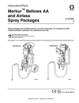
Model G30W86
shown
ti13209c
II 2 G c
Contents
Related Manuals . . . . . . . . . . . . . . . . . . . . . . . . . . . 3
Warnings . . . . . . . . . . . . . . . . . . . . . . . . . . . . . . . . . 4
Important Two-Component Material Information . 7
Isocyanate Conditions . . . . . . . . . . . . . . . . . . . . . 7
Material Self-ignition . . . . . . . . . . . . . . . . . . . . . . 7
Keep Components A and B Separate . . . . . . . . . 7
Moisture Sensitivity of Isocyanates . . . . . . . . . . . 7
Changing Materials . . . . . . . . . . . . . . . . . . . . . . . 7
Models . . . . . . . . . . . . . . . . . . . . . . . . . . . . . . . . . . . 8
Agency Approvals . . . . . . . . . . . . . . . . . . . . . . . . 9
Merkur 15:1 Packages, Ambient
(G15Wxx and G15Cxx) . . . . . . . . . . . . . . . . 9
Merkur Bellows 15:1 Packages, Ambient
(G15Bxx) . . . . . . . . . . . . . . . . . . . . . . . . . . 10
Merkur 18:1 Packages, Ambient
(G18Wxx and G18Cxx) . . . . . . . . . . . . . . . 10
Merkur 18:1 Packages, Heated
(G18Wxx) . . . . . . . . . . . . . . . . . . . . . . . . . . 10
Merkur 23:1 Packages, Ambient
(G23Wxx and G23Cxx) . . . . . . . . . . . . . . . 11
Merkur Bellows 23:1 Packages, Ambient
(G23Bxx) . . . . . . . . . . . . . . . . . . . . . . . . . . 11
Merkur 24:1 Packages, Ambient
(G24Wxx and G24Cxx) . . . . . . . . . . . . . . . 11
Merkur Bellows 24:1 Packages, Ambient
(G24Bxx) . . . . . . . . . . . . . . . . . . . . . . . . . . 12
Merkur 28:1 Packages, Ambient
(G28Wxx and G28Cxx) . . . . . . . . . . . . . . . 12
Merkur 28:1 Packages, Heated
(G28Wxx and G28Cxx) . . . . . . . . . . . . . . . 12
Merkur 30:1 Packages, Ambient
(G30Wxx and G30Cxx) . . . . . . . . . . . . . . . 13
Merkur 30:1 Packages, Heated
(G30Wxx and G30Cxx) . . . . . . . . . . . . . . . 13
Merkur Bellows 35:1 Packages, Ambient
(G35Bxx) . . . . . . . . . . . . . . . . . . . . . . . . . . 13
Installation . . . . . . . . . . . . . . . . . . . . . . . . . . . . . . . 14
General Information . . . . . . . . . . . . . . . . . . . . . 16
Prepare the Operator . . . . . . . . . . . . . . . . . . . . 16
Prepare the Site . . . . . . . . . . . . . . . . . . . . . . . . 16
Mount the Pump . . . . . . . . . . . . . . . . . . . . . . . . 16
Ventilate the Spray Booth . . . . . . . . . . . . . . . . . 17
Components . . . . . . . . . . . . . . . . . . . . . . . . . . . 17
Grounding . . . . . . . . . . . . . . . . . . . . . . . . . . . . . 18
Setup . . . . . . . . . . . . . . . . . . . . . . . . . . . . . . . . . 19
2
Operation . . . . . . . . . . . . . . . . . . . . . . . . . . . . . . . . 21
Pressure Relief Procedure . . . . . . . . . . . . . . . . 21
Flush Before Using Equipment . . . . . . . . . . . . . 21
Trigger Lock . . . . . . . . . . . . . . . . . . . . . . . . . . . . 21
Wet Cup . . . . . . . . . . . . . . . . . . . . . . . . . . . . . . . 22
Prime the Pump . . . . . . . . . . . . . . . . . . . . . . . . . 22
Install the Spray Tip . . . . . . . . . . . . . . . . . . . . . . 23
Adjust the Atomization . . . . . . . . . . . . . . . . . . . . 23
Adjust the Spray Pattern . . . . . . . . . . . . . . . . . . 24
Shutdown . . . . . . . . . . . . . . . . . . . . . . . . . . . . . . 24
Maintenance . . . . . . . . . . . . . . . . . . . . . . . . . . . . . . 25
Preventive Maintenance Schedule . . . . . . . . . . 25
Tighten Threaded Connections . . . . . . . . . . . . . 25
Flush the Pump . . . . . . . . . . . . . . . . . . . . . . . . . 25
Wet Cup . . . . . . . . . . . . . . . . . . . . . . . . . . . . . . . 25
Troubleshooting . . . . . . . . . . . . . . . . . . . . . . . . . . . 26
DataTrak Controls and Indicators . . . . . . . . . . . . . 27
DataTrak Operation . . . . . . . . . . . . . . . . . . . . . . . . 28
Setup Mode . . . . . . . . . . . . . . . . . . . . . . . . . . . . 28
Run Mode . . . . . . . . . . . . . . . . . . . . . . . . . . . . . 28
Parts . . . . . . . . . . . . . . . . . . . . . . . . . . . . . . . . . . . . 33
Ambient Models, Cart Mount or Wall Mount . . . 33
Bellows, Cart Mount . . . . . . . . . . . . . . . . . . . . . 34
Heated Models, Cart Mount or Wall Mount . . . . 36
Heated Models (Continued) . . . . . . . . . . . . . . . . 38
Kits . . . . . . . . . . . . . . . . . . . . . . . . . . . . . . . . . . . . . 39
Wall Mount Kit 24A578 (non-Bellows) . . . . . . . . 39
Cart Mount Kit 256427 (non-Bellows) . . . . . . . . 39
Bellows Cart Mount Kit 24E879 . . . . . . . . . . . . . 40
Bellows Air Control Mounting Kit . . . . . . . . . . . . 40
Pump and Gun Control Panel Kits . . . . . . . . . . . 41
Air Controls Mounting Kit (non-Bellows) . . . . . . 42
5-Gallon Suction Hose Kits . . . . . . . . . . . . . . . . 42
55-Gallon Suction Hose Kits . . . . . . . . . . . . . . . 42
PTFE Suction Hose Kits . . . . . . . . . . . . . . . . . . 42
DataTrak . . . . . . . . . . . . . . . . . . . . . . . . . . . . . . 42
Drain Valve Kit 256425 . . . . . . . . . . . . . . . . . . . 42
Overflow Chamber Kit 24E298 . . . . . . . . . . . . . 42
Mounting Dimensions . . . . . . . . . . . . . . . . . . . . . . 43
Wall Bracket (Non-Bellows) . . . . . . . . . . . . . . . . 43
Technical Data . . . . . . . . . . . . . . . . . . . . . . . . . . . . 44
Package Weights . . . . . . . . . . . . . . . . . . . . . . . . . . 45
Ambient . . . . . . . . . . . . . . . . . . . . . . . . . . . . . . . 45
Heated . . . . . . . . . . . . . . . . . . . . . . . . . . . . . . . . 45
Graco Standard Warranty . . . . . . . . . . . . . . . . . . . 46
Graco Information . . . . . . . . . . . . . . . . . . . . . . . . . 46
312798M
Related Manuals
Related Manuals
Manual
Description
312792
Merkur Displacement Pump
312793
Merkur Bellows Displacement Pump
312794
Merkur Pump Assembly
312795
Merkur Bellows Pump Assembly
312796
NXT™ Air Motor
312797
Merkur Non-Heated Spray Packages
312799
Merkur Bellows Non-Heated
Spray Packages
313255
Merkur Heated Spray Packages
3A2495
Pro Xp AA Spray Gun
307273
Fluid Outlet Filter
309524
Viscon HP Heater
306860
Back Pressure Regulator
312798M
3
Warnings
Warnings
The following warnings are for the setup, use, grounding, maintenance, and repair of this equipment. The exclamation point symbol alerts you to a general warning and the hazard symbols refer to procedure-specific risks. When
these symbols appear in the body of this manual, refer back to these Warnings. Product-specific hazard symbols and
warnings not covered in this section may appear throughout the body of this manual where applicable.
WARNING
WARNING
FIRE AND EXPLOSION HAZARD
Flammable fumes, such as solvent and paint fumes, in work area can ignite or explode. To help prevent
fire and explosion:
• Ground equipment, personnel, object being sprayed, and conductive objects in work area. See
Grounding instructions.
•
Only use grounded Graco conductive air supply hoses.
•
Use and clean equipment only in well ventilated area.
•
Use cleaning solvents with highest possible flash point when flushing or cleaning equipment.
•
Always turn the electrostatics off when flushing, cleaning or servicing equipment.
•
If there is static sparking or you feel a shock, stop operation immediately. Do not use equipment
until you identify and correct the problem.
•
Eliminate all ignition sources; such as pilot lights, cigarettes, portable electric lamps, and plastic drop
cloths (potential static arc).
•
Do not plug or unplug power cords or turn lights on or off when flammable fumes are present.
•
Keep work area free of debris, including solvent, rags and gasoline.
•
Check gun resistance daily.
•
Keep a working fire extinguisher in the work area.
SPECIAL CONDITIONS FOR SAFE USE
Equipment must comply with the following conditions to avoid a hazardous condition which can cause fire
or explosion.
• All label and marking material must be cleaned with a damp cloth (or equivalent).
• The electronic monitoring system is required to be grounded. See Grounding instructions.
ELECTRIC SHOCK HAZARD
This equipment must be grounded. Improper grounding, setup, or usage of the system can cause electric
shock.
• Turn off air supply before servicing equipment.
4
•
All electrical wiring must be done by a qualified electrician and comply with all local codes and
regulations.
•
Do not touch gun electrode when electrostatics are on.
•
Do not expose to rain. Store indoors.
312798M
Warnings
WARNING
WARNING
SKIN INJECTION HAZARD
High-pressure fluid from gun, hose leaks, or ruptured components will pierce skin. This may look like just
a cut, but it is a serious injury that can result in amputation. Get immediate surgical treatment.
•
Do not spray without tip guard and trigger guard installed.
•
Engage trigger lock when not spraying.
•
Do not point gun at anyone or at any part of the body.
•
Do not put your hand over the spray tip.
•
Do not stop or deflect leaks with your hand, body, glove, or rag.
•
Follow the Pressure Relief Procedure when you stop spraying and before cleaning, checking, or
servicing equipment.
•
Tighten all fluid connections before operating the equipment.
•
Check hoses and couplings daily. Replace worn or damaged parts immediately.
EQUIPMENT MISUSE HAZARD
Misuse can cause death or serious injury.
•
Do not operate the unit when fatigued or under the influence of drugs or alcohol.
•
Do not exceed the maximum working pressure or temperature rating of the lowest rated system
component. See Technical Data in all equipment manuals.
•
Use fluids and solvents that are compatible with equipment wetted parts. See Technical Data in all
equipment manuals. Read fluid and solvent manufacturer’s warnings. For complete information
about your material, request MSDS from distributor or retailer.
•
Do not leave the work area while equipment is energized or under pressure. Turn off all equipment
and follow the Pressure Relief Procedure when equipment is not in use.
•
Check equipment daily. Repair or replace worn or damaged parts immediately with genuine manufacturer’s replacement parts only.
•
Do not alter or modify equipment.
•
Use equipment only for its intended purpose. Call your distributor for information.
•
Route hoses and cables away from traffic areas, sharp edges, moving parts, and hot surfaces.
•
Do not kink or over bend hoses or use hoses to pull equipment.
•
Keep children and animals away from work area.
•
Comply with all applicable safety regulations.
MOVING PARTS HAZARD
Moving parts can pinch, cut or amputate fingers and other body parts.
•
Keep clear of moving parts.
•
Do not operate equipment with protective guards or covers removed.
•
Pressurized equipment can start without warning. Before checking, moving, or servicing equipment,
follow the Pressure Relief Procedure and disconnect all power sources.
TOXIC FLUID OR FUMES HAZARD
Toxic fluids or fumes can cause serious injury or death if splashed in the eyes or on skin, inhaled, or
swallowed.
•
312798M
Read MSDSs to know the specific hazards of the fluids you are using.
•
Store hazardous fluid in approved containers, and dispose of it according to applicable guidelines.
•
Always wear chemically impermeable gloves when spraying, dispensing, or cleaning equipment.
5
Warnings
WARNING
WARNING
PERSONAL PROTECTIVE EQUIPMENT
You must wear appropriate protective equipment when operating, servicing, or when in the operating
area of the equipment to help protect you from serious injury, including eye injury, hearing loss, inhalation of toxic fumes, and burns. This equipment includes but is not limited to:
6
•
Protective eyewear, and hearing protection.
•
Respirators, protective clothing, and gloves as recommended by the fluid and solvent manufacturer.
312798M
Important Two-Component Material Information
Important Two-Component Material Information
Isocyanate Conditions
Spraying or dispensing materials containing isocyanates creates potentially harmful mists, vapors, and
atomized particulates.
Read material manufacturer’s warnings and material
MSDS to know specific hazards and precautions
related to isocyanates.
Prevent inhalation of isocyanate mists, vapors, and
atomized particulates by providing sufficient ventilation in the work area. If sufficient ventilation is not
available, a supplied-air respirator is required for
everyone in the work area.
To prevent contact with isocyanates, appropriate personal protective equipment, including chemically
impermeable gloves, boots, aprons, and goggles, is
also required for everyone in the work area.
Moisture Sensitivity of
Isocyanates
Isocyanates (ISO) are catalysts used in two component
coatings. ISO will react with moisture (such as humidity)
to form small, hard, abrasive crystals, which become
suspended in the fluid. Eventually a film will form on the
surface and the ISO will begin to gel, increasing in viscosity. If used, this partially cured ISO will reduce performance and the life of all wetted parts.
NOTE: The amount of film formation and rate of crystallization varies depending on the blend of ISO, the
humidity, and the temperature.
To prevent exposing ISO to moisture:
•
Always use a sealed container with a desiccant
dryer in the vent, or a nitrogen atmosphere. Never
store ISO in an open container.
•
Use moisture-proof hoses specifically designed for
ISO, such as those supplied with your system.
•
Never use reclaimed solvents, which may contain
moisture. Always keep solvent containers closed
when not in use.
•
Never use solvent on one side if it has been contaminated from the other side.
•
Always lubricate threaded parts with ISO pump oil
or grease when reassembling.
Material Self-ignition
Some materials may become self-igniting if applied
too thickly. Read material manufacturer’s warnings
and material MSDS.
Keep Components A and B
Separate
Cross-contamination can result in cured material in
fluid lines which could cause serious injury or damage equipment. To prevent cross-contamination of
the equipment’s wetted parts, never interchange
component A (isocyanate) and component B (resin)
parts.
312798M
Changing Materials
•
When changing materials, flush the equipment multiple times to ensure it is thoroughly clean.
•
Always clean the fluid inlet strainers after flushing.
•
Check with your material manufacturer for chemical
compatibility.
•
Most materials use ISO on the A side, but some use
ISO on the B side.
7
Models
Models
Check the identification plate (ID) for the 6-digit part number of your package. Use the following matrix and tables to
define the components of your package. For example, package number G30C76 represents a Merkur package (G),
with a 30:1 ratio pump (30), cart mounting (C), and the components shown for (76) in the table on page 13.
Cart mount
ID
Wall mount
ID
ti12327a
ti12326a
G
30
C
76
First Digit
Second and Third Digits
(Ratio)
Fourth Digit
(Package Type)
Fifth and Sixth Digit
(Components Included)
G
(Merkur
Package)
8
15
18
23
24
28
30
35
15:1
18:1
23:1
C
W
B
Cart Mount
See Tables, pages 9 - 13
Wall Mount
Bellows Pump - Cart or Wall Mount
24:1
28:1
30:1
35:1
312798M
Models
Agency Approvals
Merkur Non-Heated Electrostatic Packages
G15W57, G15W58, G15C85, G15C86, G18W11, G18W12, G18C09,
G18C10, G23W13, G23W14, G23C15, G23C16, G24W11, G24W12,
G24C13, G24C14, G28W15, G28W16, G28C13, G28C14, G30W77,
G30W78, G30C75, G30C76,
II 2 G c IIA T3
Merkur Heated Electrostatic Packages
G18W13, G18W14, G28W21–G28W24, G28C19–G28C22,
G30W83–G30W86, G30C81–G30C84M
II 2 G c IIA T2
Merkur Bellows Electrostatic Packages
G15B83, G15B84, G23B33, G23B34, G24B33, G24B34, G35B33,
G35B34
Pro™ Xp 85 Manual Electrostatic Air-Assisted Spray Gun
II 2 G c IIA T3
For use in Class I Div. I hazardous locations using
Group D spray materials.
#
53
For use in Group II, Zone 1 areas using Group IIA spray
materials.
II 2 G EEx 0.24mJ
DataTrak™ Module
II 1 G
0359
Ex ia IIA T3 Ga
ITS13ATEX27862X
9902471
Class I, Div. 1,
Group D T3A
Merkur 15:1 Packages, Ambient
(G15Wxx and G15Cxx)
Maximum Inlet Air Pressure 100 psi (0.7 MPa, 7 bar)
Maximum Fluid Working Pressure: 1500 psi (10.3 MPa, 103 bar)
Model
Wall
Mount
Cart
Pump
Mount Assembly
Maximum
fluid flow
rate
gpm (lpm)
Hoses
Options
Pump
and Gun Gun
Air
Fluid Gun Fluid Gun Air
Gun Air Siphon Fluid
Controls Hose Whip Hose
Hose
Whip Hose
Kit
Filter DataTrak
G15W57 G15C85 W15FAS
2.4 (9.0)
✔
✔
✔
✔
✔
✔
✔
G15W58 G15C86 W15FBS
2.4 (9.0)
✔
✔
✔
✔
✔
✔
✔
312798M
✔
9
Models
Merkur Bellows 15:1 Packages, Ambient
(G15Bxx)
Maximum Inlet Air Pressure 100 psi (0.7 MPa, 7 bar)
Maximum Fluid Working Pressure: 1500 psi (10.3 MPa, 103 bar)
Model
Hoses
Maximum Pump
fluid flow and Gun Gun
Pump
rate
Air
Fluid Gun Fluid Gun Air
Assembly gpm (lpm) Controls Hose Whip Hose
Hose
Options
Gun Air Siphon Fluid
Whip Hose
Kit
Filter DataTrak
G15B83
B15FA0
2.4 (9.0)
✔
✔
✔
✔
✔
✔
✔*
G15B84
B15FB0
2.4 (9.0)
✔
✔
✔
✔
✔
✔
✔*
✔
* Fluid filter includes fluid drain valve.
Merkur 18:1 Packages, Ambient
(G18Wxx and G18Cxx)
Maximum Inlet Air Pressure: 100 psi (0.7 MPa, 7 bar)
Maximum Fluid Working Pressure: 1800 psi (12.4 MPa, 124 bar)
Model
Wall
Mount
Hoses
Options
Maximum Pump
fluid flow and Gun Gun
Gun
Cart
Pump
rate
Air
Fluid Gun Fluid
Air
Gun Air Siphon Fluid
Mount Assembly gpm (lpm) Controls Hose Whip Hose Hose Whip Hose
Kit
Filter DataTrak
G18W11 G18C09 W18EAS
2.0 (7.5)
✔
✔
✔
✔
✔
✔
✔
G18W12 G18C10 W18EBS
2.0 (7.5)
✔
✔
✔
✔
✔
✔
✔
✔
Merkur 18:1 Packages, Heated
(G18Wxx)
Maximum Inlet Air Pressure: 100 psi (0.7 MPa, 7 bar)
Maximum Fluid Working Pressure: 1800 psi (12.4 MPa, 124 bar)
Model
Wall
Mount
Hoses
Options
Maximum Pump
fluid flow and Gun Gun
Gun
Pump
rate
Air
Fluid Gun Fluid
Air
Gun Air Siphon Fluid
Assembly gpm (lpm) Controls Hose Whip Hose Hose Whip Hose
Kit
Filter DataTrak
G18W13 W18EAS
2.0 (7.5)
✔
✔
✔
✔
✔
✔
✔
G18W14 W18EBS
2.0 (7.5)
✔
✔
✔
✔
✔
✔
✔
10
✔
312798M
Models
Merkur 23:1 Packages, Ambient
(G23Wxx and G23Cxx)
Maximum Inlet Air Pressure: 100 psi (0.7 MPa, 7 bar)
Maximum Fluid Working Pressure: 2300 psi (15.9 MPa, 159 bar)
Model
Wall
Mount
Hoses
Options
Maximum Pump
fluid flow and Gun Gun
Gun
Cart
Pump
rate
Air
Fluid Gun Fluid
Air
Gun Air Siphon Fluid
Mount Assembly gpm (lpm) Controls Hose Whip Hose Hose Whip Hose
Kit
Filter DataTrak
G23W13 G23C15 W23DAS
1.6 (6.0)
✔
✔
✔
✔
✔
✔
✔
G23W14 G23C16 W23DBS
1.6 (6.0)
✔
✔
✔
✔
✔
✔
✔
✔
Merkur Bellows 23:1 Packages, Ambient
(G23Bxx)
Maximum Inlet Air Pressure 100 psi (0.7 MPa, 7 bar)
Maximum Fluid Working Pressure: 2300 psi (15.9 MPa, 159 bar)
Model
Hoses
Options
Maximum Pump
fluid flow and Gun Gun
Gun
Pump
rate
Air
Fluid Gun Fluid
Air
Gun Air Siphon Fluid
Assembly gpm (lpm) Controls Hose Whip Hose Hose Whip Hose
Kit
Filter DataTrak
G23B33
B23DA0
1.6 (6.0)
✔
✔
✔
✔
✔
✔
✔*
G23B34
B23DB0
1.6 (6.0)
✔
✔
✔
✔
✔
✔
✔*
✔
* Fluid filter includes fluid drain valve.
Merkur 24:1 Packages, Ambient
(G24Wxx and G24Cxx)
Maximum Inlet Air Pressure: 100 psi (0.7 MPa, 7 bar)
Maximum Fluid Working Pressure: 2400 psi (16.5 MPa, 165 bar)
Model
Wall
Mount
Hoses
Options
Maximum Pump
fluid flow and Gun Gun
Gun
Cart
Pump
rate
Air
Fluid Gun Fluid
Air
Gun Air Siphon Fluid
Mount Assembly gpm (lpm) Controls Hose Whip Hose Hose Whip Hose
Kit
Filter DataTrak
W24FAS
2.4 (9.0)
✔
✔
✔
✔
✔
✔
✔
G24W12 G24C14 W24FBS
2.4 (9.0)
✔
✔
✔
✔
✔
✔
✔
G24W11 G24C13
312798M
✔
11
Models
Merkur Bellows 24:1 Packages, Ambient
(G24Bxx)
Maximum Inlet Air Pressure 100 psi (0.7 MPa, 7 bar)
Maximum Fluid Working Pressure: 2400 psi (16.5 MPa, 165 bar)
Model
Hoses
Options
Maximum Pump
fluid flow and Gun Gun
Gun
Pump
rate
Air
Fluid Gun Fluid
Air
Gun Air Siphon Fluid
Assembly gpm (lpm) Controls Hose Whip Hose Hose Whip Hose
Kit
Filter DataTrak
G24B33
B24FA0
2.4 (9.0)
✔
✔
✔
✔
✔
✔
✔*
G24B34
B24FB0
2.4 (9.0)
✔
✔
✔
✔
✔
✔
✔*
✔
* Fluid filter includes fluid drain valve.
Merkur 28:1 Packages, Ambient
(G28Wxx and G28Cxx)
Maximum Inlet Air Pressure: 100 psi (0.7 MPa, 7 bar)
Maximum Fluid Working Pressure: 2800 psi (19.3 MPa, 193 bar)
Model
Wall
Mount
Hoses
Options
Maximum Pump
fluid flow and Gun Gun
Gun
Cart
Pump
rate
Air
Fluid Gun Fluid
Air
Gun Air Siphon Fluid
Mount Assembly gpm (lpm) Controls Hose Whip Hose Hose Whip Hose
Kit
Filter DataTrak
G28W15 G28C13 W28EAS
2.0 (7.5)
✔
✔
✔
✔
✔
✔
✔
G28W16 G28C14 W28EBS
2.0 (7.5)
✔
✔
✔
✔
✔
✔
✔
✔
Merkur 28:1 Packages, Heated
(G28Wxx and G28Cxx)
Maximum Inlet Air Pressure: 100 psi (0.7 MPa, 7 bar)
Maximum Fluid Working Pressure: 2800 psi (19.3 MPa, 193 bar)
Model
Wall
Mount
Maximum
fluid flow
Cart
Pump
rate
Mount Assembly gpm (lpm)
G28W21 G28C19 W28EAS
G28W22 G28C20 W28EBS
G28W23 G28C21 W28EAS
G28W24 G28C22 W28EBS
12
Heater
Volt
Amp
120V
19.2 Amp
120V
2.0 (7.5)
19.2 Amp
240V
2.0 (7.5)
16.7 Amp
240V
2.0 (7.5)
16.7 Amp
2.0 (7.5)
Hoses
Options
Pump
and Gun Gun
Gun
Air
Fluid Gun Fluid Air
Gun Air Siphon Fluid
Controls Hose Whip Hose Hose Whip Hose
Kit
Filter DataTrak
✔
✔
✔
✔
✔
✔
✔
✔
✔
✔
✔
✔
✔
✔
✔
✔
✔
✔
✔
✔
✔
✔
✔
✔
✔
✔
✔
✔
✔
✔
312798M
Models
Merkur 30:1 Packages, Ambient
(G30Wxx and G30Cxx)
Maximum Inlet Air Pressure: 100 psi (0.7 MPa, 7 bar)
Maximum Fluid Working Pressure: 3000 psi (20.7 MPa, 207 bar)
Model
Wall
Mount
Hoses
Options
Maximum Pump
fluid flow and Gun Gun
Gun
Pump
rate
Air
Cart
Fluid Gun Fluid
Air
Gun Air Siphon Fluid
Mount Assembly gpm (lpm) Controls Hose Whip Hose Hose Whip Hose
Kit
Filter DataTrak
G30W77 G30C75 W30CAS
1.2 (4.5)
✔
✔
✔
✔
✔
✔
✔
G30W78 G30C76 W30CBS
1.2 (4.5)
✔
✔
✔
✔
✔
✔
✔
✔
Merkur 30:1 Packages, Heated
(G30Wxx and G30Cxx)
Maximum Inlet Air Pressure: 100 psi (0.7 MPa, 7 bar)
Maximum Fluid Working Pressure: 3000 psi (20.7 MPa, 207 bar)
Model
Wall
Mount
Maximum
fluid flow
Pump
rate
Cart
Mount Assembly gpm (lpm)
G30W83 G30C81 W30CAS
1.2 (4.5)
G30W84 G30C82 W30CBS
1.2 (4.5)
G30W85 G30C83 W30CAS
1.2 (4.5)
G30W86 G30C84 W30CBS
1.2 (4.5)
Heater
Volt
Amp
Hoses
Options
Pump
and Gun Gun
Gun
Air
Fluid Gun Fluid Air
Gun Air Siphon Fluid
Controls Hose Whip Hose Hose Whip Hose
Kit
Filter DataTrak
120V
19.2 Amp
120V
19.2 Amp
240V
16.7 Amp
240V
16.7 Amp
✔
✔
✔
✔
✔
✔
✔
✔
✔
✔
✔
✔
✔
✔
✔
✔
✔
✔
✔
✔
✔
✔
✔
✔
✔
✔
✔
✔
✔
✔
Merkur Bellows 35:1 Packages, Ambient
(G35Bxx)
Maximum Inlet Air Pressure 100 psi (0.7 MPa, 7 bar)
Maximum Fluid Working Pressure: 3000 psi (20.7 MPa, 207 bar)
Model
Hoses
Options
Maximum Pump
fluid flow and Gun Gun
Gun
Pump
rate
Air
Fluid Gun Fluid
Air
Gun Air Siphon Fluid
Assembly gpm (lpm) Controls Hose Whip Hose Hose Whip Hose
Kit
Filter DataTrak
G35B33
B35DA0
1.6 (6.0)
✔
✔
✔
✔
✔
✔
✔*
G35B34
B35DB0
1.6 (6.0)
✔
✔
✔
✔
✔
✔
✔*
✔
* Fluid filter includes fluid drain valve.
312798M
13
Installation
Installation
Package components vary. See page 9 to 13 to determine the components included in your model. Items designated
as accessories are not included in the packages.
A
B
C
S
V
W
T
X
U
AB
R
H
F
J
L
K
AA
Z
N
P
ti12704b
FIG. 1. Typical Installation, Ambient, Model G30C76 Shown.
Key:
A
B
C
F
H
J
K
L
N
P
R
14
Air Shutoff Valve (accessory)
Air Filter (accessory)
Air Line Moisture Trap and Drain Valve (accessory)
Fluid Filter
Electrostatic Air-Assisted Spray Gun
Gun Swivel
Fluid Whip Hose
Air Whip Hose
Suction Hose and Tube
Strainer
Pump Grounding Wire
S
T
U
V
W
X
Y
Z
AA
AB
Gun Air Pressure Gauge
Gun Air Pressure Regulator
Bleed-type Master Air Valve (required)
DataTrak
Pump Air Pressure Gauge
Pump Air Pressure Regulator
Insert (for models without DataTrak), see FIG. 2
Electrically Conductive Gun Fluid Hose
Electrically Conductive Gun Air Hose
Electrostatic Spray Gun Grounding Wire
312798M
Installation
A
V
Y
S
B
W
C
AB
T
ti13112a
X
U
D
E
R
F
G
H
P
L
J
N
M
K
AA
Z
ti13167c
FIG. 2. Typical Installation, Heated, Model G30W86 Shown
Key:
A
B
C
D
E
F
G
H
J
K
L
M
Air Shutoff Valve (accessory)
Air Filter (accessory)
Air Line Moisture Trap and Drain Valve (accessory)
Fluid Heater
Back Pressure Regulator
Fluid Filter
Fluid Drain Valve
Electrostatic Air-Assisted Spray Gun
Gun Swivel
Fluid Whip Hose
Air Whip Hose
3 Way Valve
312798M
N
P
R
S
T
U
V
W
X
Y
Z
AA
AB
Suction Hose and Tube
Strainer
Pump Grounding Wire
Gun Air Pressure Gauge
Gun Air Pressure Regulator
Bleed Type Master Air Valve (required)
DataTrak
Pump Air Pressure Gauge
Pump Air Pressure Regulator
Insert (for models without DataTrak)
Electrically Conductive Heated Fluid Supply/Return Hose
Electrically Conductive Gun Air Hose
Electrostatic Spray Gun Grounding Wire
15
Installation
General Information
Keep the site clear of any obstacles or debris that could
interfere with the operator's movement.
NOTE: Reference numbers and letters in parentheses in
the text refer to the callouts in the figures and the parts
drawing.
Have a grounded, metal pail available for use when
flushing the system.
NOTE: Always use Genuine Graco Parts and Accessories, available from your Graco distributor. If you supply
your own accessories, be sure they are adequately
sized and pressure-rated for your system.
FIG. 1 and FIG. 2 are only guides for selecting and
installing system components and accessories. Contact
your Graco distributor for assistance in designing a system to suit your particular needs.
Prepare the Operator
All persons who operate the equipment must be trained
in the operation of all system components as well as the
proper handling of all fluids. All operators must thoroughly read all instruction manuals, tags, and labels
before operating the equipment.
Prepare the Site
Ensure that you have an adequate compressed air
supply.
NOTICE
The compressed air supply to the gun must be
clean and dry, to prevent damage to the finish. Use
a coalescing air filter in the main air supply line.
Bring a compressed air supply line from the air compressor to the pump location. Refer to the performance
charts in your pump assembly manual to find the air
consumption of your pump. Be sure all air hoses are
properly sized and pressure-rated for your system. Use
only electrically conductive hoses. The air hose should
have a 3/8 npt(m) thread. A quick disconnect coupling is
recommended.
Mount the Pump
Mount the pump directly to the wall or to a Graco cart.
See page 39 for mounting kits.
Wall-Mounted Pumps
1. Be sure the wall can support the weight of the
pump, bracket, hoses and accessories, as well as
the stress caused during operation.
2. Position the wall bracket about 4-5 ft (1.2-1.5 m)
above the floor. For ease of operation and service,
make sure the pump air inlet, fluid inlet, and fluid
outlet ports are easily accessible.
3. Using the wall bracket as a template, drill 0.4 in. (10
mm) mounting holes in the wall. Wall mounting
dimensions are shown on page 43.
4. Attach the bracket to the wall. Use 3/8 in. (9 mm)
screws that are long enough to keep the pump from
vibrating during operation.
NOTE: Be sure the bracket is level.
Cart-Mounted Pumps
Kit 24E885 is available if you plan to bolt your cart to the
floor. It includes two spacers that keep the legs stable.
Bolts not included.
Install a bleed-type shutoff valve (A) in the air line to isolate the air line components for servicing. Install an air
line filter (B) and a moisture trap and drain valve (C) to
help remove moisture and contaminants from the compressed air supply.
16
312798M
Installation
Ventilate the Spray Booth
Provide fresh air ventilation to avoid the buildup of
flammable or toxic vapors. Do not operate the gun
unless ventilation fans are operating.
Electrically interlock the gun air supply with the ventilators to prevent gun operation without ventilating fans
operating. Check and follow all National, State, and
Local codes regarding air exhaust velocity requirements.
NOTICE
High velocity air exhaust will decrease the operating efficiency of the electrostatic system. Air
exhaust velocity of 100 ft/min (31 linear
meters/minute) should be sufficient.
•
A fluid filter (F) with a 60 mesh (250 micron) stainless steel element filters particles from fluid as it
leaves the pump.
•
DataTrak (V) provides pump diagnostics and material usage information. See page 27.
Supplied with Heated Electrostatic
Packages Only
•
The back pressure regulator (E) controls back pressure to the gun and maintains proper circulation
pressure.
•
The 3-way valve (M) allows choice to circulate fluid
back to the pump or return it to the supply container.
•
A fluid drain valve (G) relieves fluid pressure in the
hose and gun.
•
The fluid heater (D) heats the fluid as it passes
through, to maintain the correct spraying viscosity.
Components
See FIG. 1 or FIG. 2. Components vary by package
ordered. See tables on pages 9 to 13. Your package
may include:
•
•
Read and understand all instructions in the supplied
heater manual 309524 before operating the heater.
Air and Fluid Hoses
The red-handled bleed-type master air valve (U) is
required in your system to relieve air trapped
between it and the air motor and gun when the valve
is closed. Do not block access to the valve.
Ambient Models
The pump air regulator (X) controls pump speed
and outlet pressure by adjusting the air pressure to
the pump.
Heated Models
•
The air relief valve (not shown) opens automatically
to prevent overpressurization of the pump.
•
The gun air regulator (T) adjusts the air pressure to
the electrostatic air-assisted spray gun (H).
•
The electrostatic air-assisted spray gun (H) dispenses the fluid. The gun houses the spray tip (not
shown), which is available in a wide range of sizes
for different spray patterns and rates of flow. Refer to
gun manual for tip installation.
•
A gun swivel (J) allows freer gun movement.
•
The suction hose (N) with strainer (P) allows the
pump to draw fluid from a 5 gallon (19 liter) pail.
312798M
•
The red hose (AA) provides the gun air supply.
•
The blue hose (Z) provides the gun fluid supply.
•
The hose bundle (L) supplies fluid and air to the
gun, and allows recirculation of fluid when the gun is
not triggered.
17
Installation
Grounding
Object being sprayed: keep the workpiece hangers
clean and grounded at all times. Follow local code.
When operating the electrostatic gun, any
ungrounded objects in the spray area (people, containers, tools, etc.) can become electrically charged.
The equipment must be grounded to reduce the risk
of static sparking and electric shock. Electric or static
sparking can cause fumes to ignite or explode.
Improper grounding can cause electric shock.
Grounding provides an escape wire for the electric
current.
The following are minimum grounding requirements for
a basic electrostatic system. Your system may include
other equipment or objects which must be grounded.
Check your local electrical code for detailed grounding
instructions. Your system must be connected to a true
earth ground.
Pump: Verify that the ground screw (GS) is attached
and tightened securely to the air motor. Connect the
other end of the ground wire (R) to a true earth ground.
All electrically conductive objects or devices in the
spray area, including paint containers, wash cans and
tools, must be properly grounded.
All persons entering
the spray area: shoes
must have conductive
Cut off
soles, such as leather, or finger of
personal grounding
glove
straps must be worn.
Rubber or plastic soles
are not conductive. The
operator must not wear
gloves that insulate the
hand from the spray gun.
The gloves must be conductive or modified as
shown.
Cut out 3 in.
(76 mm) square
from palm of
glove.
The floor of the spray area must be electrically conductive and grounded. Do not cover the floor with cardboard or any non-conductive material that would
interrupt grounding continuity.
Flammable liquids in the spray area must be kept in
approved, grounded containers. Do not store more than
the quantity needed for one shift.
Fluid supply container: follow local code.
AC
GS
R
ti12914a
FIG. 3. Ground Screw and Wire
Electrostatic Air-Assisted Spray Gun: Use only the
Graco Electrically Conductive Air Supply Hose (supplied). Connect the Gun Grounding Wire (AC) to the
ground screw (GS) on the air motor.
All solvent pails: follow local code. Use only conductive
metal pails, placed on a grounded surface. Do not place
the pail on a non-conductive surface, such as paper or
cardboard, which interrupts grounding continuity.
To maintain grounding continuity when flushing or relieving pressure, always hold a metal part of the spray gun
firmly to the side of a grounded metal pail, then trigger
the gun.
Heater: refer to the heater manual, supplied.
Air compressor: follow manufacturer’s recommendations.
All air and fluid lines must be properly grounded. Use
only grounded hoses with a maximum of 500 feet
(150m) combined hose length to ensure grounding continuity.
All electric cables must be properly grounded.
18
312798M
Installation
Setup
Ambient Packages
.
80
1. See FIG. 1. Attach the blue fluid hose (Z) to the filter
(F) outlet.
79
2. Attach the right-hand thread end of the air hose
(AA) to the gun air regulator (T).
78
(120 V only)
3. Attach the left-hand thread end of the air hose (AA)
to the air whip hose (L).
4. Attach other end of the air whip hose (L) to the air
inlet at base of gun.
5. Attach the gun swivel (J) to the gun fluid inlet.
6. Attach other end of the blue fluid hose (Z) to the
fluid whip hose (K).
ti13261a
FIG. 4. Cart Mount Non-Hazardous Location Wiring
Electrical Housing Access.
7. Attach other end of the fluid whip hose (K) to the
gun swivel (J).
8. Apply lens cover to both regulator gauge lenses.
9. Verify that suction hose fittings are tight.
Heated Packages
Remove
outer two
heater
bracket
screws.
Loosen
inner two
heater
bracket
screws.
ti13358a
The Viscon HP Heater must be installed by a qualified electrician in compliance with all state and local
codes and regulations.
Wall Mount Electrical Connections. Follow all
directions and requirements in the Viscon HP Heater
manual 309524.
Tilt the heater away from the pump for easier access to
the screws on the cover of the electrical housing.
Electrical
housing
Cart Mount Hazardous Location Wiring. The heater is
shipped with a fitting that is suitable for wiring in
hazardous locations. Follow all directions and
requirements in the Viscon HP Heater manual 309524.
Do not use the supplied electrical cord, which is
suitable only for non-hazardous location wiring.
Cart Mount Non-Hazardous Location Wiring. See
FIG. 4. Replace installed fitting with bushing (80),
shipped loose. Attach strain relief bushing (79). Follow
all directions in the Viscon HP Heater manual 309524 to
connect the 120 V supplied electrical cord (78), or
user-supplied cord for 240V applications.
312798M
ti13359a
19
Installation
5. Attach one end of the fluid whip hose (K) to the gun
swivel and the other end to the manifold (68).
Heated Hose Connections
1. Attach the right-hand thread end of the air hose
(AA) to the gun air regulator (T).
2. Attach the left-hand thread end of the air hose to the
air whip hose (L).
3. Attach the other end of the air whip hose (L) to the
air inlet at base of the gun.
4. Attach gun swivel (J) to the gun fluid inlet.
6. Attach one blue fluid hose to the manifold (68) and
to the back pressure regulator (84).
7. Attach the other blue fluid hose to the manifold (68)
and to the filter (6) outlet.
8. Apply lens cover to both regulator gauge lenses.
9. Verify that suction hose fittings and drain hose fittings are tight.
84
T
6
Z
H
J
L
AA
K
Z
68
ti13167c
FIG. 5. Hose Setup
20
312798M
Operation
Operation
guard retaining nut or hose end coupling to relieve
pressure gradually, then loosen completely. Clear
hose or tip obstruction.
Proper electrical grounding of every part of your system is essential. Read all Warnings. Follow all
Grounding instructions. See page 18. Check the gun
resistance as explained in your separate gun manual.
Pressure Relief Procedure
Flush Before Using Equipment
The equipment was tested with lightweight oil, which is
left in the fluid passages to protect parts. To avoid contaminating your fluid with oil, flush the equipment with a
compatible solvent before using the equipment. See
Prime the Pump, page 22.
Trigger Lock
1. Engage the trigger lock.
2. Turn the gun’s ES ON/OFF lever to OFF.
Always engage the trigger lock when you stop spraying
to prevent the gun from being triggered accidentally by
hand or if dropped or bumped.
Gun Trigger
Locked
ti1356a
ti12582b
Gun Trigger
Unlocked
3. Close the bleed-type master air valve.
4. Disengage the trigger lock.
5. Hold a metal part of the gun firmly to a grounded
metal pail. Trigger the gun to relieve pressure.
ti1406a
6. Engage the trigger lock.
7. Open all fluid drain valves in the system, having a
waste container ready to catch drainage. Leave
drain valve(s) open until you are ready to spray
again.
8. If you suspect the spray tip or hose is clogged or
that pressure has not been fully relieved after following the steps above, VERY SLOWLY loosen tip
312798M
21
Operation
Wet Cup
7. Hold metal part of gun (H) firmly to side of grounded
metal pail, unlock trigger, and hold trigger open.
8. Units with runaway protection only: enable the
prime/flush function by pushing the prime/flush button on the DataTrak.
Before starting, fill wet cup 1/3 full with Graco Throat
Seal Liquid (TSL) or compatible solvent.
9. Open bleed-type air valve (U). Slowly turn clockwise
pump air regulator (X) increasing pressure until
pump starts.
10. Cycle pump slowly until all air is pushed out and
pump and hoses are fully primed.
11. Units with runaway protection only: disable the
prime/flush function by pushing the prime/flush button on the DataTrak.
Wet
Cup
12. Release and lock gun trigger. Pump should stall
against pressure.
NOTICE
ti11927a
FIG. 6. Fill Wet Cup
Prime the Pump
NOTICE
For pumps with bellows, the maximum fluid inlet pressure is 15 psi (0.1 MPa, 1.0 bar). Damage to the bellows may occur if you exceed this pressure. Do not use
another pump or checking device to supply the bellows
pump.
Never allow the pump to run dry of the fluid being
pumped. A dry pump quickly accelerates to a high
speed, possibly damaging itself. If your pump accelerates quickly, or is running too fast, stop it immediately and check the fluid supply. If the supply
container is empty and air has been pumped into
the lines, refill the container and prime the pump
and the lines with fluid, or flush and leave it filled
with a compatible solvent. Be sure to eliminate all
air from the fluid system.
1. Turn the gun’s ES ON/OFF lever to OFF.
2. See FIG. 1 or FIG. 2. Lock gun trigger. Remove tip
guard and spray tip from gun (H). Refer to gun manual.
3. Close gun air regulator (T) and pump air regulator
(X) by turning knobs counterclockwise reducing
pressure to zero. Close bleed-type air valve (U).
Also verify that all drain valves are closed.
4. Connect air line to bleed type air valve (U).
5. Check that all fittings throughout system are tightened securely.
6. Position pail close to pump. Suction hose is approximately 4 ft (1.2 m) long. Do not stretch hose tight; let
it hang to assist fluid flow into pump.
22
312798M
Operation
Install the Spray Tip
4. Hold gun perpendicular and approximately 12
inches (304 mm) from surface.
5. Move gun first, then pull gun trigger to spray onto
test paper.
Follow Pressure Relief Procedure, page 21. Install the
spray tip and tip guard as explained in your separate
gun manual, supplied. Be careful not to bend the electrode wire.
The fluid output and pattern width depend on the size of
the spray tip, the fluid viscosity, and the fluid pressure.
Use the Spray Tip Selection Chart in your gun instruction manual as a guide for selecting an appropriate
spray tip for your application.
6. Increase fluid pressure in 100 psi (0.7 MPa, 7 bar)
increments, just to the point where a further
increase in fluid pressure does not significantly
improve fluid atomization. Refer to the following
example.
Example:
15:1
30:1
Adjust the Atomization
Pump Air Regulator
Increment
psi (MPa, bar)
Pump
Ratio
x
x
7 (.05, 0.5)
3.3 (0.02, 0.2)
Incremental
Fluid Pressure
psi (MPa, bar)
=
=
100 (0.7, 7.0)
100 (0.7, 7.0)
1. Do not turn on atomizing air supply.
2. Turn the gun’s ES ON/OFF lever to OFF.
3. Fluid pressure is controlled by the air pressure supplied to the pump (pump air regulator). Set fluid
pressure at low starting pressure. For low viscosity
fluids (less than 25 sec, #2 Zahn cup) with lower
percent solids (typically less than 40%), start at 300
psi (2.1 MPa, 21 bar) at pump outlet. For fluids with
higher viscosity or higher solids content, start at 600
psi (4.2 MPa, 42 bar). Refer to the following example.
Example:
Pump Air
Regulator Setting
psi (MPa, bar)
Pump
Ratio
15:1
30:1
312798M
x
x
20 (0.14, 1.4)
20 (0.14, 1.4)
Approximate
Fluid Pressure
psig (MPa, bar)
=
=
300 (2.1, 21)
600 (4.2, 42)
23
Operation
Adjust the Spray Pattern
1. See FIG. 7. Close off pattern adjustment air by turning knob clockwise (in) all the way. This sets gun for
its widest pattern.
OUT (narrower
pattern)
3. For narrower pattern, turn pattern adjustment valve
knob counterclockwise (out). If pattern is still not
narrow enough, increase air pressure to gun slightly
or use different size tip.
NOTE: Follow directions in your gun operation manual
(supplied) to test the electrostatics and to check coverage and wrap on a test piece. See Troubleshooting in
your gun operation manual if there is a problem.
IN (wider
pattern)
Shutdown
ti1345b
ti1409b
Follow Pressure Relief Procedure, page 21.
FIG. 7. Pattern Air Knob
2. See FIG. 8. Set atomizing air pressure at about 5 psi
(0.35 bar, 35 kPa) when triggered. Check spray pattern, then slowly increase air pressure until tails are
completely atomized and pulled into spray pattern.
Do not exceed 100 psi (0.7 MPa, 7 bar) air pressure
to gun.
too little
correct
air
amount of air
FIG. 8. Spray Pattern Problems
Always flush the pump before the fluid dries on the displacement rod. See Flush the Pump on page 25.
no air
24
TI0792A
312798M
Maintenance
Maintenance
Preventive Maintenance
Schedule
The operating conditions of your particular system
determine how often maintenance is required. Establish
a preventive maintenance schedule by recording when
and what kind of maintenance is needed, and then
determine a regular schedule for checking your system.
Replace lens covers on regulator gauge lenses when
dirt makes gauges difficult to read.
3. Remove the tip guard and spray tip from gun. Refer
to separate gun manual.
4. Place siphon tube in grounded metal pail containing
cleaning fluid.
5. Set pump to lowest possible fluid pressure, and start
pump.
6. Hold a metal part of the gun firmly to a grounded
metal pail.
Tighten Threaded Connections
7. Units with runaway protection only: enable the
prime/flush function by pushing the prime/flush button on the DataTrak.
Before each use, check all hoses for wear or damage.
Replace as necessary. Check that all threaded connections are tight and leak-free.
8. Trigger gun. Flush system until clear solvent flows
from gun.
Flush the Pump
9. Units with runaway protection only: disable the
prime/flush function by pushing the prime/flush button on the DataTrak.
10. Follow Pressure Relief Procedure, page 21.
Read all Warnings. Follow all Grounding instructions. See page 18.
Flush the pump:
11. Clean the tip guard, spray tip, and fluid filter element
separately, then reinstall them.
12. Clean the inside and outside of the suction tube.
•
Before first use
Wet Cup
•
When changing colors or fluids
Fill the wet cup one-half full with Graco Throat Seal Liquid (TSL). Maintain level daily.
•
Before repairing equipment
•
Before fluid dries or settles out in a dormant pump
(check the pot life of catalyzed fluids)
•
At the end of the day
•
Before storing the pump.
Flush at the lowest pressure possible. Flush with a fluid
that is compatible with the fluid you are pumping and
with the wetted parts in your system. Check with your
fluid manufacturer or supplier for recommended flushing
fluids and flushing frequency.
1. Follow Pressure Relief Procedure, page 21.
2. Be sure the ES ON/OFF lever is turned to OFF.
312798M
25
Troubleshooting
Troubleshooting
Relieve the pressure before checking or servicing
the equipment.
•
Check all possible problems and causes before
disassembling the pump.
•
For all problems related to the electrostatics, see
Troubleshooting in your gun manual.
F
Problem
Pump fails to operate.
Cause
Solution
Restricted line or inadequate air sup- Clear line or increase air supply. Check that
ply; closed or clogged valves.
the valves are open.
Obstructed fluid hose or gun; fluid
hose ID is too small.
Open, clear*; use hose with larger ID.
Fluid dried on the displacement rod.
Clean; always stop the pump at the bottom
of its stroke; keep the wet-cup 1/3 filled with
Graco throat seal liquid (TSL).
Dirty, worn, or damaged air motor
parts.
Clean or repair air motor. See manual
312796.
DataTrak models only: Air valve can- Enable runaway protection (See DataTrak
not cycle because solenoid pin is
Operation, Setup Mode, page 28). Bleed
extended
air from motor. Press
on the DataTrak
display to retract solenoid pin.
Pump operates, but output is
low on both strokes.
Restricted line or inadequate air sup- Clear line or increase air supply. Check that
ply; closed or clogged valves.
the valves are open.
Obstructed fluid hose or gun; fluid
hose ID is too small.
Open, clear*; use hose with larger ID.
Worn packings in displacement
pump.
Replace packings. See manual 312792.
Pump operates, but output is
low on downstroke.
Held open or worn ball check valves
or piston packings.
Clear valve; replace packings. See manual
312794.
Erratic or accelerated pump
speed.
Exhausted fluid supply.
Refill and prime.
Held open or worn ball check valves
or packings.
Clear valve, replace packings; see manual
312794.
Fluid being pumped is visible
in the TSL reservoir.
Worn throat packings.
Replace throat packings. See manual
312794.
Fluid is visible in the overflow
chamber.
Damaged bellows.
Replace. See manual 312793.
* To determine if the fluid hose or gun is obstructed, relieve the pressure. Disconnect the fluid hose and place a container at the pump fluid outlet to catch any fluid. Turn on the air just enough to start the pump. It the pump starts when
the air is turned on, the obstruction is in the hose or gun.
26
312798M
DataTrak Controls and Indicators
DataTrak Controls and Indicators
Key for FIG. 9
AA Runaway Limit, in cycles per minute (user settable;
00=OFF)
AB Lower Displacement (user settable)
AC Flow Rate Units (user settable to
RK Reset Key (Resets faults. Press and hold for 3 seconds to
clear the batch totalizer.) Push to toggle between flow rate
and cycle rate. With runaway protection enabled, push to
extend and retract the solenoid pin.
CF Cycle/Flow Rate
BT Batch Totalizer
GT Grand Totalizer
RT Runaway Toggle (enable/disable)
UT E1 Toggle
DT E2 Toggle
ST E5 Toggle
/min, gpm [US], gpm
[Imperial], oz/min [US], oz/min [Imperial], l/min, or cc/min)
AD LED (fault indicator when lit)
AE Display
PF Prime/Flush Key (Enables Prime/Flush mode. While in
Prime/Flush mode, runaway protection is disabled and the
batch totalizer [BT] will not count.) LED will flash while in
Prime/Flush mode.
GT
Run Mode
AE, see details at right
PF
RK
ti8622b
CF
AD
BT
RT
TI11883a
Setup Mode
UT
AC
DT
AB
PF
RK
ti8623b
AA
ST
FIG. 9. DataTrak Controls and Indicators
312798M
27
DataTrak Operation
DataTrak Operation
NOTE: The display (AE) will turn off after 1 minute to
save battery life. Press any key to wake up the display.
2. Runaway Screens 1 and 2: To reset the runaway
solenoid, close the master air valve (U). Wait for air
to completely bleed off the air motor.
NOTICE
To prevent damage to the softkey buttons, do not press
the buttons with sharp objects such as pens, plastic
cards, or fingernails.
Setup Mode
1. See FIG. 9. Press and hold
Setup menu appears.
for 5 seconds until
3. Runaway Screens 3 and 4: After the air is bled off,
push the solenoid release button down to reset the
air valve. The button will pop back up when the air
valve is repressurized.
2. To enter settings for runaway (if equipped), lower
size, and flow rate units, and to enable runaway, E1,
E2, and E5 error options, press
to change the
value, then
to save the value and move the cursor to the next data field. See page 30 for a description of E1, E2, and E5 error codes.
NOTE: Graco recommends setting runaway (if
equipped) to 60
. All DataTrak modules are
shipped with runaway protection not enabled.
Solenoid release
button
NOTE: When runaway, E1, E2, and E5 error options are
enabled, a ✓ will appear on the setup screen. See FIG.
9.
3. Move the cursor to the E5 error enable option field,
then press
ti11902a
FIG. 10. Reset the Air Valve
once more to exit Setup mode.
Run Mode
4. Runaway Screens 5 and 6: Press
to clear the
diagnostic code and reset the runaway solenoid.
Runaway
NOTE: DataTrak is available with and without runaway
protection. Packages with M02xxx air motors ship without a runaway solenoid. All other packages are
equipped with a runaway solenoid.
1. See FIG. 9. If pump runaway occurs, the runaway
solenoid will actuate, stopping the pump. The LED
(AD) will flash and the display (AE) will indicate a
runaway condition (see Table 1). The display will
cycle through six instruction screens.
28
5. Open master air valve (U) to restart pump.
NOTE: To disable runaway monitoring, go to setup
mode and set runaway value to 0 (zero) or toggle (RT)
off
(see FIG. 9).
312798M
DataTrak Operation
Prime/Flush
Diagnostics
1. See FIG. 9. To enter Prime/Flush mode, press any
key to wake up the display, then press
. The
Prime/Flush symbol will appear in the display and
DataTrak can diagnose several problems with the pump.
When the monitor detects a problem, the LED (AD, FIG.
9) will flash and a diagnostic code will appear on the display. See Table 1.
the LED will flash
To acknowledge the diagnosis and return to the normal
.
operating screen, press
once to wake up the display,
and once more to clear the diagnostic code screen.
2. While in Prime/Flush mode, runaway protection is
disabled and the batch totalizer (BT) will not count.
The grand totalizer (GT) continues to count.
3. To exit Prime/Flush mode, press any key to wake up
the display, then press
. The Prime/Flush symbol will disappear from the display and the LED will
stop flashing.
Counter/Totalizer
See FIG. 9. The last digit of the batch totalizer (BT) represents tenths of gallons or liters. To reset the totalizer,
press any key to wake up the display, then press and
hold
•
•
•
for 3 seconds.
If AC is set to gallons or ounces, BT and GT display gallons.
If AC is set to liters or cc, BT and GT display
liters.
If AC is set to cycles, BT and GT display cycles.
Press
to toggle between flow rate units and cycles.
A letter under the BT display indicates that both BT and
GT are displaying gallons (g) or liters (l). No letter
means both BT and GT are displaying cycles.
Display
See FIG. 9. The display (AE) will turn off after 1 minute
of inactivity in Run mode or 3 minutes in Setup mode.
Press any key to wake up the display.
NOTE: DataTrak will continue to count cycles when display is off.
NOTE: The display (AE) may turn off if a high-level static
discharge is applied to the DataTrak. Press any key to
wake up the display.
312798M
29
DataTrak Operation
Table 1: Diagnostic Codes
Symbol
30
Code
Code Name
Diagnosis
Cause
Runaway
(DataTrak only)
Pump running faster than set
runaway limit.
E-1
Diving Up
Leak during upstroke.
Worn piston valve or packings.
E-2
Diving Down
Leak during downstroke.
Worn intake valve.
E-3
Low Battery
Battery voltage too low to stop
runaway.
Low battery. Replace battery;
see page 31.
• Increased air pressure.
• Increased fluid output.
• Exhausted fluid supply.
E-4
Service
Problem with stopping runaway. • Damaged solenoid.
Component 1
• Damaged valve carriage.
(units with
• Runaway (RT, FIG. 9) protection may be enabled with
runaway
pump that is not equipped with
protection only)
a runaway solenoid valve.
Enter setup screen and disable runaway protection.
E-4
Disconnected
Solenoid is disconnected.
• Solenoid unplugged.
Solenoid
• Damaged solenoid wires.
(units with
Solenoid is not engaging piston • Bracket and solenoid not tight
runaway
cup
against air valve housing.
protection only)
E-5
Service
Component 2
Problem with sensing valve
movement.
E-6
Blown Fuse
Fuse is blown. Replace fuse;
see page 31.
•
•
•
•
Sensors unplugged.
Sensors mounted incorrectly.
Damaged sensors.
Damaged valve carriage.
• Faulty solenoid or solenoid
wiring.
• Extreme temperatures (above
140°F [60°C]).
• Runaway (RT, FIG. 9) protection may be enabled with
pump that is not equipped with
a runaway solenoid valve.
Enter setup screen and disable runaway protection.
312798M
DataTrak Operation
Replace DataTrak Battery or Fuse
4. Remove two screws on back of module to access
battery.
To reduce the risk of fire and explosion, the battery
and fuse must be replaced in a non-hazardous location.
Use only an approved replacement battery, shown in
TABLE 2, and an approved fuse, shown in TABLE 3.
Use of an unapproved battery or fuse will void
Graco’s warranty and Intertek and Ex approvals.
Replace Battery
5. Disconnect the used battery and replace with an
approved battery. See Table 2.
Table 2. Approved Batteries
Energizer alkaline # 522
Varta alkaline # 4922
Ultralife lithium # U9V
Duracell alkaline # MN1604
1. Unscrew cable from the back of the reed switch
assembly. See FIG. 11.
2. Remove the cable from the two cable clips.
ti11992a
FIG. 11. Disconnect DataTrak
3. Remove DataTrak module from bracket. See FIG.
12. Take module and attached cable to a non-hazardous location.
ti11884a
FIG. 12. Remove DataTrak
312798M
31
DataTrak Operation
Replace Fuse
Table 3. Approved Fuses
DataTrak Part
Number
1. Remove the screw, metal strap, and plastic holder.
2. Pull the fuse away from the board.
289822
3. Replace with an approved fuse from Table 3.
All other part
numbers
Series*
Fuse
Required
A or B
C and later
A
B and later
24C580
24V216
24C580
24V216
* FIG. 13 shows where to find the Series letter.
Solenoid Cable
Connection
Fuse
Sensor Cable
Connection
Series Letter
(last digit of code)
Battery
ti11994b
FIG. 13. DataTrak Battery and Fuse Location
32
312798M
Parts
Parts
Ambient Models, Cart Mount or Wall Mount
9b
10
Model G30C76 shown.
9
3a
3b
8
9a
2
22
37
16
48
ti12637b
65
1
13
7
53
6
4
5
312798M
ti13169a
33
Parts
Bellows, Cart Mount
3a
3b
2
56
32
55
17
57
48
58
17
1
17
7
13
6
30
4
60
43
46
44
45
5
ti15429a
34
312798M
Parts
Parts
Ref Part
1
2
3a
3b
4
5
6
7
8
9
9a
9b
10
11
12
13
22
37
Varies
Ref Part
Description
Pump Assembly, see Model tables,
pages 9-13, and Manual 312794
or 312795 (Bellows)
PANEL, air control, see page 41
24A581
G15xxx to G30xxx models
24A584
G35xxx models, 85 psi
24A576 DATATRAK, assembly; see manual
313541
----INSERT, panel (included with Part 2)
HOSE, suction (includes Part 5)
256422
G15Cxx, G18Cxx, G24Cxx,
G28Cxx
256424
G15Bxx, G15Wxx, G18Wxx,
G24Bxx, G24Wxx, G28Wxxx
256421
G23Cxx, G30Cxx
256423
G23Bxx, G23Wxx, G30Wxx,
G35Bxx
----STRAINER (included with Part 4)
24A587 FILTER, fluid (includes Part 7)
235208 FITTING, union, 3/8-18 npsm x
3/8-18 npt (included with Part 6)
189018 SWIVEL, fluid hose
24A956 HOSE, coupled, air and fluid, 25 ft.
(includes Parts 9a and 9b)
236130 HOSE, air whip, 3 ft., 0.9 m, (included
with Part 9)
----GROUND WIRE, spray gun (included
with Part 9)
H85M10 GUN, Pro Xp 85
AEM413 TIP (not shown)
TIP OPTION (not shown)
AEMxxx
AEFxxx
ADAPTER, outlet
121237
3/8 nptm x 1/2 nptf, used on
G18xxx and G28xxx models
121238
3/8 nptm x 3/4 nptf, used on
G15xxx and G24xxx models
239069 HOSE, fluid, whip, 2 ft. (0.6 m)
166846 ADAPTER, for fluid whip hose,
1/4 npt x 1/4 npsm
312798M
Qty
1
1
1
1
1
41
Description
256425
VALVE, drain, stainless steel (includes
Parts 44 and 45); Bellows packages
only
44 ----COUPLING, hose, drain (included with
Part 41)
45 ----HOSE, drain (included with Part 41)
48 238909 WIRE, grounding assembly
85▲ 15W718 LABEL, warning, not shown
86▲ 15W719 LABEL, warning, not shown
Description
16
-----
49
24E883
1
1
1
51
-----
53
256427
1
1
54
24A578
NUT, lock, M5 x 0.08 (included with
Part 49)
AIR CONTROLS MOUNTING KIT,
wall, (includes 16 and 51)
SCREW, hex head, M8 x 16 mm
(included with Part 49)
CART MOUNTING KIT, see page 39
(GxxCxx models only)
WALL MOUNTING KIT, see page 39
(GxxWxx models only)
1
1
1
1
1
Qty
2
1
2
1
1
Bellows Mounting Parts
1
Ref
Part
1
1
1
17
30
32
55
111799
24E880
105332
-----
56
1
57
58
60
1
1
1
Non-Bellows Mounting Parts
Ref Part
1
Qty
Description
Qty.
SCREW, M8 x 16, included with Part 30
PLATE, mounting; includes hardware
LOCK NUT, 5 mm
MOUNTING WEDGE, left, air control
panel, cart mount
----MOUNTING WEDGE, right, air control
panel, cart mount
110873 SCREW, M5 x 0.8
104541 LOCK NUT, M8
24E879 CART MOUNTING KIT; see Bellows Cart
Mount Kit, page 40
8
1
2
1
1
2
4
1
▲Replacement Warning labels, signs, tags, and cards are
available at no cost.
35
Parts
Heated Models, Cart Mount or Wall Mount
Model G30W86 shown
3a
3b
2
ti13112a
66
67
67
84
63
62
64
1
48
77
60
61b
61a
6
74
73
83a
(wall
mount
models)
81
83b
(cart
mount
models)
76
75
61
82
ti13018a
5
36
4
69
70
72
71
312798M
Parts
Non-Hazardous Location Electrical
Cord Parts (Cart Mount Only)
16
49
80
79
78
(120 V
only)
51
ti15484b
ti13261a
65
16
10
53
8
9a
22
9
9b
68
ti13114a
312798M
ti13260b
37
Parts
Heated Models (Continued)
Ref Part
Description
1
Varies
2
3a
24A581
24A576
3b
4
-----
Pump Assembly, see Model tables,
pages 9-13, and Manual 312794
PANEL, air controls
DATATRAK, assembly, see manual
313541
INSERT, panel (included with Part 2)
HOSE, suction, assembly (includes Part
5)
G18xxx and G28xxx Models
G30xxx Models
STRAINER, suction (included with Part
4)
FILTER, fluid, sst, see manual 307273
SWIVEL, fluid hose
HOSE BUNDLE, air and fluid
HOSE, air whip, 3 ft. (0.9 m)
GROUND WIRE, spray gun
GUN, Pro Xp 85
GUN TIP (not shown)
TIP OPTION (not shown)
NUT, lock, M5 x 0.08 (included with Part
49)
HOSE, fluid, whip, 2 ft (0.6 m)
GROUND WIRE, pump
AIR CONTROLS MOUNTING KIT, wall
mount, (includes 16 and 51)
SCREW, hex head, M8 x 16 mm
(included with Part 49)
CART MOUNTING KIT, see page 39
(GxxCxx models only)
WALL MOUNTING KIT, see page 39
(GxxWxx models only)
BRACKET, heated, kit, includes 64, 65,
and 66)
HEATER, fluid, includes 61a and 61b
120V, see manual 309524
240V, see manual 309524
WASHER
SCREW, M8 x 1.25 in.
CAPSCREW, hex hd,
1/4-20 x 3/4 in. (19mm)
WASHER, 1/4 in.
SCREW, M8 x 25
NUT
SCREW, M8 x 1.25
INSULATOR, heat
MANIFOLD, recirculating, 1/4 npsm
5
256422
256423
-----
6
8
9
9a
9b
10
11
12
16
239300
189018
239352
236130
----H85M10
AEM413
AEMxxx
-----
22
48
49
239069
238909
24E883
51
-----
53
256427
54
24A578
60
24A590
61
245848
245863
61a ----61b ----62 100022
63
64
65
66
67
68
38
100527
------------167002
239864
Qt
y
1
1
1
1
1
Ref Part
69
70
71
72
73
74
1
75
1
1
1
1
1
1
1
1
2
76
77
78
79
80
1
1
1
81
2
1
82
83a
1
83b
1
84
1
85
86
4
4
2
Qt
y
Description
UNION, swivel
15V521
G18xxx and G28xxx Models
15V522
G30xxx Models
113834 BALL VALVE, 3 way, 1/4 npt(m), sst
239062 HOSE, drain, nylon, sst fittings,
1/4 in. (6 mm) ID; 1/4 npsm(f)
166866 ELBOW, 1/4 npt (m x f), sst
117627 FITTING, coupler
UNION, swivel
114190
G18xxx and G28xxx Models
236892
G30xxx Models
239153 HOSE, fluid, nylon, sst fittings; 1/2 in (13
mm) ID, 1/2 npt (mbe), 19.5 in. (0.5
m) long
239108 HOSE, fluid, recirculation
166846 ADAPTER, 1/4-18 npsm x 1/4-18 npt
15W730 CORD, electrical (120V cart mount
packages only)
112408 STRAIN RELIEF, 90° (120V cart mount
packages only)
BUSHING
For use with supplied cord (120V
107219
cart mount packages only),
3/4 npt(m) x 1/2 nptf
185065
Supplied with heater for conduit
applications
113934 UNION, swivel, heater inlet, 90°, sst, 1/2
npt(fbe)
502265 BUSHING, reducer, pipe
235207 UNION, swivel, sst, 3/8 npt(m) x 3/8
npsm(f), wall mount packages only
207123 UNION, swivel, 90°, cart mount packages only
238926 REGULATOR, back pressure, sst, see
manual 306860
15W718 LABEL, warning, not shown
▲
15W719 LABEL, warning, not shown
▲
1
1
1
2
1
1
1
1
3
1
1
1
1
1
1
1
1
1
1
▲Replacement Warning labels, signs, tags, and cards are
available at no cost.
2
4
4
4
4
1
312798M
Kits
Kits
Wall Mount Kit 24A578 (non-Bellows)
Ref.
101
102
101
Description
SCREW, cap, M8 x 1.25
PLATE, wall mount
Qty.
4
1
NOTE: Air Controls Mounting Kit 24E883 also is
required for wall mounting a package that has a control
panel. See page 42.
102
ti12633a
Cart Mount Kit 256427 (non-Bellows)
202
205
208
207
209
Ref.
201
202
203
204
205
206
207
208
209
Part
--------119451
119452
----15C871
115480
116630
-----
Description
CART, frame
HANDLE, cart
WHEEL, semi-pneumatic
CAP, hub
SLEEVE, cart handle
CAP, leg
KNOB, t-handle
SCREW, carriage
BRACKET, heater, cart
Qty.
1
1
2
2
2
2
2
2
1
201
203
204
206
ti12634a
312798M
39
Kits
Bellows Cart Mount Kit 24E879
15a 15b
Bellows Air Control Mounting
Kit
Kit 24E884 includes right and left mounting wedges
(55 and 56), lock nuts (32) and screws (37).
18
58 (x 4)
17 (x 4)
56
55
17 (x 4)
32
57
30
ti15483a
ti15580a
Ref
15a
15b
17
18
30
58
40
Description
Washer (not used)
Screw (not used)
Screw, M8 x 16
Spacers (not used)
Plate, mounting
Lock nut, 13 mm
Qty.
2
2
8
2
1
4
312798M
Kits
Pump and Gun Control Panel Kits
304
311 324
310
307 308
313
310
319
308
316
307
303
306
314
317
305
325
304
303
302
309
315
312
301
ti13467a
ti13565a
321
Kit 24A581 and Kit 24A584
Ref. Part
301 114362
302 15T643
303
----304
305
306
307
121212
15T536
---------
308
309
310
311
15T498
15T866
15T500
312
313
314
315
316
317
318
319
320
321
322
113498
120306
164672
15T538
114381
15T539
116514
------------105332
---------
324
325
24P814
24P813
312798M
Description
Qty.
VALVE, ball
1
SWIVEL, tee, 3/8 npt(m) x 1/2T
1
TUBE, 1/2 OD, cut to fit,
1.3 ft.
order Tubing Kit 24D496
ELBOW, swivel, 1/2T x 3/8 npt(m)
3
REGULATOR, air, pump, 3/8 npt
1
ELBOW, swivel, 5/32 T x 1/4 npt
1
TUBE, black, cut to fit,
4 in.
order Tubing Kit 24D496
SWIVEL, 90°, 5/32T x 1/8 npt(f)
2
ELBOW, swivel, 5/32T x 1/8 npt
1
GAUGE, pressure
2
VALVE, safety
1
Kit 24A581 (100 psi)
Kit 24A584 (85 psi)
ADAPTER
1
NUT, regulator
1
SCREW, cap, button head
2
REGULATOR, air, gun, 3/8 npt
1
NUT, regulator
1
PANEL
1
LABEL, panel (not shown)
1
INSERT
1
NUT, lock (not shown)
2
ELBOW, 1/2T x 1/2 npt
1
COVER, lens, 12 sticker sheet (not shown),
1
order Kit 24A540 for 5 sheets
RING, grounding
1
RING, grounding
1
41
Kits
Air Controls Mounting Kit
(non-Bellows)
PTFE Suction Hose Kits
For pumping acid materials that are compatible with
PTFE. Includes suction hose, swivel, and strainer.
Includes one mounting bracket (49), two lock nuts
(16), and two hex head screws (51).
Kit
Packages
24E883
Air Controls Mounting Kit, Wall Mount
5-Gallon Suction Hose Kits
Includes suction hose (4) and strainer (5).
Kit
Packages
Cart
256422 Ambient: G15Cxx, G18Cxx,
G24Cxx, G28Cxx
Cart
256423 Ambient: G23Wxx, G30Wxx
Both
Wall
Ambient Bellows: G23Bxx, G35Bxx Cart
Heated: G30xxx
256424 Ambient: G15Wxx, G18Wxx,
G24Wxx, G28Wxxx
Description
Wall/Cart
24B337 3/4 in. hose, PTFE lined, with swivel Cart
elbow
24B338 1 in. hose, PTFE lined, with swivel
elbow
Cart
24B424 3/4 in. hose, PTFE lined, with
straight swivel
Wall
24B425 1 in. hose, PTFE lined, with straight Wall
swivel
Wall/Cart
256421 Ambient G23Cxx, G30Cxx
Heated: G18xxx, G28xxx
Kit
Both
Wall
Ambient Bellows: G15Bxx, G24Bxx Cart
55-Gallon Suction Hose Kits
Includes suction hose, bung adapter, and strainer.
DataTrak
NOTE: See DataTrak manual, 313541, for all DataTrak
related part numbers and kit information, including the
reed switch and solenoid.
Drain Valve Kit 256425
Includes drain valve (43), coupling (44), and hose(45).
Overflow Chamber Kit 24E298
Merkur Bellows models only. See Manual 312793.
Includes overflow cup, with seals and necessary hardware.
24A954 - 3/4 in. hose
24B598 - 1 in. hose
42
312798M
Mounting Dimensions
Mounting Dimensions
Wall Bracket (Non-Bellows)
11 in.
(279 mm)
4 in.
(102 mm)
Four 0.40 in. (10 mm)
mounting holes
312798M
ti12833a
43
Technical Data
Technical Data
Merkur Electrostatic Spray Packages
U.S.
Maximum Fluid Working Pressure
Metric
See Models table on page 8.
Maximum Fluid Inlet Pressure
(Bellows)
15 psi
0.1 MPa, 1.0 bar
Maximum Pump Air Inlet Pressure
100 psi
0.7 MPa, 7.0 bar
Maximum Gun Air Inlet Pressure
100 psi
0.7 MPa, 7.0 bar
Ratio
See Models table on page 8.
Ambient Air Temperature Range
35-120°F
2-49°C
Maximum Operating Temperature
120°F
49°C
Sound Data
Wetted Parts (displacement pump)
See Technical Data in air motor manual 312796.
See manual 312792 (Merkur) or 312793 (Merkur Bellows).
Wetted Parts (spray gun)
See manual 3A2495.
Wetted Parts (fluid hoses)
nylon
Wetted Parts (suction assembly)
stainless steel, nylon
Wetted Parts (fluid filter)
See manual 307273.
Wetted Parts (drain valve)
stainless steel, nylon
44
312798M
Package Weights
Package Weights
Ambient
Ratio, Package
Heated
Weight in
lb (kg)
Cart Mount
Ratio, Package
Weight in
lb (kg)
Cart Mount
15:1, G15C85
112 (51)
28:1, G28C19
182 (83)
15:1, G15C86
113 (51)
28:1, G28C20
183 (83)
15:1, G15B83
137 (62)
28:1, G28C21
182 (83)
15:1, G15B84
138 (63)
28:1, G28C22
183 (83)
18:1, G18C09
111 (50)
30:1, G30C81
173 (79)
18:1, G18C10
112 (51)
30:1, G30C82
174 (79)
23:1, G23C15
109 (49)
30:1, G30C83
173 (79)
23:1, G23C16
110 (50)
30:1, G30C84
174 (79)
23:1, G23B33
133 (60)
Wall Mount
23:1, G23B34
134 (61)
18:1, G18W13
156 (71)
24:1, G24C13
114 (52)
18:1, G18W14
157 (71)
24:1, G24C14
115 (52)
28:1, G28W21
156 (71)
24:1, G24B33
137 (62)
28:1, G28W22
157 (71)
24:1, G24B34
138 (63)
28:1, G28W23
156 (71)
28:1, G28C13
114 (52)
28:1, G28W24
157 (71)
28:1, G28C14
115 (52)
30:1, G30W83
147 (67)
30:1, G30C75
106 (48)
30:1, G30W84
148 (67)
30:1, G30C76
107 (48)
30:1, G30W85
147 (67)
35:1, G30B33
133 (60)
30:1, G30W86
148 (67)
35:1, G30B34
134 (61)
Wall Mount
15:1, G15W57
85 (39)
15:1, G15W58
86 (39)
18:1, G18W11
85 (39)
18:1, G18W12
86 (39)
23:1, G23W13
82 (37)
23:1, G23W14
83 (38)
24:1, G24W11
88 (40)
24:1, G24W12
89 (40)
28:1, G28W15
86 (39)
28:1, G28W16
87 (40)
30:1, G30W77
79 (36)
30:1, G30W78
80 (36)
312798M
45
Graco Standard Warranty
Graco warrants all equipment referenced in this document which is manufactured by Graco and bearing its name to be free from defects in
material and workmanship on the date of sale to the original purchaser for use. With the exception of any special, extended, or limited warranty
published by Graco, Graco will, for a period of twelve months from the date of sale, repair or replace any part of the equipment determined by
Graco to be defective. This warranty applies only when the equipment is installed, operated and maintained in accordance with Graco’s written
recommendations.
This warranty does not cover, and Graco shall not be liable for general wear and tear, or any malfunction, damage or wear caused by faulty
installation, misapplication, abrasion, corrosion, inadequate or improper maintenance, negligence, accident, tampering, or substitution of
non-Graco component parts. Nor shall Graco be liable for malfunction, damage or wear caused by the incompatibility of Graco equipment with
structures, accessories, equipment or materials not supplied by Graco, or the improper design, manufacture, installation, operation or
maintenance of structures, accessories, equipment or materials not supplied by Graco.
This warranty is conditioned upon the prepaid return of the equipment claimed to be defective to an authorized Graco distributor for verification of
the claimed defect. If the claimed defect is verified, Graco will repair or replace free of charge any defective parts. The equipment will be returned
to the original purchaser transportation prepaid. If inspection of the equipment does not disclose any defect in material or workmanship, repairs will
be made at a reasonable charge, which charges may include the costs of parts, labor, and transportation.
THIS WARRANTY IS EXCLUSIVE, AND IS IN LIEU OF ANY OTHER WARRANTIES, EXPRESS OR IMPLIED, INCLUDING BUT NOT LIMITED
TO WARRANTY OF MERCHANTABILITY OR WARRANTY OF FITNESS FOR A PARTICULAR PURPOSE.
Graco’s sole obligation and buyer’s sole remedy for any breach of warranty shall be as set forth above. The buyer agrees that no other remedy
(including, but not limited to, incidental or consequential damages for lost profits, lost sales, injury to person or property, or any other incidental or
consequential loss) shall be available. Any action for breach of warranty must be brought within two (2) years of the date of sale.
GRACO MAKES NO WARRANTY, AND DISCLAIMS ALL IMPLIED WARRANTIES OF MERCHANTABILITY AND FITNESS FOR A
PARTICULAR PURPOSE, IN CONNECTION WITH ACCESSORIES, EQUIPMENT, MATERIALS OR COMPONENTS SOLD BUT NOT
MANUFACTURED BY GRACO. These items sold, but not manufactured by Graco (such as electric motors, switches, hose, etc.), are subject to
the warranty, if any, of their manufacturer. Graco will provide purchaser with reasonable assistance in making any claim for breach of these
warranties.
In no event will Graco be liable for indirect, incidental, special or consequential damages resulting from Graco supplying equipment hereunder, or
the furnishing, performance, or use of any products or other goods sold hereto, whether due to a breach of contract, breach of warranty, the
negligence of Graco, or otherwise.
FOR GRACO CANADA CUSTOMERS
The Parties acknowledge that they have required that the present document, as well as all documents, notices and legal proceedings entered into,
given or instituted pursuant hereto or relating directly or indirectly hereto, be drawn up in English. Les parties reconnaissent avoir convenu que la
rédaction du présente document sera en Anglais, ainsi que tous documents, avis et procédures judiciaires exécutés, donnés ou intentés, à la suite
de ou en rapport, directement ou indirectement, avec les procédures concernées.
Graco Information
For the latest information about Graco products, visit www.graco.com.
For patent information, see www.graco.com/patents.
TO PLACE AN ORDER, contact your Graco distributor or call to identify the nearest distributor.
Phone: 612-623-6921 or Toll Free: 1-800-328-0211 Fax: 612-378-3505
All written and visual data contained in this document reflects the latest product information available at the time of publication.
Graco reserves the right to make changes at any time without notice.
Original instructions. This manual contains English. MM 312798
Graco Headquarters: Minneapolis
International Offices: Belgium, China, Japan, Korea
GRACO INC. AND SUBSIDIARIES • P.O. BOX 1441 • MINNEAPOLIS MN 55440-1441 • USA
Copyright 2008, Graco Inc. All Graco manufacturing locations are registered to ISO 9001.
www.graco.com
Revision M - July 2014