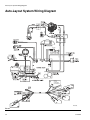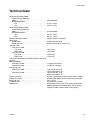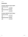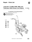
1
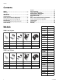
Repair - Parts List
LineLazer™ IV 3900, 5900 Auto-Layout™ System
Airless Line Stripers
312195K
EN
For application of line striping materials. For professional use only. Not for use in
explosive atmospheres.
3300 psi (22.8 MPa, 228 bar) Maximum Working Pressure
Important Safety Instructions
Read all warnings and instructions in this manual.
Save these instructions.
See page 2 for model information.
312190
309055
310643
312345
311254
312307
ti10233a
Models
Contents
Models . . . . . . . . . . . . . . . . . . . . . . . . . . . . . . . . . . . . . . . . . 2
Warnings . . . . . . . . . . . . . . . . . . . . . . . . . . . . . . . . . . . . . . . 3
Tip Selection . . . . . . . . . . . . . . . . . . . . . . . . . . . . . . . . . . . . 5
Maintenance . . . . . . . . . . . . . . . . . . . . . . . . . . . . . . . . . . . . 6
Troubleshooting . . . . . . . . . . . . . . . . . . . . . . . . . . . . . . . . . 7
Auto-Layout Can Actuator Adjustment. . . . . . . . . . . . . . 10
Bearing Housing and Connecting Rod . . . . . . . . . . . . . . 11
Drive Housing . . . . . . . . . . . . . . . . . . . . . . . . . . . . . . . . . . 12
Pinion Assembly/Clutch Armature/Clamp . . . . . . . . . . . 13
Clutch Housing . . . . . . . . . . . . . . . . . . . . . . . . . . . . . . . . . 15
Engine . . . . . . . . . . . . . . . . . . . . . . . . . . . . . . . . . . . . . . . . 16
Pressure Control. . . . . . . . . . . . . . . . . . . . . . . . . . . . . . . . 17
Trigger Sensor Adjustment . . . . . . . . . . . . . . . . . . . . . . . 19
Distance Sensor Replacement . . . . . . . . . . . . . . . . . . . . 19
Control Board Diagnostics . . . . . . . . . . . . . . . . . . . . . . . 20
Displacement Pump . . . . . . . . . . . . . . . . . . . . . . . . . . . . . 21
Parts. . . . . . . . . . . . . . . . . . . . . . . . . . . . . . . . . . . . . . . . . . 22
Parts - Drive and Pinion Housing Assemblies . . . . . . . . 23
Auto-Layout System Wiring Diagram . . . . . . . . . . . . . . . 34
Technical Data. . . . . . . . . . . . . . . . . . . . . . . . . . . . . . . . . . 35
Dimensions . . . . . . . . . . . . . . . . . . . . . . . . . . . . . . . . . . . . 36
Warranty . . . . . . . . . . . . . . . . . . . . . . . . . . . . . . . . . . . . . . 38
Models
Manual
Language
312195
English
312196
French
312197
Spanish
312198
Dutch
312199
German
312200
Italian
312201
Turkish
✔
312202
Greek
✔
312203
Croatian
✔
312204
Portuguese
✔
312205
Danish
312206
Finnish
312207
Swedish
312208
Norwegian
312209
Russian
312210
Estonian
312211
Latvian
312212
Lithuanian
312213
Polish
312214
Hungarian
312215
Czech
312216
Slovakian
312217
Slovenian
312218
Romanian
312219
Bulgarian
3900 Line Stripers
253920
✔
✔
253953
255151
✔
✔
255152
5900 Line Stripers
253921
✔
✔
253954
255153
255154
2
✔
✔
✔
✔
✔
✔
312195K
Warnings
Warnings
The following warnings are for the setup, use, grounding, maintenance, and repair of this equipment. The exclamation point symbol alerts you to a general warning and the hazard symbol refers to procedure-specific risk. Refer back
to these warnings. Additional, product-specific warnings may be found throughout the body of this manual where
applicable.
WARNING
FIRE AND EXPLOSION HAZARD
Flammable fumes, such as solvent and paint fumes, in work area can ignite or explode. To help prevent
fire and explosion:
• Use equipment only in well ventilated area.
• Do not fill fuel tank while engine is running or hot; shut off engine and let it cool. Fuel is flammable
and can ignite or explode if spilled on hot surface.
• Eliminate all ignition sources; such as pilot lights, cigarettes, portable electric lamps, and plastic drop
cloths (potential static arc).
• Keep work area free of debris, including solvent, rags and gasoline.
• Do not plug or unplug power cords, or turn power or light switches on or off when flammable fumes
are present.
• Ground all equipment in the work area. See Grounding instructions.
• Use only grounded hoses.
• Hold gun firmly to side of grounded pail when triggering into pail.
• If there is static sparking or you feel a shock, stop operation immediately. Do not use equipment
until you identify and correct the problem.
• Keep a working fire extinguisher in the work area.
CARBON MONOXIDE HAZARD
Exhaust contains poisonous carbon monoxide, which is colorless and odorless. Breathing carbon
monoxide can cause death. Do not operate in an enclosed area.
SKIN INJECTION HAZARD
High-pressure fluid from gun, hose leaks, or ruptured components will pierce skin. This may look like just
a cut, but it is a serious injury that can result in amputation. Get immediate surgical treatment.
• Do not point gun at anyone or at any part of the body.
• Do not put your hand over the spray tip.
• Do not stop or deflect leaks with your hand, body, glove, or rag.
• Do not spray without tip guard and trigger guard installed.
• Engage trigger lock when not spraying.
• Follow Pressure Relief Procedure in this manual, when you stop spraying and before cleaning,
checking, or servicing equipment.
PRESSURIZED EQUIPMENT HAZARD
Fluid from the gun/dispense valve, leaks, or ruptured components can splash in the eyes or on skin and
cause serious injury.
• Follow Pressure Relief Procedure in this manual, when you stop spraying and before cleaning,
checking, or servicing equipment.
• Tighten all fluid connections before operating the equipment.
• Check hoses, tubes, and couplings daily. Replace worn or damaged parts immediately.
PRESSURIZED ALUMINUM PARTS HAZARD
Do not use 1,1,1-trichloroethane, methylene chloride, other halogenated hydrocarbon solvents or fluids
containing such solvents in pressurized aluminum equipment. Such use can cause serious chemical
reaction and equipment rupture, and result in death, serious injury, and property damage.
312195K
3
Warnings
WARNING
EQUIPMENT MISUSE HAZARD
Misuse can cause death or serious injury.
• Do not operate the unit when fatigued or under the influence of drugs or alcohol.
• Do not exceed the maximum working pressure or temperature rating of the lowest rated system
component. See Technical Data in all equipment manuals.
• Use fluids and solvents that are compatible with equipment wetted parts. See Technical Data in all
equipment manuals. Read fluid and solvent manufacturer’s warnings. For complete information
about your material, request MSDS forms from distributor or retailer.
• Check equipment daily. Repair or replace worn or damaged parts immediately with genuine manufacturer’s replacement parts only.
• Do not alter or modify equipment.
• Use equipment only for its intended purpose. Call your distributor for information.
• Route hoses and cables away from traffic areas, sharp edges, moving parts, and hot surfaces.
• Do not kink or over bend hoses or use hoses to pull equipment.
• Keep children and animals away from work area.
• Comply with all applicable safety regulations.
BURN HAZARD
Equipment surfaces and fluid that’s heated can become very hot during operation. To avoid severe
burns, do not touch hot fluid or equipment. Wait until equipment/fluid has cooled completely.
MOVING PARTS HAZARD
Moving parts can pinch or amputate fingers and other body parts.
• Keep clear of moving parts.
• Do not operate equipment with protective guards or covers removed.
• Pressurized equipment can start without warning. Before checking, moving, or servicing equipment,
follow the Pressure Relief Procedure in this manual. Disconnect power or air supply.
TOXIC FLUID OR FUMES HAZARD
Toxic fluids or fumes can cause serious injury or death if splashed in the eyes or on skin, inhaled, or
swallowed.
• Read MSDS’s to know the specific hazards of the fluids you are using.
• Store hazardous fluid in approved containers, and dispose of it according to applicable guidelines.
• Always wear impervious gloves when spraying or cleaning equipment.
PERSONAL PROTECTIVE EQUIPMENT
You must wear appropriate protective equipment when operating, servicing, or when in the operating
area of the equipment to help protect you from serious injury, including eye injury, inhalation of toxic
fumes, burns, and hearing loss. This equipment includes but is not limited to:
• Protective eyewear
• Clothing and respirator as recommended by the fluid and solvent manufacturer
• Gloves
• Hearing protection
RECOIL HAZARD
Gun may recoil when triggered. If you are not standing securely, you could fall and be seriously injured.
4
312195K
Tip Selection
Tip Selection
in.
(cm)
*
LL5213*
2 (5)
LL5215*
2 (5)
in.
(cm)
in.
(cm)
in.
(cm)
✔
✔
✔
LL5217
4 (10)
LL5219
4 (10)
LL5315*
4 (10)
✔
LL5317
4 (10)
✔
LL5319
4 (10)
✔
LL5321
4 (10)
✔
LL5323
4 (10)
✔
LL5325
4 (10)
✔
LL5327
4 (10)
✔
LL5329
4 (10)
✔
LL5331
4 (10)
✔
LL5333
4 (10)
✔
LL5335
4 (10)
✔
LL5355
4 (10)
✔
✔
LL5417
6 (15)
✔
LL5419
6 (15)
✔
LL5421
6 (15)
✔
LL5423
6 (15)
✔
LL5425
6 (15)
✔
LL5427
6 (15)
✔
LL5429
6 (15)
✔
LL5431
6 (15)
✔
LL5435
6 (15)
✔
LL5621
12 (30)
✔
LL5623
12 (30)
✔
LL5625
12 (30)
✔
LL5627
12 (30)
✔
LL5629
12 (30)
✔
LL5631
12 (30)
✔
LL5635
12 (30)
✔
LL5639
12 (30)
✔
Use 100 mesh filter to reduce tip clogs.
312195K
5
Maintenance
Maintenance
Pressure Relief Procedure
1. Engage trigger lock.
2. Turn engine ON/OFF switch to OFF.
3. Move pump switch to OFF and turn pressure control
knob fully counterclockwise.
4. Disengage the trigger lock.
5. Hold a metal part of the gun firmly to a grounded
metal pail. Trigger the gun to relieve pressure.
6. Engage the trigger lock.
7. Open pressure drain valve. Leave valve open until
you are ready to spray again.
8. If you suspect the spray tip or hose is clogged or
that pressure has not been fully relieved after following the steps above, VERY SLOWLY loosen tip
guard retaining nut or hose end coupling to relieve
pressure gradually, then loosen completely. Clear
hose or tip obstruction.
Trigger Lock
Always engage the trigger lock when you stop spraying
to prevent the gun from being triggered accidentally by
hand or if dropped or bumped.
Periodic Maintenance
DAILY: Check engine oil level and fill as necessary.
DAILY: Check hose for wear and damage.
DAILY: Check gun safety for proper operation.
DAILY: Check pressure drain valve for proper operation.
DAILY: Check and fill the gas tank.
AFTER THE FIRST 20 HOURS OF OPERATION: Drain
engine oil and refill with clean oil. Reference Honda
Engines Owner's Manual for correct oil viscosity.
WEEKLY: Remove air filter cover and clean element.
Replace element, if necessary. If operating in an unusually dusty environment: check filter daily and replace, if
necessary.
Replacement elements can be purchased from your
local HONDA dealer.
WEEKLY: Check level of TSL in displacement pump
packing nut. Fill nut, if necessary. Keep TSL in nut to
help prevent fluid buildup on piston rod and premature
wear of packings.
AFTER EACH 100 HOURS OF OPERATION: Change
engine oil. Reference Honda Engines Owner's Manual
for correct oil viscosity.
SPARK PLUG: Use only BPR6ES (NGK) or W20EPR-U
(NIPPONDENSO) plug. Gap plug to 0.028 to 0.031 in.
(0.7 to 0.8 mm). Use spark plug wrench when installing
and removing plug.
Caster Wheel
(See letter call-outs in Parts, LineLazer IV Swivel
Wheel Assembly 240719 drawing on page 28.)
1. Once each year, tighten nut (127) under dust cap
(142) until spring washer bottoms out. then back off
the nut 1/2 to 3/4 turn.
2. Once each year, tighten nut (127) on screw (131)
until it begins to compress spring washer. Then
tighten the nut an additional 1/4 turn.
3. Once each month, grease the wheel bearing (F).
4. Check pin (55) for wear. If pin is worn out, there will
be play in the caster wheel. Reverse or replace the
pin as needed.
5. Check caster wheel alignment as necessary. To
align: loosen screw (145), align wheel and tighten
screw.
DAILY: Verify calibration.
6
312195K
Troubleshooting
Troubleshooting
Problem
E=XX is displayed.
Engine won't start.
Cause
Solution
Fault condition exists.
Determine fault correction from table, page 20.
Engine switch is OFF.
Turn engine switch ON.
Engine is out of gas.
Refill gas tank. Honda Engines Owner's Manual.
Engine oil level is low.
Try to start engine. Replenish oil, if necessary.
Honda Engines Owner's Manual.
Spark plug cable is disconnected or damaged.
Connect spark plug cable or replace spark plug.
Cold engine.
Use choke.
Fuel shutoff lever is OFF.
Move lever to ON position.
Oil is seeping into combustion chamber.
Remove spark plug. Pull starter 3 to 4 times.
Clean or replace spark plug. Start engine. Keep
sprayer upright to avoid oil seepage.
Engine operates, but dis- Error code displayed?
placement pump does
Pump switch is OFF.
not operate.
Pressure setting is too low.
Reference pressure control repair. Page 20.
Turn pump switch ON.
Turn pressure adjusting knob clockwise to
increase pressure.
Fluid filter (11) is dirty.
Clean filter. Page 32.
Tip or tip filter is clogged.
Clean tip or tip filter. See spray gun manual.
Displacement pump piston rod is stuck due to
dried paint.
Repair pump. See pump manual.
Connecting rod is worn or damaged.
Replace connecting rod. Page 11.
Drive housing is worn or damaged.
Replace drive housing. Page 12.
Electrical power is not energizing clutch field.
Check wiring connections. Page 16.
Reference pressure control repair. Page 17.
Reference wiring diagram. Page 34.
With pump switch ON and pressure turned to
MAXIMUM, use a test light to check for power
between clutch test points on control board.
Disconnect clutch wires from control board and
measure resistance across clutch coil. At 70° F,
the resistance must be between 1.2 +0.2 ohms
(LineLazer IV 3900); 1.7 +0.2 ohms (LineLazer IV
5900); if not, replace pinion housing.
Have pressure control checked by authorized
Graco dealer.
312195K
Clutch is worn, damaged, or incorrectly positioned.
Replace clutch. Page 13.
Pinion assembly is worn or damaged.
Repair or replace pinion assembly. Page 12.
7
Troubleshooting
Problem
Pump output is low.
Excessive paint leakage
into throat packing nut.
Cause
Solution
Strainer (34f) is clogged.
Clean strainer.
Piston ball is not seating.
Service piston ball. See pump manual.
Piston packings are worn or damaged.
Replace packings. See pump manual.
O-ring in pump is worn or damaged.
Replace o-ring. See pump manual.
Intake valve ball is not seating properly.
Clean intake valve. See pump manual.
Intake valve ball is packed with material.
Clean intake valve. See pump manual.
Engine speed is too low.
Increase throttle setting. See operation manual.
Clutch is worn or damaged.
Replace clutch. Page 13.
Pressure setting is too low.
Increase pressure. See operation manual.
Fluid filter (11), tip filter or tip is clogged or dirty.
Clean filter. See operation or spray gun manual.
Large pressure drop in hose with heavy materials.
Use larger diameter hose and/or reduce overall
length of hose. Use of more than 100 ft of 1/4 in.
hose significantly reduces performance of
sprayer. Use 3/8 in. hose for optimum performance (50 ft minimum).
Throat packing nut is loose.
Remove throat packing nut spacer. Tighten throat
packing nut just enough to stop leakage.
Throat packings are worn or damaged.
Replace packings. See pump manual.
Displacement rod is worn or damaged.
Replace rod. See pump manual.
Fluid is spitting from gun. Air in pump or hose.
Check and tighten all fluid connections. Reprime
pump. See operation manual.
Tip is partially clogged.
Clear tip. See spray gun manual.
Fluid supply is low or empty.
Refill fluid supply. Prime pump. See operation
manual. Check fluid supply often to prevent running pump dry.
Pump is difficult to prime. Air in pump or hose.
Check and tighten all fluid connections.
Reduce engine speed and cycle pump as slowly
as possible during priming.
8
Intake valve is leaking.
Clean intake valve. Be sure ball seat is not nicked
or worn and that ball seats well. Reassemble
valve.
Pump packings are worn.
Replace pump packings. See pump manual.
Paint is too thick.
Thin the paint according to the supplier's recommendations.
Engine speed is too high.
Decrease throttle setting before priming pump.
See operation manual.
312195K
Troubleshooting
Problem
Cause
Solution
Clutch squeaks each time Clutch surfaces are not matched to each other
clutch engages.
when new and may cause noise.
Clutch surfaces need to wear into each other.
Noise will dissipate after a day of run time.
High engine speed at no
load.
Misadjusted throttle setting.
Reset throttle to 3600 engine rpm at no load.
Worn engine governor.
Replace or service engine governor.
Gallon counter not working.
Broken or disconnected wire.
Check wires and connections. Replace broken
wires.
Bad sensor.
Replace sensor.
Missing magnet.
Reposition or replace magnet.
Sprayer operates, but dis- Bad connection between control board and display does not.
play.
Distance counter not
operating properly.
Mils not calculating.
Fluid spray starts after
spray icon is shown on
display.
Remove display and reconnect.
Display damaged.
Replace display.
Trigger sensor not set correctly.
See “Spray icon does not show on display when
fluid is sprayed”.
Bad wiring connections.
Check connector, and reconnect.
Gear teeth missing or damaged.
Replace distance gear/wheel.
Wire cracked or broken.
Replace sensor.
Distance sensor.
See “Distance counter not operating properly”.
Trigger sensor.
See “Spray icon does not show on display when
fluid is sprayed”.
Gallon counter.
See “Gallon counter not working”.
Bad or damaged control board.
Replace control board.
Interrupter (164, page 31)
Turn screw (126, page 31) counterclockwise until
spray icon synchronizes with fluid spray.
Spray icon does not show Loose connector.
Check connector and reconnect.
on display when fluid is
Interrupter (164, page 31) is improperly positioned. Turn screw (126, page 31) counterclockwise until
sprayed.
spray icon synchronizes with fluid spray.
Reed switch assembly (166, page 31) is damaged. Replace reed switch assembly (166, page 31).
Spray icon is always
shown on display.
Magnet on assembly (166, page 31) is missing.
Replace reed switch assembly (166, page 31).
Cut or sliced wire.
Replace distance sensor harness (66, page 25).
Control board is damaged.
Replace control board.
Display is damaged.
Replace display.
Interrupter (164, page 31) is improperly positioned. Turn screw (126, page 31) clockwise until spray
icon is synchronized with fluid spray.
Reed switch assembly (166, page31) is damaged. Replace reed switch assembly (166, page 31).
No dots or poor dots
with ghosting
312195K
No dots.
Solenoid cartridge bar is too far away from aerosol marking can spray tip. Do Auto-Layout Can
Actuator Adjustment.
Poor dots or dots with ghosting.
Solenoid cartridge bar is too close to aerosol
marking can spray tip. Do Auto-Layout Can
Actuator Adjustment.
Engine speed to slow
Engine speed must be greater than 2600 rpm.
Aerosol can malfunctioning
Check that can sprays. Replace if not.
Solenoid module malfunctioning
Replace solenoid module.
9
Auto-Layout Can Actuator Adjustment
Auto-Layout Can Actuator Adjustment
Adjustments
4
Carefully tighten screws. Verify gap.
The can actuator is set at the factory. If the dot size is
not as desired, do the coarse and/or fine adjustments.
Coarse Adjustment
1
Locate four screws on side of holder base.
ti10073a
Fine Adjustment
If coarse adjustment did not achieve desired dot size,
proceed as follows:
ti10070a
2
1
Start striper and move to PARKING MODE display.
Loosen screws to allow holder base to move freely.
PARKING MODE
0 mph
STALL SIZE
SETUP
MODE
9.00’
DOT SIZE
ti9919a
ti10071a
2
Set DOT SIZE setting to smallest size (least amount of bars
on display). Press arrow keys to increase/decrease size.
3
Do Coarse Adjustment steps 1 and 2. Move holder base
until a dot size of approximately a dime is achieved.
Tighten screws on holder base.
Do not aim aerosol can at your face.
3
Move holder base until solenoid cartridge bar is
approximately 0.10 in. (thickness of two dimes) from spray tip.
Good Dot
ti10379a
Poor Dot with Ghosting
ti10380a
Note: Dot size consistency can vary due to weather
changes and differences in aerosol marking can brands.
ti10072a
10
312195K
Bearing Housing and Connecting Rod
Bearing Housing and Connecting Rod
Removal
2.
Assemble connecting rod (26) and bearing housing (22).
3. Clean mating surfaces of bearing and drive housings.
1. Relieve pressure, page 6.
4. Align connecting rod with crank (B) and carefully
align locating pins (F) in drive housing (24) with holes
in bearing housing (22). Push bearing housing onto
drive housing or tap into place with plastic mallet.
2. FIG. 2. Remove screws (187) and front cover (83).
3.
Unscrew suction tube (34) from pump, hold wrench on
pump intake valve (A) to keep pump from loosening.
4. Disconnect pump outlet hose (100) from displacement pump outlet nipple (60).
5. FIG. 1. Use screwdriver to push up retaining spring
(236) at top of pump. Push out pin (235).
CAUTION
Do not use bearing housing screws (183) to align or seat
bearing housing with drive housing. Align these parts
with locating pins (F), to avoid premature bearing wear.
5. Install screws (183) and lockwashers (188) on bearing housing. Torque evenly to note 3 value in FIG. 2.
6. Install pump. Refer to Displacement Pump, Installation, page 21.
235
B
2
E
2
D
83
236
24
7675b
3
236
188
26
C
22
1
FIG. 1
34g
183
6. FIG. 2. Loosen retaining nut (84). Unscrew and
remove displacement pump (21).
3
187
7. Remove four screws (183) and lockwashers (188)
from bearing housing (22).
312195K
60
100
A
34
9. Inspect crank (B) for excessive wear and replace
parts as needed.
1. Evenly lubricate inside of bronze bearing (C) in bearing housing (22) with high-quality motor oil. Liberally
pack top roller bearing (E), lower bearing (D) inside
connecting rod assembly (26) with bearing grease.
F
21
8. Pull connecting rod (26) and lightly tap lower rear of
bearing housing (22) with plastic mallet to loosen
from drive housing (24). Pull bearing housing and
connecting rod assembly (26) off drive housing.
Installation
84
235
Model 253920
1
Oil.
2
Pack with bearing grease 114819.
3
LineLazer IV 3900: Torque to 200 in-lb (22.6 N•m).
LineLazer IV 5900: Torque to 200 in-lb (22.6 N•m).
TI6395A
FIG. 2
11
Drive Housing
Drive Housing
Removal
Installation
1. Liberally apply bearing grease (supplied with
replacement gear cluster) to gear cluster (23) and to
areas called out by note 2.
2. Place bronze colored washer (24g) on shaft protruding from large shaft of drive housing (24). Place silver colored washer (24h) on pinion housing. Clean
mating surfaces of pinion and drive housings. Align
gears and push new drive housing straight onto pinion housing and locating pins (A).
1. Relieve pressure, page 6.
2. FIG. 3. Remove bearing housing. Do Bearing
Housing and Connecting Rod procedure on page
11.
3. Remove two screws (158) and reed switch (182).
3. Install six screws (189). Torque evenly to note 1
value in FIG. 3.
4. Remove six screws (189) from pinion housing (25).
4. Install reed switch (182) with two screws (158).
5. Lightly tap around drive housing (24) to loosen drive
housing. Pull drive housing straight off pinion housing. Be prepared to support gear cluster (23), which
may also come out.
5. Install bearing housing. Do steps 1 through 6 of
Bearing Housing and Connecting Rod procedure
on page 11.
A
25
2
178 24g 24h
189
1
188
1
189
182
178
A
23
179
158
2
1
LineLazer IV 3900: Torque to 140 in-lb (15.8 N•m).
LineLazer IV 5900: Torque to 200 in-lb (22.6 N•m).
2
Apply remaining grease to these areas.
24
TI6396a
FIG. 3
12
312195K
Pinion Assembly/Clutch Armature/Clamp
Pinion Assembly/Clutch Armature/Clamp
Pinion Assembly/Clutch
Armature Removal
175
172
E
Pinion Assembly
E
If pinion assembly (25) is not removed from clutch housing (85), do steps 1 through 3. Otherwise, start at 4.
TI5481b
TI5987c
FIG. 5
1. Remove drive housing, page 12.
2. FIG. 12. Remove junction box (226).
7. FIG. 6. Remove retaining ring (25e).
3. FIG. 11. Disconnect pump stroke sensor and clutch
cables.
8. Tap pinion shaft (25d) out with plastic mallet.
86
4. FIG. 4. Remove four screws (189) and lockwashers
(188) and pinion assembly (25).
25e
25d
189 188
25c
85
25
TI5482b
189
FIG. 6
188
TI5480b
Clutch Armature
FIG. 4
9. FIG. 7. Use an impact wrench or wedge something
between armature (87) and clutch housing to hold
engine shaft during removal.
5. FIG. 5. Place pinion assembly (25) on bench with
rotor side up.
10. Remove four screws (175) and lockwashers (172).
11. Remove armature (87).
6. Remove four screws (175) and lockwashers (172).
Install two screws in threaded holes (E) in rotor.
Alternately tighten screws until rotor comes off.
87
172
175
TI8704a
FIG. 7
312195K
13
Pinion Assembly/Clutch Armature/Clamp
Installation
Clamp
Clutch Armature
Removal
1. FIG. 8. Lay two stacks of two dimes on smooth
bench surface.
1. Do Engine Removal.
2. Drain gasoline from tank according to Honda manual.
2. Lay armature (87) on two stacks of dimes.
3. Press center of clutch down on bench surface.
3. Tip engine on side so gas tank is down and air
cleaner is up.
4. FIG. 9. Loosen two screws (175) on clamp (82),
87
5. Push screwdriver into slot in clamp (82) and remove
clamp.
0.12 +.01 in. (3.0 +.25 mm)
Installation
1. FIG. 9. Install engine shaft key (88).
dimes
TI8705a
2. Tap clamp (82) on engine shaft (A) with plastic mallet. Maintain dimension shown note 2. Chamfer
must face engine.
FIG. 8
4. Install armature (87) on engine drive shaft.
5. FIG. 7. Install four screws (175) and lockwashers
(172) with torque of 125 in-lb.
3. Check dimension: Place rigid, straight steel bar (B)
across face of clutch housing (5). Use accurate
measuring device to measure distance between bar
and face of clamp. Adjust clamp as necessary.
Torque two screws (175) to 125 +10 in-lb (14 +1.1
N•m).
Pinion Assembly
1
6. FIG. 6. Check o-ring (25c) and replace if missing or
damaged.
Face of clutch housing.
2
LineLazer IV 3900: 2.55 +/- .010 in. (64.77 +/- 0.25 mm).
LineLazer IV 5900: 2.61 +/- .010 in. (66.29 +/- 0.25 mm)
7. Tap pinion shaft (25d) in with plastic mallet.
3
Torque to 125 +/- 10 in-lb (14 +/- 1.1 N•m).
8. Install retaining ring (25e) with beveled side facing
up.
4
Chamfer this side.
1
9. FIG. 5. Place pinion assembly on bench with rotor
side up.
10. Apply thread sealant to screws. Install four screws
(175) and lockwashers (172). Alternately torque
screws to 125 in-lb until rotor is secure. Use
threaded holes to hold rotor.
2
82
88
B
11. FIG. 4. Install pinion assembly (25) with five screws
(189) and lockwashers (188).
12. FIG. 11. Connect pump stroke sensor and clutch
cables.
14
4
175
A
13. FIG. 12. Install junction box (226).
85
3
TI5484b
FIG. 9
312195K
Clutch Housing
Clutch Housing
Removal
1. FIG. 10. Remove four cap screws (186) and lock
washers (188) which hold clutch housing (85) to
engine.
2. Remove screw (177) from under mounting plate (96).
3. Pull off clutch housing (85).
Installation
1. FIG. 10. Push on clutch housing (85).
2. Install four cap screws (186) and lock washers (188)
and secure clutch housing (85) to engine. Torque to
180 in-lb (20.3 N•m).
3. Install capscrew (177) from beneath mounting plate
(96). Torque to 20 ft-lb (27.1 N•m).
85
88
186
188
96
177
TI6643
FIG. 10
312195K
15
Engine
Engine
Removal
1.
185
Remove Pinion Assembly/Clutch Armature/Clamp and Clutch Housing. See pages 13 - 15.
Engine
2. FIG. 12. Remove junction box (226).
3. FIG. 11. Disconnect all necessary wiring.
223
4. FIG. 12. Remove screw (177). Remove two screws
(117), locknuts (118), and ground conductor (223,
260) from base of engine (185).
117
5. Lift engine carefully and place on work bench.
96
Ref. 118
ti6398b
All service to the engine must be performed by an
authorized HONDA dealer.
118
Solenoid Actuator Cable
Main Control Box Cable
Wheel Sensor Cable
To Engine
Bottom View
226
ti6536a
FIG. 12
Installation
1. FIG. 12. Lift engine carefully and place on engine
mount plate (96).
2. Install two screws (117) and ground conductor (223,
260) in base of engine and secure with locknuts
(118). Torque to 20 ft-lb (27.1 N•m).
CLUTCH
DISTANCE
SENSOR
SOLENOID
ACTUATOR
CABLE
3. FIG. 11. Connect all necessary wiring.
TO MAIN
CONTROL
BOX
PUMP STROKE
COUNTER
TO
ENGINE
JUNCTION
BOX
ti6397b
4. Install Pinion Assembly/Clutch Armature/Clamp
and Clutch Housing. See pages 13 - 15.
FIG. 11
16
312195K
Pressure Control
Pressure Control
On/Off Switch
4. Press locking tab on ON/OFF switch connector (B)
and disconnect from control board.
Note: A complete wiring diagram is on page 34.
5. Press in on two retaining tabs on each side of
ON/OFF switch and remove switch.
Removal
Installation
1. Install ON/OFF switch (15g) so tabs of switch snap
into place on inside of pressure control housing.
2. Connect ON/OFF switch connector (B) to J3 on control board.
1. Relieve pressure, page 6.
2. FIG. 13. Remove two screws (125) and cover (31).
3. Slide control plate (15a) back to original position
and secure with three screws (125).
3. Remove three screws (125) from control plate (15a).
Slide control plate out to access ON/OFF switch
(15g).
4. Install cover (31) with two screws (125).
15a
15g
15f
15n
15i
15o
15r
125
B
A
C
GROUND
15d
15j
31
TO ENGINE
D
Main Control
Box Cable
125
Transduser
216
217
TI6408b
FIG. 13
312195K
17
Pressure Control
Control Board
Installation
Removal
1. FIG. 13. Install o-ring (217) and pressure control
transducer (216) in filter manifold (40). Torque to
35-45 ft-lb.
2. Connect transducer lead (C) to control board (15d).
3. Install control cover (31) with two screws (125).
1. Relieve pressure, page 6.
2. FIG. 13. Remove two screws (125) and control cover
(31). Pull display connector wings open on control
board and pull display connector out.
Pressure Adjust Potentiometer
Removal
3. FIG. 13 and FIG. 21. Note on a paper lead connections to the control board. Disconnect leads from
control board (15d).
4. FIG. 13. Remove five screws (15j) from control
board (15d).
Installation
1. FIG. 13. Install control board (15d) with five screws
(15j).
2. FIG. 13 and FIG. 21. Refer to note on lead connections to the control board. Connect leads to control
board (15d).
3. FIG. 13. Push display connector into control board
close display connector wings on control board.
Install control cover (31) with two screws (125).
1. Relieve pressure, page 6.
2. FIG. 13. Remove two screws (125) and control cover
(31).
3. Disconnect lead (D) from control board (15d).
4. Loosen set screws on potentiometer knob (15o) and
remove knob, shaft nut, lockwasher and pressure
adjust potentiometer (15i).
5. Remove seal (15n) from potentiometer (15i).
Installation
1. Install seal (15n) on potentiometer (15i).
Pressure Control Transducer
Removal
2. FIG. 13. Install pressure adjust potentiometer (15i),
shaft nut, lockwasher and potentiometer knob (15o).
a. Turn potentiometer shaft (15i) clockwise to internal stop. Assemble potentiometer knob (15o) to
strike pin on plate (15r).
b.
1. Relieve pressure, page 6.
2. FIG. 13. Remove two screws (125) and control cover
(31).
3. Disconnect transducer lead (C) from control board
(15d).
After adjustment of step a, tighten both set
screws in knob 1/4 to 3/8 turn after contact with
shaft.
3. Connect lead (D) to control board (15d).
4. Install control cover (31) with two screws (125).
4. Remove pressure control transducer (216) and
o-ring (217) from filter manifold (40).
18
312195K
Trigger Sensor Adjustment
Engine Stop Switch
Note: A complete wiring diagram is on page 34.
Removal
4. Press in on two retaining tabs on each side of
ENGINE STOP switch and remove switch.
Installation
1. Install ENGINE STOP switch (15f) so tabs of switch
snap into place on inside of pressure control housing.
1. Relieve pressure, page 6.
2. FIG. 13. Remove two screws (125) and cover (31).
2. Install cover (31) with two screws (125).
3. Remove two spade connectors from ENGINE STOP
switch (15f).
Trigger Sensor Adjustment
Refer to Troubleshooting for trigger sensor adjustment,
and see operation manual.
Distance Sensor Replacement
3. Install new distance sensor (66) with wire clamp
(115) and screw (273).
1. Remove wheel (120) from LineLazer.
2. Remove screw (273), wire clamp (115) and distance
sensor (66).
4. Install wheel (120) on LineLazer.
273
115
66
130
120
130
127
142
TI10237a
FIG. 14
312195K
19
Control Board Diagnostics
Control Board Diagnostics
Digital Display Messages
Relieve pressure before repair; page 6. No display does not mean that sprayer is not pressurized.
Display
Sprayer Operation
No Display
Sprayer may be pressurized.
Loss of power or display not connected.
Sprayer may be pressurized.
Pressure less than 200 Increase pressure as needed.
psi (14 bar, 1.4 MPa).
ti6314a
psi
bar
MPa
ti6315a
Indication
Action
Check power source. Relieve pressure before
repair or disassembly. Verify display is connected.
Normal operation.
Sprayer is pressurized. Power is applied.
(Pressure varies with
tip size and pressure
control setting.)
Spray.
Sprayer stops. Engine
is running.
Exceeded pressure
limit.
Remove any filter clogs or flow obstructions.
Sprayer stops. Engine
is running.
Pressure transducer
faulty, bad connection
or broken wire.
Check transducer connections and wire. Replace
transducer or control board, if necessary.
Sprayer stops. Engine
is running.
High clutch current.
1. Check clutch connections. Clean contacts.
ti6316a
ti6317a
ti6318a
2. Measure 1.2 +0.2 Ohms (LineLazer IV 3900);
1.7 +0.2 Ohms (LineLazer IV 5900) across
clutch field at 70°F.
3. Replace clutch field assembly.
After a fault, follow these steps to restart sprayer:
1. Correct fault condition.
2. Turn sprayer OFF.
3. Turn sprayer ON.
20
312195K
Displacement Pump
Displacement Pump
Installation
Removal
1. Flush pump.
2. Relieve pressure, page 6.
3.
FIG. 15. Cycle pump piston rod (A) to lowest position.
If pin works loose, parts could break off due to force of
pumping action. Parts could project through the air and
result in serious injury or property damage. Make sure
pin and retaining spring are properly installed.
4. FIG. 15. Remove suction tube (34) and hose (100).
CAUTION
A
If the pump locknut loosens during operation, the
threads of the bearing housing will be damaged.
Make sure locknut is properly tightened.
1. FIG. 18. Pull piston rod out 1.5 in. Screw in pump
until holes in bearing cross link and piston rod align.
100
34
1.5 in.
TI7672c
FIG. 15
5. FIG. 16. Use screwdriver: push retaining spring up
and push out pin (235).
235
TI7676b
FIG. 18
2. FIG. 16. Push pin (235) into hole. Push retaining
spring into groove around connecting rod.
3.
FIG. 19. Screw jam nut onto pump until nut stops. Screw
pump into bearing housing until stopped by jam nut.
Back off pump and jam nut to align pump outlet to back.
Hand tighten jam nut; then tap 1/8 - 1/4 turn with a 20 oz
hammer to approximately 75 +/- 5 ft-lb (102 N•m).
TI7675b
FIG. 16
6. FIG. 17. Loosen locknut by hitting firmly with a 20 oz
(maximum) hammer. Unscrew pump.
TI7673b
FIG. 19
4. FIG. 20. Fill packing nut with Graco TSL until fluid
flows onto the top of seal.
TI7673b
FIG. 17
TI7677b
7. See manual 310643 for pump repair instructions.
312195K
FIG. 20
21
Parts
Parts
LineLazer IV
Page 32
Page 26
Page 30
Page 28
Page 24
Page 31
ti10062a
22
312195K
Parts - Drive and Pinion Housing Assemblies
Parts - Drive and Pinion Housing Assemblies
Ref No. 24 and 25
Ref No. 24: Drive Housing Assembly 287467 for
LineLazer IV 3900; Drive Housing Assembly 287469 for
LineLazer IV 5900
Ref
24
24g
24h
Part
Description
287467 HOUSING, drive (3900)
287469 HOUSING, drive (5900)
WASHER
107089 LineLazer IV 3900
194173 LineLazer IV 5900
WASHER
116191 LineLazer IV 3900
116192 LineLazer IV 5900
Qty
1
1
1
1
1
1
Ref No. 25: Pinion Housing Assembly 287463 for
LineLazer IV 3900; Pinion Housing Assembly 287465
for LineLazer IV 5900
Ref
25
Part
Description
287463 HOUSING, pinion (3900)
287465 HOUSING, pinion (5900)
25a
KIT, repair, coil
287474 LineLazer IV 3900
287476 LineLazer IV 5900
25b 105489 PIN
25c
O-RING
165295 LineLazer IV 3900
114683 LineLazer IV 5900
25d*
PINION SHAFT
241110 LineLazer IV 3900
241114 LineLazer IV 5900
25e*
RETAINING RING, large
113094 LineLazer IV 3900
112770 LineLazer IV 5900
*Must be ordered separately.
Qty
1
1
1
1
2
1
1
1
1
1
1
25e
25d
25a
25b
Ref 170
Ref 172
Ref 212
Ref 86
24h
24
Ref 178
24g
25c
1
Ref 189
Ref 179
1
Pinion housing assembly (25) includes clutch field
and connector.
312195K
Ref 23
TI6407c
23
Parts - Drive and Pinion Housing Assemblies
LineLazer IV Auto-Layout System
268
57
144
141
267
33
27
264
35
177
129
107
154
5
177
232
77
177
93
77
134
153
94
14
108
42
112
74
108
273
177
70
121
115
13
117
58
153
73
60
115
66
272
120
68
108
277
117
51
130
127
142
122
115
117
16
TI14597A
24
312195K
Parts - Drive and Pinion Housing Assemblies
LineLazer IV Auto-Layout System
Ref
5
13
14
16
27
28
33
35
42
51
57
58
60
66
68
70
73
74
77
93
94
107
108
109
115
Part
237686
245225
245798
287623
287417
287622
287590
119771
108471
193405
194310
195134
196176
15K357
15J088
198891
198930
198931
114271
15F577
15F576
178342
101566
102478
108868
312195K
Description
Qty
WIRE, ground assembly w/ clamp
1
HOSE, cpld, 3/8 in. x 50
1
HOSE, cpld, 1/4 in. x 7
1
FRAME, linestriper (painted)
1
HANDLE
1
SUPPORT, handle (painted)
1
COVER, pail , includes 35
1
STRAP, cover
1
KNOB
1
AXLE
1
LEVER, actuator
1
SPACER, ball, guide
1
ADAPTER, nipple
2
SENSOR, distance
1
SHIELD, distance sensor
1
BRACKET, mounting
1
ROD, brake
1
BEARING
1
STRAP, retaining
1
BRACE, left (painted)
1
BRACE, right (painted)
1
CLIP, spring
4
NUT, lock
16
STRAP, wiring tie (not shown)
4
CLAMP, wire
3
Ref
117
120
121
122
127
129
130
134
141
142
144
153
154
158
177
181
182
220
232
264
267
268
272
273
277
Part
110837
255162
111040
111194
112405
112798
119563
113961
241445
114648
114659
114982
115077
114528
112395
116618
119562
15F638
15K633
120151
15K162
15K283
15K452
260212
15M133
Description
Qty
SCREW, flange, hex
10
WHEEL, pneumatic
2
NUT, lock, insert, nylock, 5/16
6
SCREW, cap flang hd
2
NUT, lock
4
SCREW, thread forming, hex hd
1
WASHER, spring
4
SCREW, cap, hex hd
1
CABLE, swivel wheel
1
CAP, dust
3
GRIP, handle
2
SCREW, cap, flng hd
8
PAIL, plastic
1
SCREW, mach, phillips, pnhd
2
SCREW, cap, flng hd
5
MAGNET
1
SWITCH, reed w/connector
1
LABEL, GMAX warning fire & skin
2
LABEL, LineLazer IV front
1
PLUG, tube
1
BLOCK
1
SWITCH, push button
1
SPACER, round, .500 O.D.
1
SCREW, hex washer hd, thd form
1
CALIBRATION BAR
1
25
Parts - Drive and Pinion Housing Assemblies
LineLazer IV Auto-Layout System
Models 253920, 253921
247
86 172 170
Ref 25, page 23
23
Ref 24, page 23
83
189
189
190
182
158
233
234
185
178
181
235
259
236
187 183
189
179
85
188
186
26
188
88
212
ti6405d
117
175 172
81
22
175
84
172
258
82
117
87
249
100
248
96
108
60
114
21
34 (Detail E)
59
260
34m
34n
177
34g
223
261
118
226
34d
34h
34b
34k
34j
34d
34c
174
34a
34e
Ref 16, page 24
34f
Detail E (12)
TI6405c
26
312195K
Parts - Drive and Pinion Housing Assemblies
LineLazer IV Auto-Layout System
Ref
21
22
23
26
34
34a
34b
34c
34d
34e
34f
34g
34h
34j
34k
34m
34n▲
59
60
81†
82
83
84
84
85
85
86†
Part
277069
277070
287714
287715
287653
287460
287719
287720
245730
15F149
185381
110194
101818
15F513
181072
245731
245798
114958
196180
195119
119695
196176
193680
287521
287511
192723
193031
15E535
15E277
87†
88
96
100
108
114
117
118
158
170†
172†
174
175
177
178
179
181
182
183
185
183401
15F583
245797
101566
108851
110837
110838
114528
101682
105510
113743
108803
112395
114672
114699
116618
119562
113467
114666
108879
114530
312195K
Description
Qty
PUMP, displacement, (3900)
1
PUMP, displacement, (5900)
1
HOUSING, bearing (3900)
1
HOUSING, bearing (5900)
1
GEAR, combination, (3900)
1
GEAR, combination, (5900)
1
ROD, connecting (3900), includes 236a 1
ROD, connecting (5900), includes 236b 1
HOSE, drain, includes 34a thru 34n 1
TUBE, suction
1
HOSE
1
SWIVEL, 180°
1
CLAMP, hose
2
GASKET, pail
1
STRAINER
1
TUBE, drain (includes 34h)
1
DEFLECTOR, threaded
1
HOSE, coupled, 1/4 in. x 7 ft
1
STRAP. tie
2
BUSHING
1
LABEL, warning (not shown)
1
DAMPENER, engine mount
4
ADAPTER, nipple
1
HUB, armature
1
COLLAR, shaft
1
COVER, front, (3900)
1
COVER, front, (5900)
1
NUT, retaining, (3900)
1
NUT, retaining, (5900)
1
HOUSING, clutch, machine, (3900) 1
HOUSING, clutch, mach (5900)
1
ROTOR, clutch, 4, (3900)
1
ROTOR, clutch, 5, (5900)
1
ARMATURE, clutch, 4 in., (3900)
1
ARMATURE, clutch, 5 in., (5900)
1
KEY, parallel
1
PLATE, engine mount
1
HOSE, cpld, 3/8 in.X 3
1
NUT, lock
16
WASHER, plain
4
SCREW, flange, hex
10
NUT, lock
2
SCREW, mach, phillips, pnhd
2
SCREW, cap, sch
4
WASHER, lock, spring (hi-collar)
10
SCREW, cap, hex hd
4
SCREW, hex, socket head
6
SCREW, cap, flng hd
5
WASHER, thrust
1
WASHER, thrust
2
MAGNET
1
SWITCH, reed w/connector
1
SCREW, cap, socket hd, (3900)
4
SCREW, cap, socket hd, (5900)
4
ENGINE, gasoline, 4.0 HP, (3900)
1
ENGINE, gasoline, 5.5 HP, (5900)
1
Ref
186
187
188
Part
108842
118444
100214
106115
189 119426
15C753
190 15F947
212 15F250
114672
223 119579
226 15F369
233 15K636
15K637
234▲ 194126
235 15F855
15F856
236 119676
119778
247 290228
248 114629
249 119569
258 15C762
259 110996
260 240997
261 120761
Description
Qty
SCREW, cap, hex hd
4
SCREW, mach, slot hex wash hd
4
WASHER,(3900)
10
WASHER, (5900)
10
SCREW, mach, hex washer hd, (3900) 12
SCREW, mach, hex washer hd, (5900) 6
SHIELD, magnetic
1
WASHER, thrust, (3900)
1
WASHER, thrust, (5900)
1
CONDUCTOR, ground
1
BOX
1
LABEL, linelazer iv front, (3900)
1
LABEL, linelazer iv front, (5900)
1
LABEL, warning
1
PIN, pump, (3900)
1
PIN, pump, (5900)
1
SPRING, retaining, (3900)
1
SPRING, retaining, (5900)
1
LABEL, caution
1
GROMMET, transducer
1
BUSHING, strain relief
1
SHIELD, pump rod
1
NUT, hex, flange head
2
CONDUCTOR, ground (5900)
1
COVER, jack
1
▲ Replacement warning labels may be ordered free of charge
† Included in Clutch Repair Kit 241109 (3900) and 241113 (5900)
27
Parts - Drive and Pinion Housing Assemblies
LineLazer IV Swivel Wheel Assembly 240719
Models 253920 and 253921
Ref 141 (page 24)
56
142
117
146
1
121
127
130
133
7
113
153
10
54
128
Ref 16 (page 24)
108
106
133
Ref 141
132
127
147
116
46
55
52
139
130
110
1
209
208
65
Ref 6
(Detail D)
6
F
140
135
145
Detail D
131
1
Install washers (130) concave surface to inside.
TI6404b
28
312195K
Parts - Drive and Pinion Housing Assemblies
LineLazer IV Swivel Wheel Assembly 240719
65133
Ref
6
7
10*
46
52
54
55
56
65
106
108
110
113
116
117
121
127
128
130
131
132*
133*
135
139
140
141
142
145
146
147
153
208
209*
Part
240942
240991
15G952
181818
193528
193661
193662
15F910
198606
100731
101566
15J603
108483
110754
110837
111040
112405
112776
119563
113471
113484
113485
113962
114548
114549
241445
114648
114681
114682
114802
114982
193658
120476
Description
SHAFT, fork
BRACKET, caster, front
BRACKET
KNOB
ARM, detent
JAW
STOP, wedge
BRACKET, cable
DISK, adjuster
WASHER
NUT, lock
WASHER
SCREW, shoulder, sch
SCREW, cap
SCREW, flange, hex
NUT, lock, insert, nylock, 5/16
NUT, lock
WASHER
SPRING, belleville
SCREW, cap, hex hd
SEAL
BEARING
WASHER
BEARING, bronze
WHEEL, pneumatic
CABLE
CAP, dust
SCREW
SPRING, compression
STOP, wire
SCREW, cap, flng hd
SPACER, seal
BOLT
Qty
1
1
1
1
1
1
1
1
1
2
16
1
1
2
10
6
4
1
2
1
1
2
1
2
1
1
3
1
1
1
8
2
1
* Included In Bracket Repair Kit 240940
312195K
29
Parts - Drive and Pinion Housing Assemblies
LineLazer IV Auto-Layout System
Models 253920 and 253921
108
153
49
136a
136
95
219
44
112
1
104
161
8b
8f
105
47
8
Ref 14
8d
8c
8e
8b
8a
ti6494a
4
160
119
71
72
Ref 144 (page 24)
227 Ref 161
119
126
162
89
163
71
165
166
164
17
TI6497a
30
312195K
Parts - Drive and Pinion Housing Assemblies
LineLazer IV Auto-Layout System
Ref
1
4
8
8a
8b
8c
8d
8e
8f
17*
Part
224052
248157
287570
287569
102040
15F214
15F209
15F210
15F211
245733
44
47
49
71
72
89*
95
104
15F212
15F213
188135
198895
198896
15A644
15K198
119647
Description
Qty
BRACKET, support gun
1
GUN, flex, basic
1
HOLDER ASSEMBLY, gun
1
HOLDER, gun
1
NUT, lock
4
LEVER, actuator
1
STUD, pull, trigger
1
STUD, pivot
1
STUD, cable
1
KIT, trigger handle repair (includes
1
17. 89, 126, 164, 165)
ARM, holder, gun
1
BRACKET, cable
1
GUIDE, cable
1
PLATE, lever, pivot
2
BLOCK, mounting (mach)
1
LABEL, trigger
1
BRACKET, gun arm
1
SCREW, cap, socket, filhd
2
Ref
105
108
112
119
126*
136
136a
153
160
161
162
163
164*
165
166
219▲
227
Part
119648
101566
111145
111017
112381
287566
114028
114982
116941
287696
116969
116973
117268
117269
287699
15F637
15F624
Description
Qty
SCREW, mch, trs hd, cross recess
1
NUT, lock
16
KNOB, pronged
1
BEARING, flange
2
SCREW, mach, pan head
1
KIT, clamp, (includes 136a)
1
NUT, winged
1
SCREW, cap, flng hd
8
SCREW, shoulder, socket head
1
CABLE, gun, includes 227
1
NUT, lock
1
SCREW, #10 taptite phil
1
BRACKET, interrupter
1
SPRING
1
SENSOR, trigger
1
LABEL, warning skin inject
1
NUT, cable, gun (knurled)
2
* Included in Trigger Repair Kit 245733
▲ Replacement warning labels may be ordered free of charge
Paint Can Holder Assembly 255346
307
315
317
316
309
311
309
310
311
310
308
320
304 312 305
313 302
318
306
301
314
303
319
ti10236a
Ref
301
302
303
304
305
306
307
308
309
310
311
Part
15K757
15K570
255347
120865
101501
117155
15K567
15K568
100428
120856
101712
312195K
Description
HOLDER, paint can, base (painted)
CLAMP, paint can
CARTRIDGE, solenoid
KNOB, T-handle
SCREW, mach., slot hex wash hd
SPRING, compression
CLAMP
ARM, pivot
SCREW, cap hex hd
WASHER, Belleville
NUT, lock
Qty
1
1
1
1
4
1
1
1
2
2
2
Ref
312
313
314
315
316
317
318
319
320
Part
110755
100004
120879
111145
15K103
113696
15M216
15M220
260188
Description
WASHER, plain
SCREW, cap, hex hd
BUSHING, strain relief
KNOB, pronged
CORD, power, solenoid
PIN, ball coupler
TAG, chalk can
LABEL, Auto Layout System
NUT, jam
Qty
4
1
1
1
1
1
1
1
1
31
Parts - Drive and Pinion Housing Assemblies
LineLazer IV Auto-Layout System
103
Models 253920 and 253921
15u
15k
15o
15g
191
190
15d
15c
15b
15m
15s
15w
268
269
15f
15x
15a
15r
15n
15t
31
123
125
41
167
125
37
29
11
40
262
62
271
76
2a
97
259
38
124
13
2b
2d
2c
62
Ref 14
32
2
64
Ref 100
ti17487b
312195K
Parts - Drive and Pinion Housing Assemblies
LineLazer IV Auto-Layout System
Ref
2*
2a
2b
2c
2d
11*
13
15
Part
245103
193709
193710
116424
114708
244067
245225
289264
15a
15b
15c
15d
15f
15g
15k
15m
15n
15o
15r
15s
15t
15u
15w
15x
29
31
37*
38*
40*
41*
62
64
76
97
103
123
124*
125
167*
190
191
225
259*
287692
119736
15F777
15F776
196179
15F589
15C766
15G563
15H561
287285
196178
196181
104813
15K102
116719
15F814
111457
117501
117285
115999
176754
15A464
287172
262
268
269
271
111801
198650
256219
111348
289265
15M509
289135
114954
116752
111839
120743
109466
116167
Description
Qty
VALVE, drain
1
SEAT, valve
1
SEAT, valve
1
NUT, cap
1
SPRING
1
FILTER, fluid
1
HOSE, 3/8 in. x 50 ft
1
KIT, switch, panel, includes 15a,
1
15r, 15s, 15w
PLATE, control
1
BOARD, display, includes 15c
1
GASKET, board
1
CONTROL, board, includes 15k
1
SWITCH, rocker
1
SWITCH, rocker
1
SCREW, mach, pnh, sems
6
SCREW, mach, pan head, sems
4
NUT, lock, hex hd
2
KNOB,potentiometer
1
SWITCH, membrane
1
LABEL, control, bottom
1
CONTROL, throttle
1
CLAMP, cable
1
GASKET, control
1
GASKET, throttle
1
FITTING, elbow, street
2
COVER, control
1
TUBE, diffuser
1
HANDLE
`1
MANIFOLD, filter, 3/8 npt
1
KIT, repair, filter cap, includes 37, 167 1
ADAPTER, nipple
2
FITTING, nipple
1
PLUG, pipe
1
HARNESS, wiring
1
SCREW, 8/32, hex washer hd
1
GASKET,handle
2
O-RING
1
SCREW, set, sch
5
O-RING
1
RING, retaining
1
GLAND, packing, male
1
LABEL, control
1
TRANSDUCER, pressure control
includes 124
1
SCREW, cap, hex
2
SPACER,shaft
1
POTENTIOMETER
1
BUSHING, relief, strain
1
▲ Replacement warning labels may be ordered free of charge
* Included in Filter Repair Kit 288100
312195K
33
Auto-Layout System Wiring Diagram
Auto-Layout System Wiring Diagram
240997
119579
GREY
GREY
VIOLET
VIOLET/WHITE
(ref. 268)
WHITE/BLACK
1. BLUE
2. BLACK
3. WHITE/BLUE
4. BLACK/WHITE
EEN
EEN
GR E/GR
IT
WH
ti10235a
FIG. 21
34
312195K
Technical Data
Technical Data
Honda GX120 Engine (3900)
Power Rating @ 3600 rpm
ANSI. . . . . . . . . . . . . . . . . . . . . . . . . . . . . . . . . . . . . .
DIN 6270B/DIN 6271
NA . . . . . . . . . . . . . . . . . . . . . . . . . . . . . . . . . . . .
NB . . . . . . . . . . . . . . . . . . . . . . . . . . . . . . . . . . . .
Honda GX160 Engine (5900)
Power Rating @ 3600 rpm
ANSI. . . . . . . . . . . . . . . . . . . . . . . . . . . . . . . . . . . . . .
DIN 6270B/DIN 6271
NA . . . . . . . . . . . . . . . . . . . . . . . . . . . . . . . . . . . .
NB . . . . . . . . . . . . . . . . . . . . . . . . . . . . . . . . . . . .
Maximum working pressure . . . . . . . . . . . . . . . . . . . . . . .
Noise Level
Sound power . . . . . . . . . . . . . . . . . . . . . . . . . . . . . . .
Sound pressure . . . . . . . . . . . . . . . . . . . . . . . . . . . . .
*Vibration Level
LineLazer IV 3900
Left hand . . . . . . . . . . . . . . . . . . . . . . . . . . . . . . .
Right hand . . . . . . . . . . . . . . . . . . . . . . . . . . . . . .
LineLazer IV 5900
Left hand . . . . . . . . . . . . . . . . . . . . . . . . . . . . . . .
Right hand . . . . . . . . . . . . . . . . . . . . . . . . . . . . . .
* Vibration measured per ISO 5349 based on 8 hour daily
exposure
Maximum delivery
LineLazer IV 3900 . . . . . . . . . . . . . . . . . . . . . . . . . . .
LineLazer IV 5900 . . . . . . . . . . . . . . . . . . . . . . . . . . .
Maximum tip size
LineLazer IV 3900 . . . . . . . . . . . . . . . . . . . . . . . . . . .
LineLazer IV 5900 . . . . . . . . . . . . . . . . . . . . . . . . . . .
Inlet paint strainer . . . . . . . . . . . . . . . . . . . . . . . . . . . . . . .
Outlet paint strainer . . . . . . . . . . . . . . . . . . . . . . . . . . . . .
Pump inlet size . . . . . . . . . . . . . . . . . . . . . . . . . . . . . . . . .
Fluid outlet size. . . . . . . . . . . . . . . . . . . . . . . . . . . . . . . . .
Wetted parts . . . . . . . . . . . . . . . . . . . . . . . . . . . . . . . . . . .
312195K
4.0 Horsepower
2.1 Kw - 2.8 Ps
2.6 Kw - 3.6 Ps
5.5 Horsepower
2.9 Kw - 4.0 Ps
3.6 Kw - 4.9 Ps
3300 psi (228 bar, 22.8 MPa)
105 dBa, per ISO 3744
96 dBa, measured at 3.1 feet (1 m)
1.81 m/sec2
1.45 m/sec2
2.05 m/sec2
1.70 m/sec2
1.15 gpm (4.4 liter/min)
1.5 gpm (5.7 liter/min)
1 gun with 0. 034 in. tip
2 guns with 0.024 in. tip
1 gun with 0. 041 in. tip
2 guns with 0.028 in. tip
16 mesh (1190 micron) stainless steel screen, reusable
60 mesh (250 micron) stainless steel screen, reusable
3/4 in. npt (m)
1/4 npsm from fluid filter
nickel-plated carbon steel, PTFE, Nylon, polyurethane,
UHMW polyethylene, fluoroelastomer, acetal, leather,
tungsten carbide, stainless steel, chrome plating
35
Dimensions
Dimensions
LineLazer IV 3900 Auto-Layout System
Model 253920, 255151 Striper
Weight (dry, without packaging) . . . . . . 212 lb (96 kg)
Height. . . . . . . . . . . . . . . . . . . . . . . 40 in. (101.6 cm)
Length . . . . . . . . . . . . . . . . . . . . . . 65 in. (165.1 cm)
Width . . . . . . . . . . . . . . . . . . . . . . . . 32 in. (81.3 cm)
Model 253953, 255152 Striper with 2nd Gun Kit
Weight (dry, without packaging) . . . . . 222 lb (101 kg)
Height. . . . . . . . . . . . . . . . . . . . . . . 40 in. (101.6 cm)
Length . . . . . . . . . . . . . . . . . . . . . . 65 in. (165.1 cm)
Width . . . . . . . . . . . . . . . . . . . . . . . . 32 in. (81.3 cm)
LineLazer IV 5900 Auto-Layout System
Model 253921, 255153 Striper
Weight (dry, without packaging) . . . . . 232 lb (105 kg)
Height. . . . . . . . . . . . . . . . . . . . . . . 40 in. (101.6 cm)
Length . . . . . . . . . . . . . . . . . . . . . . 65 in. (165.1 cm)
Width . . . . . . . . . . . . . . . . . . . . . . . . 32 in. (81.3 cm)
Model 253954, 255154 Striper with 2nd Gun Kit
Weight (dry, without packaging) . . . . . 242 lb (110 kg)
Height. . . . . . . . . . . . . . . . . . . . . . . 40 in. (101.6 cm)
Length . . . . . . . . . . . . . . . . . . . . . . 65 in. (165.1 cm)
Width . . . . . . . . . . . . . . . . . . . . . . . . 32 in. (81.3 cm)
36
312195K
Dimensions
312195K
37
Warranty
Graco warrants all equipment referenced in this document which is manufactured by Graco and bearing its name to be free from defects in
material and workmanship on the date of sale to the original purchaser for use. With the exception of any special, extended, or limited warranty
published by Graco, Graco will, for a period of twelve months from the date of sale, repair or replace any part of the equipment determined by
Graco to be defective. This warranty applies only when the equipment is installed, operated and maintained in accordance with Graco’s written
recommendations.
This warranty does not cover, and Graco shall not be liable for general wear and tear, or any malfunction, damage or wear caused by faulty
installation, misapplication, abrasion, corrosion, inadequate or improper maintenance, negligence, accident, tampering, or substitution of
non-Graco component parts. Nor shall Graco be liable for malfunction, damage or wear caused by the incompatibility of Graco equipment with
structures, accessories, equipment or materials not supplied by Graco, or the improper design, manufacture, installation, operation or
maintenance of structures, accessories, equipment or materials not supplied by Graco.
This warranty is conditioned upon the prepaid return of the equipment claimed to be defective to an authorized Graco distributor for verification of
the claimed defect. If the claimed defect is verified, Graco will repair or replace free of charge any defective parts. The equipment will be returned
to the original purchaser transportation prepaid. If inspection of the equipment does not disclose any defect in material or workmanship, repairs will
be made at a reasonable charge, which charges may include the costs of parts, labor, and transportation.
THIS WARRANTY IS EXCLUSIVE, AND IS IN LIEU OF ANY OTHER WARRANTIES, EXPRESS OR IMPLIED, INCLUDING BUT NOT LIMITED
TO WARRANTY OF MERCHANTABILITY OR WARRANTY OF FITNESS FOR A PARTICULAR PURPOSE.
Graco’s sole obligation and buyer’s sole remedy for any breach of warranty shall be as set forth above. The buyer agrees that no other remedy
(including, but not limited to, incidental or consequential damages for lost profits, lost sales, injury to person or property, or any other incidental or
consequential loss) shall be available. Any action for breach of warranty must be brought within two (2) years of the date of sale.
GRACO MAKES NO WARRANTY, AND DISCLAIMS ALL IMPLIED WARRANTIES OF MERCHANTABILITY AND FITNESS FOR A
PARTICULAR PURPOSE, IN CONNECTION WITH ACCESSORIES, EQUIPMENT, MATERIALS OR COMPONENTS SOLD BUT NOT
MANUFACTURED BY GRACO. These items sold, but not manufactured by Graco (such as electric motors, switches, hose, etc.), are subject to
the warranty, if any, of their manufacturer. Graco will provide purchaser with reasonable assistance in making any claim for breach of these
warranties.
In no event will Graco be liable for indirect, incidental, special or consequential damages resulting from Graco supplying equipment hereunder, or
the furnishing, performance, or use of any products or other goods sold hereto, whether due to a breach of contract, breach of warranty, the
negligence of Graco, or otherwise.
FOR GRACO CANADA CUSTOMERS
The Parties acknowledge that they have required that the present document, as well as all documents, notices and legal proceedings entered into,
given or instituted pursuant hereto or relating directly or indirectly hereto, be drawn up in English. Les parties reconnaissent avoir convenu que la
rédaction du présente document sera en Anglais, ainsi que tous documents, avis et procédures judiciaires exécutés, donnés ou intentés, à la suite
de ou en rapport, directement ou indirectement, avec les procédures concernées.
POUR LES CLIENTS DE GRACO PARLANT FRANCAIS
Les parties reconnaissent avoir convenu que la rédaction du présent document ainsi que de tous les documents, avis et procédures judiciaires
exécutés, donnés ou intentés à la suite de ou en rapport, directement ou indirectement, avec les procédures concernées, sera en anglais.
ADDITIONAL WARRANTY COVERAGE
Graco does provide extended warranty and wear warranty for products described in the “Graco Contractor Equipment Warranty Program”.
Graco Information
For the latest information about Graco products, visit www.graco.com.
TO PLACE AN ORDER, contact your Graco distributor or call 1-800-690-2894 to identify the nearest distributor.
All written and visual data contained in this document reflects the latest product information available at the time of publication.
Graco reserves the right to make changes at any time without notice.
For patent information, see www.graco.com/patents.
Original instructions. This manual contains English. MM 312195
Graco Headquarters: Minneapolis
International Offices: Belgium, China, Japan, Korea
GRACO INC. AND SUBSIDIARIES • P.O. BOX 1441 • MINNEAPOLIS MN 55440-1441 • USA
Copyright 2007, Graco Inc. All Graco manufacturing locations are registered to ISO 9001.
www.graco.com
Revised April 2013