1
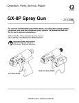
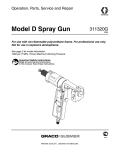
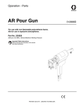
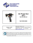
Operation, Parts, Service and Repair GAP Pro Spray Gun 311322K EN For use with non-flammable polyurethane foams. For professional use only. Not for use in explosive atmospheres. See page 3 for model information. 3000 psi (20.7 MPa, 207 bar) Maximum Working Fluid Pressure 125 psi (0.86 MPa, 8.6 bar) Maximum Working Air Pressure Important Safety Instructions Read all warnings and instructions in this manual. Save these instructions. Contents Gun Models . . . . . . . . . . . . . . . . . . . . . . . . . . . . . . . 3 Warnings . . . . . . . . . . . . . . . . . . . . . . . . . . . . . . . . . 4 Overall View . . . . . . . . . . . . . . . . . . . . . . . . . . . . . . . 6 Major Components . . . . . . . . . . . . . . . . . . . . . . . 6 Operation . . . . . . . . . . . . . . . . . . . . . . . . . . . . . . . . . 8 Isocyanate Hazard . . . . . . . . . . . . . . . . . . . . . . . 8 Keep A and B Components Separate . . . . . . . . . 8 Grounding . . . . . . . . . . . . . . . . . . . . . . . . . . . . . . 8 Safety Stop . . . . . . . . . . . . . . . . . . . . . . . . . . . . . 9 Manual Valves . . . . . . . . . . . . . . . . . . . . . . . . . . . 9 Air Hose Configurations . . . . . . . . . . . . . . . . . . 10 Initial Set Up . . . . . . . . . . . . . . . . . . . . . . . . . . . 11 Daily Start-Up . . . . . . . . . . . . . . . . . . . . . . . . . . 11 Daily Shutdown . . . . . . . . . . . . . . . . . . . . . . . . . 11 Pressure Relief Procedure . . . . . . . . . . . . . . . . 12 Grease Gun . . . . . . . . . . . . . . . . . . . . . . . . . . . 12 Repair . . . . . . . . . . . . . . . . . . . . . . . . . . . . . . . . . . . 13 Side Blocks . . . . . . . . . . . . . . . . . . . . . . . . . . . . 13 Mixing Chamber and Gun Block . . . . . . . . . . . . 15 End Cap and Air Piston . . . . . . . . . . . . . . . . . . . 17 End Cap O-ring and Safety Stop Seal . . . . . . . 19 Trigger/Air Valve . . . . . . . . . . . . . . . . . . . . . . . . 21 Air Passage Diagrams . . . . . . . . . . . . . . . . . . . . 23 Parts . . . . . . . . . . . . . . . . . . . . . . . . . . . . . . . . . . . . 26 GAP Pro Spray Gun Assembly . . . . . . . . . . . . . 26 GAP Pro Spray Gun Handle Assembly . . . . . . . 28 Accessories . . . . . . . . . . . . . . . . . . . . . . . . . . . . 30 Technical Data . . . . . . . . . . . . . . . . . . . . . . . . . . . . 31 Graco Standard Warranty . . . . . . . . . . . . . . . . . . . 32 Graco Information . . . . . . . . . . . . . . . . . . . . . . . . . 32 2 311322K Gun Models Gun Models Part No. Description Mix Module 295557 Round Pattern Gun #00 round 295558 Round Pattern Gun, Recirculating #00 round 295559 Round Pattern Gun #01 round 295560 Round Pattern Gun #02 round 295561 Round Pattern Gun #03 round 295562 Round Pattern Gun #04 round 311322K 3 Warnings Warnings The following general warnings are for the setup, use, grounding, maintenance, and repair of this equipment. Additional, more specific warnings may be found throughout the body of this manual where applicable. Symbols appearing in the body of the manual refer to these general warnings. When these symbols appear throughout the manual, refer back to these pages for a description of the specific hazard. WARNING PERSONAL PROTECTIVE EQUIPMENT You must wear appropriate protective equipment when operating, servicing, or when in the operating area of the equipment to help protect you from serious injury, including eye injury, inhalation of toxic fumes, burns, and hearing loss. This equipment includes but is not limited to: • Protective eyewear • Clothing and respirator as recommended by the fluid and solvent manufacturer • Gloves • Hearing protection TOXIC FLUID OR FUMES HAZARD Toxic fluids or fumes can cause serious injury or death if splashed in the eyes or on skin, inhaled, or swallowed. • Read MSDS’s to know the specific hazards of the fluids you are using. • Store hazardous fluid in approved containers, and dispose of it according to applicable guidelines. SKIN INJECTION HAZARD High-pressure fluid from gun, hose leaks, or ruptured components will pierce skin. This may look like just a cut, but it is a serious injury that can result in amputation. Get immediate surgical treatment. • Do not point gun at anyone or at any part of the body. • Do not put your hand over the spray tip. • Do not stop or deflect leaks with your hand, body, glove, or rag. • Do not spray without tip guard and trigger guard installed. • Follow Pressure Relief Procedure in this manual, when you stop spraying and before cleaning, checking, or servicing equipment. PRESSURIZED EQUIPMENT HAZARD Fluid from the gun/dispense valve, leaks, or ruptured components can splash in the eyes or on skin and cause serious injury. • Follow Pressure Relief Procedure in this manual, when you stop spraying and before cleaning, checking, or servicing equipment. • Tighten all fluid connections before operating the equipment. • Check hoses, tubes, and couplings daily. Replace worn or damaged parts immediately. 4 311322K Warnings WARNING FIRE AND EXPLOSION HAZARD Flammable fumes, such as solvent and paint fumes, in work area can ignite or explode. To help prevent fire and explosion: • Use equipment only in well ventilated area. • Eliminate all ignition sources; such as pilot lights, cigarettes, portable electric lamps, and plastic drop cloths (potential static arc). • Keep work area free of debris, including solvent, rags and gasoline. • Do not plug or unplug power cords, or turn power or light switches on or off when flammable fumes are present. • Ground all equipment in the work area. See Grounding instructions. • Use only grounded hoses. • Hold gun firmly to side of grounded pail when triggering into pail. • If there is static sparking or you feel a shock, stop operation immediately. Do not use equipment until you identify and correct the problem. • Keep a fire extinguisher in the work area. EQUIPMENT MISUSE HAZARD Misuse can cause death or serious injury. • Do not operate the unit when fatigued or under the influence of drugs or alcohol. • Do not exceed the maximum working pressure or temperature rating of the lowest rated system component. See Technical Data in all equipment manuals. • Use fluids and solvents that are compatible with equipment wetted parts. See Technical Data in all equipment manuals. Read fluid and solvent manufacturer’s warnings. For complete information about your material, request MSDS forms from distributor or retailer. • Check equipment daily. Repair or replace worn or damaged parts immediately with genuine Graco/Gusmer replacement parts only. • Do not alter or modify equipment. • Use equipment only for its intended purpose. Call your Graco/Gusmer distributor for information. • Route hoses and cables away from traffic areas, sharp edges, moving parts, and hot surfaces. • Do not kink or over bend hoses or use hoses to pull equipment. • Keep children and animals away from work area. • Comply with all applicable safety regulations. PRESSURIZED ALUMINUM PARTS HAZARD Do not use 1,1,1-trichloroethane, methylene chloride, other halogenated hydrocarbon solvents or fluids containing such solvents in pressurized aluminum equipment. Such use can cause serious chemical reaction and equipment rupture, and result in death, serious injury, and property damage. 311322K 5 Overall View Overall View Major Components Safety Stop A-Manual Valve A-Screen Screw R-Manual Valve Spray Tip R-Screen Screw Trigger FIG. 1. Major Components (shown with round spray tip) 6 311322K Overall View O-Ring R-Side Block Mixing Chamber Gun Block 2 Air Cap Flat Tip ! Air Seal Gun Block Screws Side Block Screws A-Side Block FIG. 2. Front End Components (shown with flat spray tip assembly) 311322K 7 Operation Operation Grounding To prevent accidental gun operation, always disconnect air supply before servicing gun or anytime gun is not in use. Isocyanate Hazard Spraying materials containing isocyanates creates potentially harmful mists, vapors, and atomized particulates. Check your local electrical code and proportioner manual for detailed grounding instructions. Ground the spray gun through connection to a Graco-approved grounded fluid supply hose. Read material manufacturer’s warnings and material MSDS to know specific hazards and precautions related to isocyanates. Prevent inhalation of isocyanate mists, vapors, and atomized particulates by providing sufficient ventilation in the work area. If sufficient ventilation is not available, a supplied-air respirator is required for everyone in the work area. To prevent contact with isocyanates, appropriate personal protective equipment, including chemically impermeable gloves, boots, aprons, and goggles, is also required for everyone in the work area. Keep A and B Components Separate CAUTION To prevent cross-contamination of the gun’s wetted parts, do not interchange A component (isocyanate) and B component (resin) parts. The gun is shipped with the A side on the left. 8 311322K Operation Safety Stop Manual Valves Manual valves located on the side blocks control flow of each chemical component to gun. Always engage safety stop, close both manual valves, and disconnect air before cleaning, maintaining, or repairing gun, or any time gun is not in use. The GAP Pro gun has a 2-position safety stop. When engaged, it prevents accidental triggering of gun. When disengaged, it allows gun to dispense. 1. To engage the safety stop, push in and turn the safety stop knob clockwise. See FIG. 3. Triggering gun with manual valves closed may cause crossover if gun ports contain residual chemical. Always engage safety stop, close both manual valves, and disconnect air before cleaning, maintaining, or repairing gun, or any time gun is not in use. Never open a manual valve unless side block is secured to gun or exit port is directed into flush pail. 1. Open manual valves using a 5/16 in. nut driver; turn manual valves counterclockwise approximately three full turns. FIG. 3. Engage Safety Stop 2. Close manual valves by turning fully clockwise. Manual Valves 2. To disengage the safety stop, push in and turn the safety stop knob counterclockwise. See FIG. 4. 2 ! Coupling Blocks FIG. 4. Disengage Safety Stop FIG. 5. Manual Valves 311322K 9 Operation Air Hose Configurations The GAP Pro Gun has two possible air hose configurations. In the standard configuration, the air connection is at the base of the handle. In the optional configuration, the air connection is at the rear of the gun. 1. See FIG. 6. Remove air hose from nipple at base of gun handle. 2. Remove nipple from gun handle. 3. Remove pipe plug from back of gun. 4. Install pipe plug in base of gun handle. 5. Install nipple in back of gun. Always engage safety stop, close both manual valves, and disconnect air before changing air hose configuration. 6. Connect air hose to nipple and use wrench to tighten. Install Pipe Nipple Air Hose 2 Remove Pipe Plug ! Install Pipe Plug Remove Long Pipe Nipple FIG. 6. Air Hose Configuration 10 311322K Operation Initial Set Up Daily Start-Up 1. Close both manual valves. Ensure side blocks are attached to gun, and proportioning unit is at desired temperature and pressure. 2. Engage safety stop. 3. Install female quick disconnect fitting on air hose, which is bundled with fluid supply hoses. 4. Connect A-isocyanate hose (red-taped) to fitting on A-side block. Then connect R-resin hose (blue-taped) to fitting on R-side block. 1. Connect air supply to gun, page 10. 2. Trigger gun multiple times to ensure proper mixing chamber movement. 3. Open both manual valves, page 9. 4. Disengage safety stop. 5. Test spray on disposable surface. A and R side hoses are sized differently to prevent improper connection. Daily Shutdown 5. Pressurize A and R chemical hoses and check for leaks. (See Proportioning Unit manual.) 6. Check proportioning unit for proper hose temperature, heater temperature, and pressure. (See Proportioning Unit manual.) 7. Connect air supply hose to gun. 8. Open both manual valves, page 9. 9. Disengage safety stop. 10. Test spray on disposable surface. 11. Proceed with Daily Start-up procedure or Shutdown procedure as required. 311322K Follow this procedure when gun is out of service for any length of time. Daily disassembly of gun for cleaning is not recommended if it has been operating properly. However, if you remove gun from coupling block, flush and clean thoroughly. 1. Follow Pressure Relief Procedure, page 12. 2. Shutdown proportioning unit as required. 3. Grease gun, page 12. 11 Operation Pressure Relief Procedure Grease Gun Do not grease gun if gun will be serviced following shutdown. Relieve pressure before cleaning or repairing gun. 1. Close both manual valves. 2. Engage safety stop. 3. Trigger gun once onto waste area to relieve fluid pressure in gun front end. 4. Disconnect gun air supply, page 10. 1. Follow Pressure Relief Procedure, page 12. 2. Insert GAP Gun Chamber Lubricant Needle into nozzle of mixing chamber. Dispense a small amount of lubricant into mixing chamber. To determine correct amount of lubricant, remove air cap to view internal chamber area. When lubricant becomes visible, stop dispensing. If fluid in hose and proportioner is still under pressure, follow Pressure Relief Procedure in proportioner manual. 3. Connect gun air supply. To relieve pressure in hose after gun is removed, place fluid manifold over containers, facing away from you. Very carefully open fluid valves. Under high pressure, fluid will spray sideways from fluid ports. 5. Disconnect gun air supply, page 10. 12 4. With safety stop engaged, trigger gun 2 or 3 times to discharge any excess lubricant. 311322K Repair Repair 2. See FIG. 7. Remove A-side screen screw, seal, and screen. Inspect for damage. Thoroughly rinse and dry screen. Hold screen up to a bright light; mesh must be free of particles and material buildup. Replace as necessary. Repeat for R-side. Shutdown proportioner and allow chemicals to cool before performing any repair procedures. 3. Alternately loosen side block mounting screws. Carefully separate side blocks from gun. Wipe mating surfaces with a rag soaked in gun cleaner. Side Blocks 4. Remove check valve retainer/side seal assembly from A-side block. 1. Follow Pressure Relief Procedure, page 12. Manual Valve Assembly Side Block Screen Screw Seal Check Valve Assembly 2 Spring Check Valve Retainer Side Seal O-Ring Screen Screw Screen Side Seal Assembly Swivel Fitting FIG. 7. Side Block Components 311322K 13 Repair 5. Remove check valve and clean with gun cleaner. Inspect and replace if damaged. CAUTION Clean side seals with a wooden or plastic scraper or a brass brush. Do not use a pocketknife, razor blade, or any tool that may scratch surface. 6. Remove side seal and o-ring. Replace if damaged. 7. Clean all components thoroughly. Use brass brushes or drill bits to remove residual chemical from the gun block. Thorough cleaning ensures unrestricted movement of mixing chamber. Use cotton swabs soaked in gun cleaner if necessary. 10. Check side seal for wear by measuring how far seal protrudes from side seal assembly insert. A worn side seal promotes chemical leakage. Replace side seal if it protrudes 0.065 in. (1.65 mm) or less. In addition, check seal for scratches, which also promote leakage. See FIG. 9. 11. Inspect check valve assembly for damage by measuring gap between mating surface of side block and bottom edge of side seal assembly insert. If gap measures 0.018 in. (.46 mm) or less, the check valve assembly has been crushed due to overtightening and it must be replaced. See FIG. 9. .065 in. (1.65 mm) 8. Repeat steps 4-7 for R-side block. CAUTION Do not overtighten check valve retainer. Tightening more than 1/4 turn can damage check valve or retainer and cause leaking when gun is pressurized. .018 in. (0.46 mm) FIG. 9: Side Seal 12. Place spring in check valve retainer. 9. Place check valve assembly in check valve retainer and thread into side block finger tight. Use a 1/2 in. wrench to tighten retainer 1/4 turn and no more. See FIG. 8. 13. Lightly coat o-ring with grease and install on side seal. 14. Push side seal into the check valve retainer until o-ring engages detent groove and remains in place. 15. Install side blocks to gun body with two mounting screws. Tighten screws alternately and evenly to prevent leakage. One quarter of a full turn (max.) 16. Return gun to service. See Daily Start-Up, page 11. FIG. 8. Tighten Check Valve Retainer 14 311322K Repair Mixing Chamber and Gun Block 1. Follow Pressure Relief Procedure, page 12. 8. Slide gun block over mixing chamber and up to gun. Install two mounting screws. Tighten screws alternately and evenly to prevent leakage. 9. Install side blocks to gun body with two mounting screws. Tighten screws alternately and evenly to prevent leakage. 10. Return gun to service. See Daily Start-Up, page 11. If your gun has a round pattern spray tip, skip step 2 and go to step 3. 2. Remove flat tip assembly from end of mix module. 3. Remove air cap. 4. Use a 5/16 in. nut driver to alternately loosen side block mounting screws. Carefully separate side blocks from gun. Wipe mating surfaces with a rag soaked in gun cleaner. To repair side blocks, see Side Blocks, page 13. 5. Remove gun block bolts. Slide gun block away from gun. Wipe mating surfaces with a rag soaked in gun cleaner. Clean gun block with gun cleaner and brass brushes to remove residual chemical and built-up material. This ensures unrestricted movement of mixing chamber. 6. Use a 3/16 in. wrench or needle-nose pliers to hold end of piston shaft while unscrewing mixing chamber by hand. Clean mixing chamber with gun cleaner and drill bits. Inspect for damage and replace if necessary. 7. Hold end of piston shaft with a 3/16 in. wrench or needle-nose pliers. Screw mixing chamber onto shaft by hand. 311322K 15 Repair O-Ring R-Side Block Mixing Chamber Gun Block 2 Air Cap Flat Tip ! Air Seal Gun Block Screws Side Block Screws A-Side Block FIG. 10. Mixing Chamber and Gun Block 16 311322K Repair End Cap and Air Piston To repair gun block, see Mixing Chamber and Gun Block, page 15. 1. Follow Pressure Relief Procedure, page 12. 2. Use a 5/16 in. nut driver to alternately loosen side block mounting screws. Carefully separate side blocks from gun. Wipe mating surfaces with a rag soaked in gun cleaner. 4. See FIG. 11. Use a 3/16 in. wrench or needle-nose pliers to hold end of piston shaft while unscrewing mixing chamber by hand. To repair mixing chamber, see Mixing Chamber and Gun Block, page 15. 5. Disengage safety stop. 6. Use a 9/64 in. ball point hex key to remove socket head screw and clamp from rear of air cylinder. To repair side blocks, see Side Blocks, page 13. 3. Use a 5/16 in. nut driver to remove gun block mounting screws. Slide gun block away from gun. Wipe mating surfaces with a rag soaked in gun cleaner. Be sure to retain o-ring located between gun block and mounting flange. 7. Use a retaining ring pliers to remove retaining ring. Ring retains end cap position in air cylinder. Piston Assembly Piston Spring Mixing Chamber End Cap/Safety Stop Assembly Socket Head Cap Screw Retaining Ring Cylinder Clamp FIG. 11. End Cap and Piston Assembly 311322K 17 Repair Removing safety stop and end cap requires some force because o-ring is tightly compressed. 8. Pull safety stop until it and attached end cap come free from air cylinder. Be sure to retain piston spring, located inside cylinder. 9. Inspect end cap o-ring and remove if damaged. Lightly coat new o-ring with Lubriplate grease and install on end cap. 10. Pull piston assembly out of air cylinder. 11. See FIG. 12. Remove retaining ring and slide piston shaft out from the back of piston. 12. Inspect shaft and piston o-rings and replace if damaged. Lightly coat new o-rings with Lubriplate grease before installing. 13. Slide piston shaft into the back of piston, being careful not to damage shaft o-rings. Secure with retaining ring. 14. Install piston assembly into the air cylinder. See FIG. 11. Be sure to insert retaining ring completely into groove so end cap will remain in air cylinder when gun is pressurized. Keep clear of end cap when reapplying air pressure or triggering gun after reassembly in case of improper retaining ring installation 15. Center piston spring over raised portion of piston. Align raised portion of end cap with inside diameter of piston spring. Insert end cap into air cylinder. Press end cap until it moves past the undercut groove in air cylinder, which is where retaining ring nests. Maintain pressure on end cap, ensure groove remains visible, and install retaining ring using retaining ring pliers. 16. Reinstall socket head screw and cylinder clamp in rear of air cylinder. 17. Hold end of piston shaft with a 3/16 in. wrench or needle-nose pliers. Screw the mixing chamber onto shaft by hand. Piston Shaft 18. Slide gun block over mixing chamber and up to gun. Install two mounting screws. Tighten screws alternately and evenly to prevent leakage. Retaining Ring Piston Shaft O-Rings Piston 19. Install side blocks to gun body with two mounting screws. Tighten screws alternately and evenly to prevent leakage. 20. Return gun to service. See Daily Start-Up, page 11. Piston O-Ring FIG. 12. Piston Assembly 18 311322K Repair End Cap O-ring and Safety Stop Seal 3. Remove socket head screw and clamp from rear of air cylinder. 4. See FIG. 13. Use a retaining ring pliers to remove retaining ring. Ring retains end cap position in air cylinder. 1. Follow Pressure Relief Procedure, page 12. 2. Use a 5/16 in. nut driver to alternately loosen side block mounting screws. Carefully separate side blocks from gun. Wipe mating surfaces with a rag soaked in gun cleaner. To repair side blocks, see Side Blocks, page 13. Removing safety stop and end cap requires some force because o-ring is tightly compressed. 5. Pull safety stop until it and attached end cap come free from air cylinder. Be sure to retain piston spring, which is located inside cylinder. 6. Inspect end cap o-ring and replace if damaged. Lightly coat new o-ring with Lubriplate grease and install on end cap. End Cap/Safety Stop Assembly Retaining Ring Cylinder Clamp Socket Head Cap Screw FIG. 13. End Cap Assembly 311322K 19 Repair 7. See FIG. 14. Use a 5/64 in. hex key to loosen two setscrews on stop knob. Slide knob off shaft of stop pin. Retain shaft spring. Pull stop pin out of end cap. 8. Remove u-cup seal from end cap and replace if damaged. Lightly coat new seal with Lubriplate grease before installing; u-cup lips must face the air cylinder. 9. Insert stop pin into end cap. Slide shaft spring and stop knob onto shaft of stop pin. Use a 5/64 in. hex key to install two set screws in stop knob. Ensure knob set screws are aligned to flats on stop pin and tighten securely. Stop Knob Stop Spring Be sure to insert retaining ring completely into groove to ensure end cap remains in air cylinder when gun is pressurized. Keep clear of end cap when reapplying air pressure or triggering gun after reassembly in case of improper retaining ring installation 10. Center piston spring over raised portion of piston. Align raised portion of end cap with inside diameter of piston spring. Insert end cap into air cylinder. Press end cap until it moves past undercut groove in air cylinder, which is where retaining ring nests. Maintain pressure on end cap, ensure groove remains visible, and install retaining ring using retaining ring pliers. See FIG. 13. 11. Reinstall socket head screw and cylinder clamp in rear of air cylinder. End Cap 12. Install side blocks to gun body with two mounting screws. Tighten screws alternately and evenly to prevent leakage. Stop Pin Set Screws Cup Seal 13. Return gun to service. See Daily Start-Up, page 11. End Cap O-Ring FIG. 14. Safety Stop Assembly 20 311322K Repair Trigger/Air Valve seat until valve liner and seat are pushed out of valve cavity. 10. Inspect the four o-rings on valve liner and replace if necessary. Apply Lubriplate grease liberally to o-rings before installing. 1. Follow Pressure Relief Procedure, page 12. 2. Use a 5/16 in. nut driver to alternately loosen side block mounting screws. Carefully separate side blocks from gun. Wipe mating surfaces with a rag soaked in gun cleaner. To repair side blocks, see Side Blocks, page 13. 3. If gun is configured with air inlet at base of handle (standard), remove 1/8 npt pipe plug at rear of gun. If gun is configured with air inlet at rear, remove air hose and nipple. 4. Remove screw and locknut holding trigger lever in place. Remove trigger lever. 5. Remove valve retainer hex nut, which holds brass valve spool in place. 6. Carefully grip end of valve spool with a pliers and remove it. Valve spring, which fits into spool, will come out with it. Be careful not to lose spring. 7. Inspect spool o-rings and replace if damaged. Liberally coat new o-rings with Lubriplate grease before installing. 8. Remove 1/16 npt pipe plug from deep in port at rear of gun. 11. Ensure that valve cavity is free of debris. Apply a thin film of Lubriplate grease inside cavity. 12. Slide spring seat into cavity, tapered end first. Ensure it bottoms out in cavity. 13. There will be some resistance from the o-rings when installing valve liner. Push valve liner into cavity until 2 or 3 of the cavity’s internal threads are visible. Threads allow engagement with valve retainer nut, which aligns valve liner and spool to proper depth. 14. Apply a small amount of thread sealant to 1/16 npt pipe plug and reinstall. This seals threads to prevent air leaks. 15. Reinstall 1/8 npt pipe plug, or nipple and air hose, at rear of gun. 16. Ensure that valve spring is in place, and insert valve spool into valve liner. Screw in valve retainer nut until snug. Do not overtighten. 17. Reinstall trigger lever, screw, and locknut. 18. Install side blocks to gun body with two mounting screws. Tighten screws alternately and evenly to prevent leakage. 19. Return gun to service. See Daily Start-Up, page 11. 9. Brass spring seat is visible inside port at rear of gun. Use a 1/4 in. diameter (maximum) punch and hammer to gently tap 311322K 21 Repair Optional Air Hose and Nipple 1/8 in. Pipe Plug 1/16 in. Pipe Plug Spring Seat Valve Liner O-Rings Valve Spool Valve Spring Lock Nut Valve Retainer Nut Trigger Mounting Screw Trigger Lever FIG. 15. Trigger/Air Valve Assembly 22 311322K Repair Air Passage Diagrams Use thread sealant when reinstalling any threaded components. In addition, reinstall all set screws flush to outside surface of gun handle. .250 dia. .3125 dia. .375 dia. 1.858 dia. .687 dia. 1.750 dia. .3125 dia. 8-32 UNC-GH3 TAP 1/8 in. drill 1/8 in. drill 5/32 in. drill 8-32 UNC-2B TAP FIG. 16: Air Cylinder Air Passages 311322K 23 Repair 1/8 in. drill 10-32 UNC-2B TAP 1/8 in. drill 5/32 in. drill 1/8 in. drill 10-32 UNC-2B TAP 5/32 in. drill 10-32 UNC-2B TAP 5/32 in. drill 1/8 in. drill 10-32 UNC-2B TAP 5/32 in. drill (3) 10-32 UNC-2B TAP 5/32 in. drill 1/2 in. dia. 5/8-18 UNC-2B TAP 1/8 in. NPT TAP 1/16 in. NPT TAP 5/32 in. drill 1/8 in. drill 1/8 NPT TAP FIG. 17: Handle Air Passages 24 311322K Repair Notes 311322K 25 Parts Parts GAP Pro Spray Gun Assembly 9 16 1 19 31 2 18 22 13 15 14 26 27 29 1 7 23 11 Round Spray 12 8 28 28 33 29 20 34 32 21 9 23 26 2 14 ! 35 31 27 15 13 3, 42 6 16 17 19 2 4 5 10 FIG. 18: GAP Pro Final Assembly 26 311322K Parts GAP Pro Spray Gun Assembly Ref. No. Part No. 1 117634 2 117635 3 15B772 4 5 6 7 8 9 10 11 12 13 14 15 16 295596 295597 296964 115719 296963 296970 103656 296952 296960 296953 296957 296959 296939 17 18 19 296940 296941 296942 Description Qty. FITTING, R-swivel 1 FITTING, A-swivel 1 HOSE, air; 1/4 npt (fbe) x 1 23 in. (584 mm) PLUG, coupler 1 COUPLER 1 BOLT, side block (pack of 2) O-RING, fluoroelastomer 1 BOLT, gun block (pack of 2) VALVE ASSEMBLY, manual 2 NIPPLE, hex; brass; 1/8 npt 1 BLOCK, gun 1 HANDLE, gun 1 CHECK VALVE ASSEMBLY 2 RETAINER, check valve 2 SPRING (pack of 2) SCREEN; 80 mesh (pack of 10) SCREW, screen, A-side 1 SCREW, screen, R-side 1 SEAL, screw, screen (pack of 2) Ref. No. Part No. 20 295693 21 296965 22 296966 23 248128 Description Qty. PLUG, seal, flush; 1/16 npt 2 BLOCK, A-side 1 BLOCK, R-side 1 O-RING, side seal 2 (pack of 6) SEAL, side 2 MIXING CHAMBER 1 SEAL, air 1 CAP, air 1 FITTING, straight 4 PLUG or ELBOW 2 TOOL, cleanout 1 TOOL, cleanout 1 100030 Fitting 1 26 27 28 29 30 31 40 41 42 See Table 1 for part numbers by model. Table 1: Round Pattern Guns, Parts by Model Number Round Pattern Gun Model No. Ref. No. 295557 295558 295559 295560 295561 295562 (00 Round) (00 Recirc) (01 Round) (02 Round) (03 Round) (04 Round) 26 27 28 29 31 40 41 296956 296846† 296946 296951 295662 118369 296289 296956 296846† 296946 296951 112307 118369 296289 296956 296847† 296946 296951 295662 296293 296296 296956 296848† 296946 296951 295662 118369 296297 296956 296849† 296946 296951 295662 296296 296302 296956 296850† 296946 296487 295662 296297 296490 This model uses qty. 2 each of items 1 and 2. Kit includes qty. 2 each of items 23 and 26. † Kit includes (1) 27, (1) 28, and cleanout tools 40 and 41. 311322K 27 Parts GAP Pro Spray Gun Handle Assembly 70 77 66 75 76 51 78 79 84 62 82 55 85 63 57 81 59 52 65 67 53 57 74 64 57 56 57 72 83 68 71 73 60 86 80 61 58 54 69 FIG. 19: GAP Pro Handle Assembly 28 311322K Parts GAP Pro Spray Gun Handle Assembly Ref. No. Part No. 51 295435 52 295422 53 296537 54 106245 55 296536 56 295662 57 C20988 58 112085 59 103337 60 C02032 61 295692 62 116624 63 102279 64 296971 65 296535 66 108103 67 168518 68 295695 69 295671 311322K Description SEAL, u-cup RING, retaining SCREW, cap, socket hd SCREW, cap, socket hd SCREW, set; socket hd PLUG, pipe O-RING O-RING O-RING NUT TRIGGER SCREW, set; socket hd SCREW, set; socket hd SPRING CLAMP, cylinder O-RING O-RING SCREW, cap; button hd SCREW, trigger Qty. 1 1 1 2 1 1 6 4 1 1 1 2 2 1 1 1 1 1 1 Ref. No. Part No. 70 296538 71 296866 72 296527 73 296867 74 295434 75 295436 76 296529 77 296530 78 296526 79 295416 80 296961 81 296531 82 296937 83 295693 84 296962 85 114054 86 295665 Description RING, retaining LINER, valve SPOOL, valve NUT, retainer, valve SEAT, spring SPRING CAP, end KNOB PIN, stop SPRING, piston HANDLE, gun PISTON SHAFT, piston PLUG, pipe CYLINDER, air O-RING NIPPLE Qty. 1 1 1 1 1 1 1 1 1 1 1 1 1 1 1 1 1 Included in Handle Seal Repair Kit 296938 (purchase separately). 29 Parts Accessories Tool kit 296968 for GAP Pro spray gun. Pour Package (296983) Components Grease syringe 296382; syringe filled with grease for gun maintenance. Includes: Pour fitting Polyflow tubing (3/8 in. diameter x 1 ft. length) Gun Wand Kit Kit 296984; extends GAP spray gun front-end 21 in. 297078 296165 1 1 27 (flat mix chamber required) 28 29 (flat air cap required) FIG. 20: Pour Package Components Mixing Chamber Cleanout Drills 30 Round Mixing Chamber (27) Mixing Chamber Nozzle Cleanout Drill Mixing Chamber Port Cleanout Drill 296846 118369 296289 296847 296296 296293 296848 296297 118369 296849 296302 296296 296850 296490 296297 296851 296491 296302 311322K Technical Data Technical Data Category Maximum Fluid Working Pressure Minimum Air Inlet Pressure Maximum Air Inlet Pressure Maximum Output (flow rate) Air Inlet Size A Component (ISO) Inlet Size R Component (Resin) Inlet Size Length Height Width Weight Wetted Parts 311322K Data 3000 psi (20.7 MPa, 207 bar) 100 psi (0.7 MPa, 7 bar) 125 psi (0.9 MPa, 9 bar) 40 lb/min (18 kg/min) 1/8 npt -5 JIC; 1/2-20 UNF -6 JIC; 9/16-18 UNF 7 in. (17.8 cm) 7.25 in. (18.4 cm) 4.4 in. (11.2 cm) 2.34 lb (1.06 kg) Stainless steel, carbon steel, brass, nylon, acetal, PTFE, aluminum 31 Graco Standard Warranty Graco Standard Warranty Graco warrants all equipment referenced in this document which is manufactured by Graco and bearing its name to be free from defects in material and workmanship on the date of sale to the original purchaser for use. With the exception of any special, extended, or limited warranty published by Graco, Graco will, for a period of twelve months from the date of sale, repair or replace any part of the equipment determined by Graco to be defective. This warranty applies only when the equipment is installed, operated and maintained in accordance with Graco’s written recommendations. This warranty does not cover, and Graco shall not be liable for general wear and tear, or any malfunction, damage or wear caused by faulty installation, misapplication, abrasion, corrosion, inadequate or improper maintenance, negligence, accident, tampering, or substitution of non-Graco component parts. Nor shall Graco be liable for malfunction, damage or wear caused by the incompatibility of Graco equipment with structures, accessories, equipment or materials not supplied by Graco, or the improper design, manufacture, installation, operation or maintenance of structures, accessories, equipment or materials not supplied by Graco. This warranty is conditioned upon the prepaid return of the equipment claimed to be defective to an authorized Graco distributor for verification of the claimed defect. If the claimed defect is verified, Graco will repair or replace free of charge any defective parts. The equipment will be returned to the original purchaser transportation prepaid. If inspection of the equipment does not disclose any defect in material or workmanship, repairs will be made at a reasonable charge, which charges may include the costs of parts, labor, and transportation. THIS WARRANTY IS EXCLUSIVE, AND IS IN LIEU OF ANY OTHER WARRANTIES, EXPRESS OR IMPLIED, INCLUDING BUT NOT LIMITED TO WARRANTY OF MERCHANTABILITY OR WARRANTY OF FITNESS FOR A PARTICULAR PURPOSE. Graco’s sole obligation and buyer’s sole remedy for any breach of warranty shall be as set forth above. The buyer agrees that no other remedy (including, but not limited to, incidental or consequential damages for lost profits, lost sales, injury to person or property, or any other incidental or consequential loss) shall be available. Any action for breach of warranty must be brought within two (2) years of the date of sale. GRACO MAKES NO WARRANTY, AND DISCLAIMS ALL IMPLIED WARRANTIES OF MERCHANTABILITY AND FITNESS FOR A PARTICULAR PURPOSE, IN CONNECTION WITH ACCESSORIES, EQUIPMENT, MATERIALS OR COMPONENTS SOLD BUT NOT MANUFACTURED BY GRACO. These items sold, but not manufactured by Graco (such as electric motors, switches, hose, etc.), are subject to the warranty, if any, of their manufacturer. Graco will provide purchaser with reasonable assistance in making any claim for breach of these warranties. In no event will Graco be liable for indirect, incidental, special or consequential damages resulting from Graco supplying equipment hereunder, or the furnishing, performance, or use of any products or other goods sold hereto, whether due to a breach of contract, breach of warranty, the negligence of Graco, or otherwise. FOR GRACO CANADA CUSTOMERS The Parties acknowledge that they have required that the present document, as well as all documents, notices and legal proceedings entered into, given or instituted pursuant hereto or relating directly or indirectly hereto, be drawn up in English. Les parties reconnaissent avoir convenu que la rédaction du présente document sera en Anglais, ainsi que tous documents, avis et procédures judiciaires exécutés, donnés ou intentés, à la suite de ou en rapport, directement ou indirectement, avec les procédures concernées. Graco Information For the latest information about Graco products, visit www.graco.com. TO PLACE AN ORDER, contact your Graco distributor or call to identify the nearest distributor. Phone: 612-623-6921 or Toll Free: 1-800-328-0211, Fax: 612-378-3505 32 311322K