1
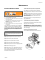
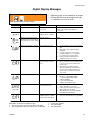
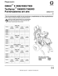
Repair
GMAX™ II 3900/5900/7900
TexSpray™ 5900HD/7900HD
Airless Sprayers
310893P
ENG
Korean patent: 10-0647761
- For Portable Airless Spraying of Architectural Coatings and Paints 3300 psi (22.8 MPa, 228 bar) Maximum Working Pressure
Important Safety Instructions
Read all warnings and instructions in
this manual. Save these instructions.
ti5475a
ti5447a
ti5474a
248683
248684
248685
248686
249335
248687
248688
248689
248690
249336
248699
248700
248701
248702
248703
249337
255632
GMAX ll 3900
✓
✓
✓
✓
✓
GMAX ll 5900
✓
✓
✓
✓
✓
TexSpray 5900HD
✓
GMAX ll 7900
✓
✓
✓
✓
✓
TexSpray 7900HD
✓
✓
✓
✓
✓
✓
✓
✓
✓
✓
✓
✓
✓
✓
✓
✓
✓
✓
Related Manuals
310892
311861
308491
310894
309640
Manual Conventions
Contents
WARNING . . . . . . . . . . . . . . . . . . . . . . . . . . . . . . . . . 3
Maintenance . . . . . . . . . . . . . . . . . . . . . . . . . . . . . . . 5
Troubleshooting . . . . . . . . . . . . . . . . . . . . . . . . . . . . 6
Repair . . . . . . . . . . . . . . . . . . . . . . . . . . . . . . . . . . . . 8
Bearing Housing & Connecting Rod . . . . . . . . . . . 8
Drive Housing . . . . . . . . . . . . . . . . . . . . . . . . . . . . . . 9
Pinion Assembly/Clutch Armature/Clamp . . . . . . 10
Clutch Housing . . . . . . . . . . . . . . . . . . . . . . . . . . . 12
Engine . . . . . . . . . . . . . . . . . . . . . . . . . . . . . . . . . . . 12
Pump ON/OFF Switch . . . . . . . . . . . . . . . . . . . . . . 13
Pressure Control . . . . . . . . . . . . . . . . . . . . . . . . . . 14
Displacement Pump . . . . . . . . . . . . . . . . . . . . . . . 16
Parts . . . . . . . . . . . . . . . . . . . . . . . . . . . . . . . . . . . . 20
GMAX II 3900 Parts Drawing . . . . . . . . . . . . . . . . . 20
GMAX II 5900/5900HD Parts Drawing . . . . . . . . . . 22
GMAX II 7900/TexSpray 7900HD Parts Drawing . . 24
Parts Drawing and List - Pinion Housing . . . . . . . 26
Lo-Boy Suction Set . . . . . . . . . . . . . . . . . . . . . . . . . 27
Pressure Control and Filter Parts Drawing. . . . . . 28
Parts - Sprayers, RAC X® Tip, Gun & Hose . . . . . . . . . . 30
Technical Data . . . . . . . . . . . . . . . . . . . . . . . . . . . . 31
Dimensions . . . . . . . . . . . . . . . . . . . . . . . . . . . . . . . 31
Graco Standard Warranty . . . . . . . . . . . . . . . . . . . 32
Manual Conventions
WARNING
Hazard Symbol
WARNING: a potentially hazardous situation which, if
not avoided, could result in death or serious injury.
Warnings in the instructions usually include a symbol
indicating the hazard. Read the general Warnings
section for additional safety information.
2
CAUTION
CAUTION: a potentially hazardous situation which, if
not avoided, may result in property damage or
destruction of equipment.
Note
Additional helpful information.
310893P
Warning
Warning
The following are general warnings related to the setup, use, maintenance and repair of this equipment. Additional,
more specific, warnings may be found throughout the text of this manual, where applicable.
WARNING
FIRE AND EXPLOSION HAZARD
Flammable fumes, such as solvent and paint fumes, in work area can ignite or explode. To help prevent
fire and explosion:
• Use equipment only in well ventilated area.
• Do not fill fuel tank while engine is running or hot; shut off engine and let it cool. Fuel is flammable
and can ignite or explode if spilled on hot surface.
• When flammable liquid is sprayed or used for flushing or cleaning, keep sprayer at least 20 feet (6 m)
away from explosive vapors.
• Eliminate all ignition sources; such as pilot lights, cigarettes, portable electric lamps, and plastic drop
cloths (potential static arc).
• Keep work area free of debris, including solvent, rags and gasoline.
• Do not plug or unplug power cords, or turn power or light switches on or off when flammable fumes
are present.
• Ground equipment and conductive objects in work area. See Grounding instructions.
• Use only grounded hoses.
• Hold gun firmly to side of grounded pail when triggering into pail.
• If there is static sparking or you feel a shock, stop operation immediately. Do not use equipment
until you identify and correct the problem.
SKIN INJECTION HAZARD
High-pressure fluid from gun, hose leaks, or ruptured components will pierce skin. This may look like just
a cut, but it is a serious injury that can result in amputation. Get immediate surgical treatment.
• Do not point gun at anyone or at any part of the body.
• Do not put your hand over the spray tip.
• Do not stop or deflect leaks with your hand, body, glove, or rag.
• Do not spray without tip guard and trigger guard installed.
• Engage trigger lock when not spraying.
• Follow Pressure Relief Procedure in this manual, when you stop spraying and before cleaning,
checking, or servicing equipment.
PRESSURIZED EQUIPMENT HAZARD
Fluid from the gun/dispense valve, leaks, or ruptured components can splash in the eyes or on skin and
cause serious injury.
• Follow Pressure Relief Procedure in this manual, when you stop spraying and before cleaning,
checking, or servicing equipment.
• Tighten all fluid connections before operating the equipment.
• Check hoses, tubes, and couplings daily. Replace worn or damaged parts immediately.
MOVING PARTS HAZARD
Moving parts can pinch or amputate fingers and other body parts.
• Keep clear of moving parts.
• Do not operate equipment with protective guards or covers removed.
• Pressurized equipment can start without warning. Before checking, moving, or servicing equipment,
follow the Pressure Relief Procedure in this manual. Disconnect power or air supply.
310893P
3
Warning
WARNING
EQUIPMENT MISUSE HAZARD
Misuse can cause death or serious injury.
• Do not exceed the maximum working pressure or temperature rating of the lowest rated system
component. See Technical Data in all equipment manuals.
• Use fluids and solvents that are compatible with equipment wetted parts. See Technical Data in all
equipment manuals. Read fluid and solvent manufacturer’s warnings.
• Check equipment daily. Repair or replace worn or damaged parts immediately.
• Do not alter or modify equipment.
• Do not install a shut-off device between filter outlet and gun.
• Use equipment only for its intended purpose. Call your Graco distributor for information.
• Route hoses and cables away from traffic areas, sharp edges, moving parts, and hot surfaces.
• Do not use hoses to pull equipment.
• Keep children and animals away from work area.
• Comply with all applicable safety regulations.
PRESSURIZED ALUMINUM PARTS HAZARD
Do not use 1,1,1-trichloroethane, methylene chloride, other halogenated hydrocarbon solvents or fluids
containing such solvents in pressurized aluminum equipment. Such use can cause serious chemical
reaction and equipment rupture, and result in death, serious injury, and property damage.
SUCTION HAZARD
Never place hands near the pump fluid inlet when pump is operating or pressurized. Powerful suction
could cause serious injury.
CARBON MONOXIDE HAZARD
Exhaust contains poisonous carbon monoxide, which is colorless and odorless. Breathing carbon monoxide can cause death. Do not operate in an enclosed area.
TOXIC FLUID OR FUMES HAZARD
Toxic fluids or fumes can cause serious injury or death if splashed in the eyes or on skin, inhaled, or
swallowed.
• Read MSDS’s to know the specific hazards of the fluids you are using.
• Store hazardous fluid in approved containers, and dispose of it according to applicable guidelines.
BURN HAZARD
Equipment surfaces and fluid that’s heated can become very hot during operation. To avoid severe
burns, do not touch hot fluid or equipment. Wait until equipment/fluid has cooled completely.
PERSONAL PROTECTIVE EQUIPMENT
You must wear appropriate protective equipment when operating, servicing, or when in the operating
area of the equipment to help protect you from serious injury, including eye injury, inhalation of toxic
fumes, burns, and hearing loss. This equipment includes but is not limited to:
• Protective eyewear
• Clothing and respirator as recommended by the fluid and solvent manufacturer
• Gloves
• Hearing protection
RECOIL HAZARD
Brace yourself; gun may recoil when triggered and cause you to fall, which could cause serious injury.
4
310893P
Maintenance
Maintenance
Pressure Relief Procedure
WARNING
Read Injection Hazard, page 3; Burn Hazard, page 4.
1.
2.
3.
4.
5.
6.
Lock gun trigger safety.
Turn engine ON/OFF switch to OFF.
Move pump switch to OFF and turn pressure control knob
fully counterclockwise.
Unlock trigger safety. Hold metal part of gun firmly to side
of grounded metal pail, and trigger gun to relieve
pressure.
Lock gun trigger safety.
Open pressure drain valve. Leave valve open until ready
to spray again.
If you suspect that the spray tip or hose is completely
clogged, or that pressure has not been fully relieved
after following the steps above, VERY SLOWLY loosen
tip guard retaining nut or hose end coupling to relieve
pressure gradually, then loosen completely. Now clear
tip or hose.
AFTER THE FIRST 20 HOURS OF OPERATION:
Drain engine oil and refill with clean oil. Reference
Honda Engines Owner's Manual for correct oil viscosity.
WEEKLY: Remove engine air filter cover and clean element. Replace element, if necessary. If operating in an
unusually dusty environment: check filter daily and
replace, if necessary.
Replacement elements can be purchased from your
local HONDA dealer.
AFTER EACH 100 HOURS OF OPERATION:
Change engine oil. Reference Honda Engines Owner's
Manual for correct oil viscosity.
SPARK PLUG: Use only BPR6ES (NGK) or W20EPR-U
(NIPPONDENSO) plug. Gap plug to 0.028 to 0.031 in.
(0.7 to 0.8 mm). Use spark plug wrench when installing
and removing plug.
Premium Sprayers Engine Oil Funnel:
Use the supplied engine oil funnel when draining oil.
CAUTION
For detailed engine maintenance and specifications,
refer to separate Honda Engines Owner's Manual,
supplied.
DAILY: Check engine oil level and fill as necessary.
DAILY: Check hose for wear and damage.
DAILY: Check that all hose fittings are secure.
ti6200a
DAILY: Check gun safety for proper operation.
DAILY: Check pressure drain valve for proper operation.
DAILY: Check and fill the gas tank.
DAILY: Check level of TSL in displacement pump packing nut. Fill nut, if necessary. Keep TSL in nut to help
prevent fluid buildup on piston rod and premature wear
of packings and pump corrosion.
310893P
OIL FUNNEL
5
Troubleshooting
Troubleshooting
Problem
E=XX is displayed
Engine will not start
False tripping of WatchDog system.
EMPTY is displayed. Pump does not
run.
Engine operates, but displacement
pump does not operate
Cause
Solution
Fault condition exists
Engine switch is OFF
Engine is out of gasoline
Determine fault correction from table, page 15
Turn engine switch ON
Refill gas tank. Honda Engines Owner's Manual.
Engine oil level is low
Try to start engine. Replenish oil, if necessary.
Honda Engines Owner's Manual.
Spark plug is disconnected or damaged Connect spark plug cable or replace spark plug
Cold engine
Use choke
Fuel shutoff lever is OFF
Move lever to ON position
Oil is seeping into combustion chamber Remove spark plug. Pull starter 3 to 4 times.
Clean or replace spark plug. Start engine.
Keep sprayer upright to avoid oil seepage
Operating conditions out of WatchDog Turn pressure down. Contact Graco Technical
parameters
Assistance to adjust WatchDog parameters.
Pump output is low, page 7.
Operate without WatchDog active; Manual
310892.
Error code displayed
Reference Pressure Control repair, page 15
Pump switch is OFF
Turn pump switch ON
Pressure setting too low
Turn pressure adjusting knob clockwise to
increase pressure.
Fluid filter (56) is dirty
Clean filter. Page 28.
Clean tip or tip filter. Manual 309639.
Tip or tip filter is clogged
Displacement pump piston rod is stuck Repair pump. Manual 310894.
due to dried paint
Connecting rod is worn or damaged
Replace connecting rod. Page 8.
Drive housing is worn or damaged
Replace drive housing. Page 9.
Electrical power is not energizing clutch Check wiring connections. Page 12.
field
Reference Digital Display Messages. Page 15.
Reference wiring diagram. Page 29.
With pump switch ON and pressure turned to MAXIMUM, use a test light to check for power between clutch
test points on control board.
Remove clutch wires from control board and
measure resistance across clutch coil. At 70° F,
the resistance must be between 1.2 +0.2Ω; if
not, replace pinion housing.
Have pressure control checked by authorized
Graco dealer
Clutch is worn, damaged, or incorrectly Adjust or replace clutch. Page 10.
positioned
Pinion assembly is worn or damaged
Repair or replace pinion assembly. Page10.
6
310893P
Troubleshooting
Problem
Pump output is low
Cause
Solution
Strainer (82) is clogged
Clean strainer.
Piston ball is not seating
Service piston ball. Manual 310894.
Piston packings are worn or damaged
Replace packings. Manual 310894.
O-ring in pump is worn or damaged
Replace o-ring. Manual 310894.
Intake valve ball is not seating properly
Clean intake valve. Manual 310894.
Intake valve ball is packed with material
Clean intake valve. Manual 310894.
Engine speed is too low
Increase throttle setting. Manual 310892.
Clutch is worn or damaged
Adjust or replace clutch. Page 10.
Pressure setting is too low
Increase pressure. Manual 310892.
Fluid filter (56), tip filter or tip is clogged or Clean filter. Manual 310892 or 309639.
dirty
Excessive paint leakage into throat
packing nut
Fluid is spitting from gun
Pump is difficult to prime
Large pressure drop in hose with heavy
materials
Use larger diameter hose and/or reduce
overall length of hose. Use of more than
100 ft of 1/4 in. hose significantly reduces
performance of sprayer. Use 3/8 in. hose
for optimum performance (50 ft minimum).
Throat packing nut is loose
Remove throat packing nut spacer. Tighten
throat packing nut just enough to stop leakage.
Throat packings are worn or damaged
Replace packings. Manual 310894.
Displacement rod is worn or damaged
Replace rod. Manual 310894.
Air in pump or hose
Check and tighten all fluid connections. Reprime pump. Manual 310892.
Tip is partially clogged
Clear tip. Manual 309639.
Fluid supply is low or empty
Refill fluid supply. Prime pump. Manual
310892. Check fluid supply often to prevent
running pump dry.
Air in pump or hose
Check and tighten all fluid connections.
Reduce engine speed and cycle pump as
slowly as possible during priming.
Intake valve is leaking
Clean intake valve. Be sure ball seat is not
nicked or worn and that ball seats well.
Reassemble valve.
Pump packings are worn
Replace pump packings. Manual 310894.
Paint is too thick
Thin the paint according to the supplier's
recommendations
Engine speed is too high
Decrease throttle setting before priming
pump. Manual 310892.
Clutch squeaks each time clutch
engages
Clutch surfaces are not matched to each other Clutch surfaces need to wear into each
when new and may cause noise
other. Noise will dissipate after a day of run
time.
High engine speed at no load
Misadjusted throttle setting
Reset throttle to 3300 engine rpm at no
load.
Worn engine governor
Replace or service engine governor
Gallon counter not working
Bad sensor, broken or disconnected wire. Check connections. Replace sensor or
Displaced or missing magnet.
wire. Reposition or replace magnet.
No display, sprayer operates
Display damaged or has bad connection
310893P
Check connections. Replace display.
7
Bearing Housing and Connecting Rod
Bearing Housing and Connecting Rod
NOTE: The item numbers referenced are for the 5900
Hi-Boy models. The 3900, 7900 and all Lo-Boy models
may have different item numbers. Use the 5900 Hi-Boy
item number and part to find the corresponding alternate part and item number.
Removal
WARNING
CAUTION
DO NOT use bearing housing screws (41) to align or
seat bearing housing with drive housing. Align these
parts with locating pins, to avoid premature bearing
wear.
5.
Install screws (41) and washers (42) in bearing housing.
Torque evenly to note 3 value in Fig. 1.
6.
Install pump. Refer to Displacement Pump, Installation,
page 14.
"
Read Injection Hazard, page 3; Burn Hazard, page 4
1.
Relieve pressure; page 5.
2.
FIG. 1. Remove four screws (45) and front cover (44)
3.
Remove pump. Refer to Displacement Pump, Removal,
page 16.
4.
Remove four screws (41) and washers (42) from bearing
housing (40).
5.
Pull connecting rod (43) and lightly tap lower rear of
bearing housing with plastic mallet to loosen from drive
housing (33). Pull bearing housing and connecting rod
assembly off drive housing.
6.
&
2.
Assemble connecting rod (43) to bearing housing (40).
Rotate connecting rod to lowest position.
3.
Clean mating surfaces of bearing and drive housings.
4.
Align connecting rod with crank (B) and carefully align
locating pins (F) in drive housing (33) with holes in
bearing housing (40). Push bearing housing onto drive
housing or tap into place with plastic mallet.
8
#
Inspect crank (B) and connecting rod (43) for excessive
wear and replace parts as needed.
Evenly lubricate inside of bronze bearing (C) in bearing
housing (40) with high-quality motor oil. Liberally pack top
roller bearing (E), lower bearing (D) inside connecting rod
(43) with bearing grease.
$
TIB
!
Installation
1.
%
1
2
3
Oil
Pack with bearing grease 114819
GMAX II 3900: Torque to 200 in-lb (22.6 N.m)
GMAX II 5900: Torque to 25 ft-lb (34 N.m)
GMAX II 7900: Torque to 40 ft-lb (54 N.m)
TexSpray 7900HD: Torque to 40 ft-lb (54 Nm
FIG. 1
310893P
Drive Housing
Drive Housing
Removal
CAUTION
DO NOT use drive housing screws (38) to align or seat
drive housing with pinion housing. Align these parts with
locating pins, to avoid premature bearing wear.
WARNING
8.
Install screws (38) in drive housing. Torque evenly to note
3 value in FIG. 2.
9.
Install pump. Refer to Displacement Pump, Installation,
page14.
Read Injection Hazard, page 3; Burn Hazard, page 4
1.
Relieve pressure; page 5.
2.
Remove bearing housing. Refer to Bearing Housing and
Connecting Rod, Removal, page 8.
"
CAUTION
TIA
A
Premium models: Gallon counter sensor is connected to control board in pressure control. Pulling on the sensor wires could
cause damage.
B
3.
Premium sprayers: Remove two screws (108) and gallon
counter sensor (39).
1
"
CAUTION
Thrust washers may stick to grease inside of drive housing.
Do not lose or misplace.
4.
Remove six screws (38).
5.
Lightly tap around drive housing (33) to loosen drive
housing. Pull drive housing straight off pinion housing. Be
prepared to support combination gear (32) which may
also come out.
FIG. 2. Apply all grease supplied with replacement gear
cluster to gear teeth and to areas called out by note 3.
2.
FIG. 3. Ensure thrust washers (30, 31; 5900/7900) (30, 31,
72; 3900) are on combination gear (32) and washers (Fig.
2; 33a, 33b) are on crankshaft of drive housing (33) as
shown.
3.
Clean mating surfaces of pinion and drive housings.
4.
Align gears and push new drive housing straight onto
pinion housing (29) and locating pins (B).
5.
Install six screws (38).
6.
Install gallon counter sensor (39) with two screws (108).
GMAX II 3900: Torque to 140 ±10 in-lb (15.8 ±1.1N.m)
GMAX II 5900: Torque to 200 ±10 in-lb (22.6 ±1.1 N.m)
GMAX II 7900: Torque to 200 ±10 in-lb (22.6 ±1.1 N.m)
Texspray 7900HD: Torque to 200 ±10 in-lb (22.6 ±1.1 N.m)
2
Gallon counter sensor
3 Pack with grease 114819
Installation
1.
1
FIG. 2
7.
Install bearing housing. Refer to Bearing Housing and
Connecting Rod, Installation, page 8.
310893P
1
Copper
2
Steel
TIA
FIG. 3
9
Pinion Assembly/Clutch Armature/Clamp
Pinion Assembly/Clutch Armature/Clamp
Pinion Assembly/Clutch Armature Removal
Pinion Assembly
28
24
If pinion assembly (29) is not removed from clutch housing
(19), do 1. through 3. Otherwise, start at 4.
29
E
E
WARNING
Read Injection Hazard, page 3; Burn Hazard, page 4
ti5481a
ti5987b
1.
Remove drive housing; page 9.
FIG. 5
2.
FIG. 4. Disconnect clutch cable connectors from inside of
pressure control.
a. FIG. 14. Remove two screws (71) and swing down
cover (130a).
b. Disconnect engine leads from board to engine.
c. Remove strain reliefs 130r and 123.
6.
FIG. 6. Remove retaining ring (29b).
7.
Turn pinion assembly over and tap pinion shaft (29a) out
with plastic mallet.
3.
27
FIG. 4. Remove four screws (36) and pinion assembly (29).
29b
36
37
29a
19
29
29d
ti5482a
FIG. 6
36
Clutch Armature
37
ti5480a
8.
FIG. 7. Use an impact wrench or wedge something
between clutch armature (25) and clutch housing to hold
engine shaft during removal.
9.
Remove four screws (23) and lock washers (24).
FIG. 4
4.
FIG. 5. Place pinion assembly (29) on bench with rotor
side up.
5.
Remove four screws (28) and lock washers (24). Install
two screws in threaded holes (E) in rotor. Alternately
tighten screws until rotor comes off.
10. Remove armature.
TIA
FIG. 7
10
310893P
Pinion Assembly/Clutch Armature/Clamp
Installation
Clutch Armature
1.
2.
3.
FIG. 8. Lay two stacks of two dimes on smooth bench
surface.
Lay armature (25) on two stacks of dimes.
Press center of hub (26) down to bench surface.
25
26
0.12+01 in (3.0+.25 mm)
ti6321a
dimes
FIG. 8
4.
Install armature (25) on engine drive shaft.
5.
Install four screws (23) and lock washers (24) with torque
of 125 in-lb.
Pinion Assembly
6. FIG. 6. Check o-ring (29d) and replace if missing or
damaged.
7. Tap pinion shaft (29a) in with plastic mallet.
8. Install retaining ring (29b) with beveled side facing up.
9. FIG. 5. Place pinion assembly on bench with rotor side up.
10. Apply thread sealant to screws. Install four screws (28)
and lock washers (24). Alternately torque screws to 125
in-lb until rotor is secure. Use threaded holes to hold rotor.
11. FIG. 4. Install pinion assembly (29) with four screws (36)
and washers (37).
12. FIG. 14. Connect clutch cable connectors to inside of
pressure control.
Clamp Removal
1.
Do Engine Removal.
1 Face of clutch housing
WARNING
2 1.550 ± .010 in. (39.37 ± .25 mm) - GMAX 3900
2.612 ± .010 in. (66.34 ± .25 mm) - GMAX 5900 & 7900
3 Torque to 125 ±.10 in-lb (14 ±1.1 N·m)
Gasoline can spill and cause a fire or explosion if
engine is tipped on side.
2.
3.
4.
5.
4 Chamfer this side
Drain gasoline from tank according to Honda manual.
FIG. 9. Tip engine on side so gas tank is down and air
cleaner is up.
FIG. 10. Loosen two screws (24) on clamp (22),
Push screwdriver into slot in clamp (22) and remove
clamp.
19
"
ti6199a
TIA
!
FIG. 9
Clamp Installation
1.
2.
3.
FIG. 10
FIG. 10. Install engine shaft key (18)
Tap clamp (22) onto engine shaft (A). Maintain dimension
shown note 2. Chamfer must face engine.
Check dimension: Place rigid, straight steel bar (B) across
face of clutch housing (19). Use accurate measuring
device to measure distance between bar and face of
clamp. Adjust clamp as necessary. Torque two screws
(24) to 125 ±10 in-lb (14 ±1.1 N·m)
310893P
11
Clutch Housing
Clutch Housing
Removal
1.
2.
3.
19
18
FIG. 11. Remove four screws (20) and lock washers (21)
which hold clutch housing (19) to engine.
Remove screw (35) from under mounting plate (D).
Pull off clutch housing (19).
Installation
1.
2.
3.
21
20
FIG. 11. Push on clutch housing (19).
Install four capscrews (20) and lock washers (21) and
secure clutch housing (19) to engine. Torque to 200 in-lb
(22.6 N·m).
Install screw (35) from beneath mounting plate (D).
Torque to 26 ft-lb (35.2 N·m).
D
ti5486a
35
FIG. 11
Engine
Removal
NOTE: All service to the engine must be performed by
an authorized HONDA dealer.
1.
2.
3.
4.
Remove Pinion Assembly/Clutch Armature/Clamp and
Clutch Housing, as instructed on pages 9, 10 and 11.
FIG. 12. Disconnect all necessary wiring.
FIG. 13. Remove two locknuts (17) and screws (16) from
base of engine.
Lift engine carefully and place on work bench.
1
To the field
2
3
16
To the engine
3
To gallon counter
4
To ground
ti5487a
17
1
FIG. 13
Bottom View
3900
Installation
Green
1.
2.
ti5485b
2
4
2
Bottom View
5900/7900
3.
4.
Lift engine carefully and place on cart.
FIG. 13. Install two screws (16) in base of engine and
secure with locknuts (17). Torque to 26 ft-lb (22.6 N·m).
FIG. 12. Connect all necessary wiring.
Install Pinion Assembly/Clutch Armature/Clamp and
Clutch Housing, as instructed on pages 9, 10 and 11.
FIG. 12
12
310893P
Pressure Control
Pressure Control
Pump ON/OFF Switch
Removal
Installation
WARNING
Read Injection Hazard, page 3; Burn Hazard, page 4
1.
FIG. 14. Remove two screws (71) and swing down
cover (130a).
2.
Disconnect pump ON/OFF switch (130f) connector from
control board.
3.
Press in on two retaining tabs on each side of pump
ON/OFF switch (130f) and remove switch from cover.
1.
Install new pump ON/OFF switch (130f) so tabs of switch
snap into place on inside of cover.
2.
Connect pump ON/OFF switch connector to control
board.
3.
Swing up cover (130a) and secure with two screws (71).
'2/5.$
#,54#(
4/%.').%
A
#,54#(
R
C
F
C
B
G
M
#,54#(
G
A
E
'!,,/.#/5.4%2
D
F
J
D
H
TIA
FIG. 14
310893P
13
Pressure Control
Control Board
Removal
4.
WARNING
Installation
Read Injection Hazard, page 3; Burn Hazard, page 4
1.
2.
3.
•
Display connector (130m)
•
Engine, ground and clutch wires
Remove four screws (130c) and control board (130b).
FIG. 14. Remove two screws (71) and swing down
cover (130a)
Remove strain relief bushings (130r and 123).
Disconnect at control board (130b):
•
Lead from potentiometer (130d)
•
Lead from transducer (66)
•
Lead from WatchDog switch (130g)
•
Lead from pump ON/OFF switch (130f)
•
Lead from gallon counter sensor (39)
1.
2.
3.
4.
5.
FIG. 14. Install control board (130b) with four screws (130c).
Connect engine wires to control board (130b).
Connect at control board (130b):
•
Ground and clutch wires
•
Display connector (130m)
•
Lead from gallon counter sensor (39)
•
Lead from pump ON/OFF switch (130f)
•
Lead from WatchDog switch (130g)
•
Lead from transducer (66)
•
Lead from potentiometer (130d)
Install new strain relief bushings (123 and 130r).
Swing up cover (130a) and secure with two screws (71).
Pressure Control Transducer
Removal
Installation
1.
WARNING
2.
Read Injection Hazard, page 3; Burn Hazard, page 4
1.
2.
3.
4.
3.
4.
FIG. 14. Install o-ring (67) and pressure control transducer
(66) in filter housing (72). Torque to 35 - 45 ft-lb.
Install transducer connector and rubber grommet in
control housing.
Connect transducer (66) lead to control board (130b).
Swing up cover (130a) and secure with two screws (71).
FIG. 14. Remove two screws (71) and swing down
cover (130a)
Disconnect transducer (66) lead from control board
(130b).
Pull transducer connector through rubber grommet (113).
Remove pressure control transducer (66) and o-ring (67)
from filter housing (72).
Pressure Adjust Potentiometer
Removal
WARNING
Installation
1.
2.
Read Injection Hazard, page 3; Burn Hazard, page 4
1.
2.
3.
4.
14
FIG. 14. Remove two screws (71) and swing down
cover (130a)
Disconnect potentiometer (130d) lead from control board
(130b).
Loosen set screws on potentiometer knob (130h) and remove
knob, shaft nut, lock washer and potentiometer (130d).
Remove shaft spacer (130e) from potentiometer.
3.
4.
Install shaft spacer (130e) on potentiometer (130d).
FIG. 14. Install potentiometer, shaft nut, lock washer and
potentiometer knob (130h).
a.Turn potentiometer shaft clockwise to internal stop.
Assemble potentiometer knob (130h) to strike pin on
cover (130a).
b.After adjustment of step a., tighten both set screws in
knob 1/4 to 3/8 turn after contact with shaft.
Connect potentiometer lead to control board (130b).
Swing up cover (130a) and secure with two screws (71).
310893P
Pressure Control
Digital Display Messages
WARNING
•
•
Digital messages are not available on all sprayers
Blinking LED total count equals digital error code
i.e., two blinks is the same as E=02
Relieve pressure before repair, page 5.
DISPLAY*
No Display
SPRAYER OPERATION
INDICATION
ACTION
Sprayer may be pressurized
Loss of power or display not
connected
Check power source. Relieve pressure before
repair or disassembly. Verify display is
connected.
Sprayer may be pressurized
Pressure less than
200 psi (14 bar, 1.4 MPa)
Increase pressure as needed
Sprayer is pressurized. Power is
applied. (Pressure varies with tip
size and pressure control setting.)
Normal operation
Spray
Sprayer stops. Engine is running.
Exceeded pressure limit
1.
ti6314a
psi
bar
MPa
ti6315a
2.
ti6316a
3.
4.
Sprayer stops. Engine is running.
Pressure transducer faulty,
bad connection or broken
wire
1.
2.
ti6317a
3.
Sprayer stops. Engine is running.
High clutch current
1.
2.
ti6318a
3.
Sprayer stops. Engine is running.
Loss of paint to pump or
severe pressure loss
1.
2.
(with constant
green LED)
3.
Sprayer stops. Engine is running.
Pressure greater than
2000 psi (138 bar, 14 MPa)
while in Flush Timer Mode
1.
2.
Check fluid path for clogs, such as clogged
filter
Open prime valve and gun if running
AutoClean
Use Graco paint hose, 1/4 in. x 50 ft
minimum. Smaller hose or metal braid
hose may result in pressure spikes.
Replace transducer if fluid path is not
clogged and proper hose is used.
Check transducer connection
Disconnect and reconnect transducer plug
to ensure good connection with control
board socket
Open prime valve. Replace sprayer
transducer with known good transducer
and run sprayer. Replace transducer if
sprayer runs or control board if sprayer
does not run.
Check wiring connections.
Measure: 1.2 +0.2Ω (GMAX II 3900);
1.7 +0.2Ω (GMAX II 5900/ 7900 &
TexSpray 7900HD)
across clutch field at 70°F
Replace clutch field assembly
Check for empty paint condition, clogged inlet
strainer, failed pump or severe leak
Reduce pressure and turn pump switch
OFF and ON to restart pump
WatchDog function can be deactivated by
turning WatchDog switch OFF
Open prime valve and gun
Verify no flow obstructions or clogged filter
ti6320a
* Error codes also appear on control board as a blinking red
LED. LED is an alternate to digital messages.
1.
2.
Remove two screws (71) and swing down cover (130).
Start engine. Blink count is the same as error code(E=0X).
310893P
After a fault, follow these steps to restart sprayer:
1. Correct fault condition
2. Turn sprayer OFF
3. Turn sprayer ON
15
Displacement Pump
Displacement Pump
Removal
1.
2.
6.
Raise latch lock. Push latch open.
Flush pump.
Stop pump with piston rod in its lowest position.
WARNING
Read Injection Hazard, page 3; Burn Hazard, page 4
3.
4.
Do Pressure Relief, page 5.
Separate drain hose from sprayer
FIG. 17
7.
FIG. 18. Ratchet open pump door.
a. Ratchet pump door forward.
FIG. 15
5.
Disconnect material hose from pump.
FIG. 18
b.
c.
d.
Twist latch u-bolt out of pump door recess.
Place u-bolt on pump door outer edge.
If pump door is stuck, do steps e., f. and 8., otherwise
go to step 9.
FIG. 16
FIG. 19
16
310893P
Displacement Pump
e.
f.
Twist latch u-bolt back from pump door outer edge
Place u-bolt on pump door protrusion
10. FIG. 23. Pull out pump pin and place in pin holder
FIG. 20
FIG. 23
8.
Installation
Ratchet pump door forward.
1.
2.
FIG. 24. Adjust piston rod with pin holder to pull out piston
rod. Tap piston rod on hard surface to push in piston rod.
Push pump collar flush with bearing housing ledge to be
able to close pump door.
ti6325a
FIG. 21
9.
Open pump door.
FIG. 24
FIG. 22
3.
FIG. 25. Slide pump into connecting rod. Push pump pin until it
is fully retained.
Note: Pin will snap into position.
ti6378a
FIG. 25
310893P
17
Displacement Pump
4.
FIG. 26. Close pump door and rotate latch into position.
Do not tighten latch.
7.
5.
FIG. 26. Rotate pump to align with material hose. Connect
material hose and hand tighten to 70 in-lb
FIG. 28
8.
FIG. 28. Attach drain hose to sprayer.
FIG. 29. Fill pump with Graco TSL until fluid flows onto top
of seal.
FIG. 26
6.
FIG. 27. Tighten latch and rotate latch lock into locked position.
FIG. 29
FIG. 27
18
310893P
Displacement Pump
310893P
19
Parts
Parts
GMAX ll 3900 Parts Drawing
2EF
$%4!),!
,ABEL
3EEPAGEFORPARTS
3EEMANUALFORPARTS
3EEPAGEFORPARTS
3EEPAGEFORPARTS
5SEDON(IGHBOYSSEEPAGEFOR,OWBOY
USEONONLY
A 2EF
"OTTOM6IEW
A2EF
B2EF
$%4!),!
2EF
TID
2EF
20
310893P
Parts
GMAX ll 3900 Parts List
Ref
1
2
3
4
5
6
7
8
8a
9
10
11
12
14
15
16
17
18
19
20
21
22
23†
24†
25†
26†
27†
28†
29
30
31
32
33
34*
35
36
39*
40
41
42
43
44
45
Part
287411
156306
119420
15E891
192027
183350
108068
109032
100020
112827
245245
237686
112798
15C871
108879
110837
110838
183401
15E535
108842
100214
193680
108803
105510
101682
287463
114672
114699
287653
287467
116618
112395
119426
119562
287932
113467
104008
287471
287521
118444
310893P
Description
Qty
FRAME, cart (3900)
1
WASHER, flat
2
WHEEL, pneumatic (3900)
2
CLIP, retaining
2
SLEEVE, cart (3900)
2
WASHER
2
PIN, spring straight
2
SCREW, mach, pnh
4
WASHER, lock
4
BUTTON, snap
2
HANDLE, cart
1
WIRE, ground assembly w/ clamp
1
SCREW, thread forming, hex hd
1
CAP, leg
2
ENGINE, gas, 4.0 hp, (3900)
1
SCREW, flange, hex
2
NUT, lock
2
KEY, parallel
1
HOUSING, clutch, mach (3900)
1
SCREW, cap, hex hd
4
WASHER, lock
4
COLLAR, shaft
1
SCREW, hex, socket head
6
WASHER, lock, spring (hi-collar)
10
ARMATURE, clutch, 4in. (3900)
1
HUB, armature
1
ROTOR, clutch, 4 in. (3900)
1
SCREW, cap, sch
4
HOUSING, pinion, (3900)
1
WASHER, thrust (brass)
1
WASHER, thrust (steel)
1
GEAR, combination (3900)
1
HOUSING, drive (3900)
1
MAGNET
1
SCREW, cap, flnghd
1
SCREW, hex washer hd (3900)
10
SWITCH, reed w/connector
1
HOUSING, bearing (3900)
1
SCREW, cap, socket hd
4
WASHER, lock spring
4
ROD, connecting (3900)
1
COVER, front, includes 45 (3900)
1
SCREW, mach hex wash hd
4
Ref
47
67
68
69
72
76
82
83
84
86
87
89
90
93*
94*
99
100
101
107
108*
115
119
120▲
121▲
122
125▲
127
129
130
*
132
133
134*
143
164
▲
*
†
Part
Description
Qty
287512 PUMP, displacement, (3900)
1
includes 86, 89, 90
111457 O-RING
1
244240 HOSE, coupled, includes 69
1
241920 DEFLECTOR, threaded
1
15F250 WASHER, thrust (3900)
1
114678 BUSHING, strain relief
1
189920 STRAINER, (1-11 1/2 npsm)
1
114271 STRAP, retaining
1
238049 FLUID, TSL, 4 oz (not shown)
1
15E802 FITTING, pump, quick disconnect
1
287419 HOSE, coupled
1
15E807 TUBE, INTAKE (3900)
1
118494 O-RING
1
287253 TOOL BOX, includes 94
1
118852 SCREW, machine, hex washer hd
3
113161 SCREW, flange, hex hd
3
15E736 BRACKET, holder, manual
1
119510 HOLDER, manual
1
15F109 PIN, pump (3900)
1
114528 SCREW, MACH, PHILLIPS, PNHD
2
15F755 LABEL, identification
1
15E851 LABEL, identification
1
15F638 LABEL, danger, English
1
194126 LABEL, warning
1
290228 LABEL, caution
1
195119 LABEL, warning
1
119569 BUSHING, strain relief
1
119579 CONDUCTOR, ground
1
BOX, control
1
287648 Premium
1
287649 Standard
1
119676 SPRING, RETAINING (3900)
1
114687 CLIP, RETAINER
1
15F354 FUNNEL, OIL (shown on page 5)
1
116038 WASHER, wave spring
2
119790 O-RING
1
Replacement Danger and Warning labels, tags,
and cards are available at no cost.
Premium sprayers only
Included in Clutch Replacement Kit 241109
21
Parts
GMAX ll 5900/5900HD Parts Drawing
$%4!),!
2EF
,ABEL
3EEPAGEFORPARTS
3EEMANUALFORPARTS
3EEPAGEFORPARTS
3EEPAGEFORPARTS
5SEDON(IGHBOYSSEEPAGEFOR,OWBOY
.OTUSEDON($
2EF
"OTTOM6IEW
A2EF
B2EF
$%4!),!
2EF
TIE
2EF
22
310893P
Parts
GMAX ll 5900/5900HD Parts List
Ref
1
2
3
4
5
6
7
8
9
10
11
12
14
15
16
17
18
19
20
21
22
23†
24†
25†
26†
27†
28†
29
30
31
32
33
34*
35
36
37
38
39*
40
41
42
43
44
45
Part
287370
156306
119509
15E891
187604
183350
108068
108795
112827
245245
237686
112798
276974
114530
110837
110838
183401
15E277
108842
100214
193680
108803
105510
101682
287465
114672
114699
287460
287469
116618
112395
102962
104008
15C753
119562
287933
114666
106115
287472
287511
118444
310893P
Description
Qty
FRAME, cart (5900/7900)
1
WASHER, flat
2
WHEEL, pneumatic (5900/7900)
2
CLIP, retaining
2
SLEEVE, cart (5900/7900)
2
WASHER
2
PIN, spring straight
2
SCREW, mach, pnh
5
BUTTON, snap
2
HANDLE, cart
1
WIRE, ground assembly w/ clamp
1
SCREW, thread forming, hex hd
1
CAP, leg
2
ENGINE, gas, 5.5 hp, (5900)
1
SCREW, flange, hex
2
NUT, lock
2
KEY, parallel
1
HOUSING, clutch, mach (5900/7900) 1
SCREW, cap, hex hd
4
WASHER, lock
4
COLLAR, shaft
1
SCREW, hex, socket head
6
WASHER, lock, spring (hi-collar)
10
ARMATURE, clutch, 5 in. (5900/7900)
1
HUB, armature
1
ROTOR, clutch, 5 in. (5900/7900)
1
SCREW, cap, sch
4
HOUSING, pinion, 5900
1
WASHER, thrust (brass)
2
WASHER, thrust (steel)
1
GEAR, combination (5900)
1
HOUSING, drive (5900)
1
MAGNET
1
SCREW, cap, flnghd
1
SCREW, cap sch (5900/7900)
4
WASHER, lock, spring (5900/7900) 4
SCREW, mach hex hd (5900/7900)
6
SWITCH, reed w/connector
1
HOUSING, bearing (5900)
1
SCREW, cap, socket hd
4
WASHER, lock spring (hi-collar)
4
ROD, connecting (5900)
1
COVER, front, (5900), includes 45
1
SCREW, mach hex wash hd
4
Ref
47
Part
287513
287579
67
111457
68
244240
69
241920
76
114678
82
189920
83
114271
84
238049
86
15E802
87
287419
89
15E806
90
118494
93*
287253
94*
118852
99
113161
100 15E736
101 119510
107 15F110
108* 114528
115 15E854
119
15E852
15E980
120▲ 15F638
121▲ 194126
122 290228
125▲ 195119
127 119569
130
*
287648
287649
132 119778
133 114687
134* 15F354
143 116038
164 119790
165 15G584
▲
*
†
Description
Qty
PUMP, displacement
(5900), includes 86, 89, 90
1
(5900HD), includes 86, 164
1
O-RING
1
HOSE, coupled, includes 69
1
DEFLECTOR, threaded
1
BUSHING, strain relief
1
STRAINER, (1-11 1/2 npsm)
1
STRAP, retaining
1
FLUID, TSL, 4 oz (not shown)
1
FITTING, pump, quick disconnect
1
HOSE, coupled
1
TUBE, INTAKE
1
O-RING
1
TOOL BOX, includes 94
1
SCREW, machine, hex washer hd
3
SCREW, flange, hex hd
3
BRACKET, holder, manual
1
HOLDER, manual
1
PIN, pump (5900)
1
SCREW, MACH, PHILLIPS, PNHD
2
LABEL, identification
1
LABEL, identification
(5900)
1
(5900HD)
1
LABEL, warning
1
LABEL, warning
1
LABEL, caution
1
LABEL, warning
1
BUSHING, strain relief
1
BOX, control
1
Premium
1
Standard
1
SPRING, RETAINING (5900)
1
CLIP, RETAINER
1
FUNNEL, OIL (shown on page 5)
1
WASHER, wave spring
2
O-RING
1
RECEIVER, clamp
1
Replacement Danger and Warning labels, tags,
and cards are available at no cost.
Premium sprayers only
Included in Clutch Replacement Kit 241113
23
Parts
GMAX ll 7900/TexSpray 7900 HD Parts Drawing
$%4!),!
2EF
3EEPAGEFORPARTS
3EEMANUALFORPARTS
3EEPAGEFORPARTS
3EEPAGEFORPARTS
,ABEL
5SEDON(IGHBOYSSEEPAGEFOR,OWBOY
2EF
"OTTOM6IEW
A2EF
B2EF
$%4!),!
TexSpray 7900HD
Only
2EF
TID
2EF
24
310893P
Parts
GMAX ll 7900/TexSpray 7900HD Parts List
Ref
1
2
3
4
5
6
7
8
9
10
11
12
14
15
16
17
18
19
20
21
22
23†
24†
25†
26†
27†
28†
29
30
31
32
33
34*
35
36
37
38
39*
40
41
42
43
44
45
47
Part
287370
156306
119509
15E891
191084
183350
108068
108795
112827
245245
237686
112798
276974
116080
110837
110838
183401
15E277
108842
100214
193680
108803
105510
101682
287466
114672
114699
287459
287470
116618
112395
102962
104008
15C753
119562
287934
112599
112600
287473
287520
118444
249122
289590
67
111457
310893P
Description
FRAME, cart (5900/7900)
WASHER, flat
WHEEL, pneumatic (5900/7900)
CLIP, retaining
SLEEVE, cart (5900/7900)
WASHER
PIN, spring straight
SCREW, mach, pnh
BUTTON, snap
HANDLE, cart
WIRE, ground assembly w/ clamp
SCREW, thread forming, hex hd
CAP, leg
ENGINE, gas, 6.5 hp, (7900)
SCREW, flange, hex
NUT, lock
KEY, parallel
HOUSING, clutch, mach (5900/7900)
SCREW, cap, hex hd
WASHER, lock
COLLAR, shaft
SCREW, hex, socket head
WASHER, lock, spring (hi-collar)
ARMATURE, clutch, 5 in. (5900/7900)
HUB, armature
ROTOR, clutch, 5 in. (5900/7900)
SCREW, cap, sch
HOUSING, pinion, 7900
WASHER, thrust (brass)
WASHER, thrust (steel)
GEAR, combination (7900)
HOUSING, drive (7900)
MAGNET
SCREW, cap, flnghd
SCREW, cap sch (5900/7900)
WASHER, lock, spring (5900/7900)
SCREW, mach hex hd(5900/7900)
SWITCH, reed w/connector
HOUSING, bearing (7900)
SCREW, cap, socket hd
WASHER, lock spring (hi-collar)
ROD, connecting (7900)
COVER, front, (7900), includes 45
SCREW, mach hex wash hd
PUMP, displacement (7900),
includes 86, 89, 90
PUMP, displacement (TexSpray
7900HD), includes 86, 164
O-RING
Qty
1
2
2
2
2
2
2
4
2
1
1
1
2
1
2
2
1
1
4
4
1
6
10
1
1
1
4
1
2
1
1
1
1
1
4
4
6
1
1
4
4
1
1
5
1
1
Ref
68
69
75
76
82
83
84
86
87
89✿
90✿
93✿
94✿
99
100
101
107
108*
109*
115
119
Part
109450
244240
241920
15F584
114678
189920
114271
238049
15E802
15G509
287419
289282
248215
118494
287253
118852
113161
15E736
119510
15F097
114528
15F947
15E854
15E853
15M962
120▲ 15F638
121▲ 194126
122
290228
125▲ 195119
127
119569
130
*
287648
287649
132
119677
133
114687
134* 15F354
143
116038
164
119790
109450
Description
O-RING (TexSpray 7900HD only)
HOSE, coupled, includes 69
DEFLECTOR, threaded
LABEL, ProConnect
BUSHING, strain relief
STRAINER, (1-11 1/2 npsm)
STRAP, retaining
FLUID, TSL, 4 oz (not shown)
FITTING, pump, quick disconnect
FITTING, pump, quick disconnect
(TexSpray 7900HD only)
HOSE, coupled
HOSE, coupled
(TexSpray 7900HD only)
TUBE, INTAKE
O-RING
TOOL BOX, includes 94
SCREW, machine, hex washer hd
SCREW, flange, hex hd
BRACKET, holder, manual
HOLDER, manual
PIN, pump (7900)
SCREW, MACH, PHILLIPS, PNHD
SHIELD, magnetic
LABEL, identification
LABEL, identification
LABEL, front (TexSpray 7900HD only)
LABEL, danger, English
LABEL, warning
LABEL, caution
LABEL, warning
BUSHING, strain relief
BOX, control
Premium
Standard
SPRING, RETAINING (7900)
CLIP, RETAINER
FUNNEL, OIL (shown on page 5)
WASHER, wave spring
O-RING
O-RING (TexSpray 7900HD only)
Qty
1
1
1
1
1
1
1
1
1
1
1
1
1
1
1
3
3
1
1
1
2
1
1
1
1
1
1
1
1
1
1
1
1
1
1
2
1
1
▲ Replacement Danger and Warning labels, tags, and cards
are available at no cost.
* Premium sprayers only
† Included in Clutch Replacement Kit 241113
✿ Not used on TexSpray 7900HD
1
25
Parts Drawing and List - Pinion Housing, Drive Housing
Parts Drawing and List - Pinion Housing, Drive Housing
Ref 29: Pinion Housing
Ref 33: Drive Housing
GMAX ll 3900: 287463
GMAX ll 5900: 287465
GMAX ll 7900: 287466
TexSpray 7900HD: 287466
GMAX ll 3900: 287467
GMAX ll 5900: 287469
GMAX ll 7900: 287470
TexSpray 7900HD: 287470
Ref
29
Part
287474
287476
287477
29a
287525
241114
29b
29c
29d
113094
112770
105489
165295
114683
33a
116191
116192
Description
KIT, repair, field
3900
5900
7900/TexSpray 7900HD
GEAR, driving, first
3900
5900/7900/TexSpray 7900HD
RING, retaining, large
3900
5900/7900/TexSpray 7900HD
PIN, dowel
O-RING
3900
5900/7900/TexSpray 7900HD
WASHER, thrust, steel
3900
5900/7900/TexSpray 7900HD
Qty
1
1
1
Ref
33
33a
Part
116191
116192
33b
107089
194173
1
1
Description
DRIVE HOUSING
WASHER, thrust, steel
3900
5900/7900/TexSpray 7900HD
WASHER, thrust, brass
3900
5900/7900/TexSpray 7900HD
Qty
1
1
1
1
1
1
1
2
1
1
1
1
28 Ref
24 Ref
27 Ref
29b
29a
29c
29
33a
33b
33
30,72 Ref
29d
30 Ref
38 Ref
34 Ref
*
1
38 Ref
32 Ref
31 Ref
109 Ref
ti5494c
1
*
Pinion housing (29) includes clutch field
✬ Premium models
26
*
39 Ref
108 Ref
*
310893P
LoBoy Suction Set Kits (Kits include suction set and drain hose)
LoBoy Suction Set Kits
(Kits include suction set and drain hose)
GMAX ll 3900/5900/7900 5 Gallon Kit: 287631
GMAX ll 3900/5900/7900 55 Gallon Kit: 287541
Ref
82
90
109
110
111
112
114
115
153
154
155
156
157
158
159
160
161
Part
Description
Qty
189920 STRAINER, 1-11 1/2 npsm
1
O-RING
115099 3900/5900
1
119566 7900
1
HOSE, suction 3900/5900 287988
288038 includes 82, 109 (suction hose),
1
110, 111, 112, 114, 115
HOSE, suction 7900 288114
288039 includes 82, 109 (suction hose),
1
110, 111, 112, 114, 115
15C980 NUT, jam
1
15H854 O-RING
2
15C981 WASHER, suction, swivel
1
118505 RING, retaining, external
1
CLIP, drain line
15D000 3900/5900
1
196723 7900
1
SCREW
108795 3900/5900
2
NONE 7900
TUBE
15E952 3900/5900
1
NONE 7900
241920 DEFLECTOR
1
HOSE, drain, includes 155
287654 3900/5900
1
246331 7900
1
TUBE, suction
15F149 3900/5900
1
15F171 7900
1
15F909 TUBE, angle
1
120330 CLAMP, hose
2
HOSE, suction
15H393 3900/5900
1
15H787 7900
1
176450 GUARD, hose
1
310893P
159
157
109
115
82
161
156
155
153
1
154
1
111
114
159
ti5755b
1
90
112
110
158
Used on 3900 5900
27
Pressure Control and Filter Parts Drawing
Pressure Control and Filter Parts Drawing
All Models
A
0REMIUM0ART.UMBER
R
B
C
C
P
M
G
N
K
F
D
E
A
J
H
D
B A
D C
E
4EX3PRAY
($
G F
A
3TANDARD 0REMIUM
-ODELS -ODELS
4EX3PRAY
($
0ART.UMBER
3TANDARD0ART.UMBER
A
R
B
C
G
K
F
D
E
A
J
D
H
28
TID
310893P
Pressure Control and Filter Parts List
Pressure Control and Filter Parts List
REF
53★†
54★†
55★†
56★†
57★
58★
59★
60★‡
61★‡
62★‡
65
★
†
66★†
67★†
71
72*†
87
91*
91a*
92*
96★†
113
123
130
130a*
130a
130b
130c
130d
130e
130f
130g
130h
130j
130k
130m*
130n*
130p*
130r
150
PART
287510
287517
15C765
117285
15C766
244067
15C780
15C972
224807
235014
15E022
111699
164672
162485
243222
111457
116585
15E284
287419
289282
287293
115524
244346
104813
15E925
119545
249583
249584
287516
117317
241443
198650
116752
119541
116167
195428
15E857
287515
15E855
15E858
119545
245103
150a†◆ 193710
310893P
DESCRIPTION
QTY
Filter Replacement Kit
3900/5900
7900
CAP, filter
1
O-RING
1
TUBE, diffusion
1
FILTER, fluid
1
HANDLE
1
PIN, grooved
1
BASE, valve
1
VALVE, drain, replacement kit
1
SEAT, valve
1
GASKET, seat, valve
1
ADAPTER
(3900/5900)
1
(7900/TexSpray 5900HD/7900HD)
1
TRANSDUCER, pressure contl
1
O-RING
1
SCREW, mach, pnh, sems
6
HOUSING, filter
1
HOSE, coupled
1
HOSE, coupled
1
(TexSpray 7900HD)
VALVE, auto clean, includes 91a
1
GASKET
1
KIT, repair, clamp, trigger
1
PLUG, pipe
1
GASKET, TRANSDUCER
1
BUSHING, strain, relief
1
CONTROL BOX
BOX, premium
1
BOX, standard
1
CONTROL, board
1
SCREW, pan head
4
POTENTIOMETER
1
SPACER, shaft
1
SWITCH, rocker
1
SWITCH, toggle
1
KNOB, potentiometer
1
BOOT, toggle
1
LABEL, identification
1
DISPLAY, LCD, GMAX
1
LABEL
1
LABEL, identification
1
BUSHING, strain relief
1
DRAIN VALVE (7900/TexSpray
7900HD)
SEAL, valve
1
REF
PART
150b†◆ 193709
150c†◆ 114797
150d†◆
150e†◆ 114708
150f†◆ 15G563
150g†◆ 116424
151
248314
152
15D541
DESCRIPTION
SEAT, valve
GASKET
VALVE ASSEMBLY
SPRING, compression
HANDLE, valve
NUT, cap, hex, hd
PLUG, (Standard) includes 152
O-RING, Standard)
160*
287648
161
287649
CONTROL, premium, complete
(includes 130b-130r)
CONTROL, standard, complete
(includes 130b-130r)
★
†
‡
◆
*
Included in Filter Replacement Kit 287510
Included in Filter Replacement Kit 287517
Included in Drain Valve Replacement Kit 235014
Included in Drain Valve Replacement Kit 245103
Premium models only
QTY
1
1
1
1
1
1
1
1
1
1
DRIVE
PINON
Pressure Control
Wiring Diagram
ti5496a
CLUTCH TEST POINTS
TO GROUND
3900
CONTROL
BOARD
TO ENGINE
PUMP STROKE
COUNTER
5900/7900
LED
D12
J10
J2
J1
J3 J4
J5
J9
ON/ OFF SWITCH
TRANSDUCER
WATCHDOG
POTENTIOMETER
PREMIUM DISPLAY BOARD
29
Parts - Sprayers, RAC™ X Tip, Gun & Hose
Parts - Sprayers, RAC™ X Tip, Gun & Hose
Ref 40: Bearing Housing
141
40
163
106
165
166
104
105
79
142
TIA
Ref
40
Part
287932
287933
287934
45
79
104
118444
15E975
Ref
202
Part
240794
240797
204
288420
241705
205
206
30
159841
241735
Description
Qty
HOSE, grounded, nylon; 1/4 in. ID; cpld
1
1/4 npsm(fbe); 50 ft (15 m); spring
guards both ends; 3300 psi (228 bar,
22.8 MPa) (3900/5900)
HOSE, grounded, nylon; 3/8 in. ID; cpld
1
1/4 npsm(fbe); 50 ft (15 m); spring
guards both ends; 3300 psi (228 bar,
22.8 MPa)
(5900HD/7900/TexSpray 7900HD)
CONTRACTOR II SPRAY GUN
1
Includes RAC X 517-size SwitchTip and
HandTite Guard. See 311861 for parts.
(3900/5900/7900)
TEXTURE SPRAY GUN
1
Includes LTX531 SwitchTip and Guard.
See 308491 for parts. (5900HD/TexSpray 7900HD)
BUSHING, 3/8 x 1/4 in. (5900HD/7900)
1
HOSE, whip 1/4 in. x 3 ft
1
(TexSpray 7900HD)
15E779
15E625
105
15G930
15G890
106
141
142
163
165
166
102040
111040
15F503
15F498
15F116
15G840
15G584
108859
116942
45
Description
HOUSING, bearing (3900)
HOUSING, bearing (5900)
HOUSING, bearing
(7900/TexSpray 7900HD)
SCREW, mach hex wash hd
CLIP, spring
PIN, housing, bearing
3900
5900/7900/TexSpray 7900HD
LATCH, housing, bearing
3900
5900/7900/TexSpray 7900HD
NUT, lock hex
3900
5900/7900/TexSpray 7900HD
SCREW, set, socket hd
SCREW, adjustment
LATCH
RECEIVER, latch (3900)
RECEIVER, latch
(5900/7900/TexSpray 7900HD)
SCREW, shoulder, sch (3900)
SCREW, shoulder, sch
(5900/7900/TexSpray 7900HD)
Qty
1
1
1
1
1
1
1
1
1
2
2
1
1
1
1
1
1
1
310893P
Technical Data
Technical Data
Honda GX120 Engine
ANSI Power Rating @ 3600 rpm
Honda GX160 Engine
ANSI Power Rating @ 3600 rpm
Honda GX 200 Engine
ANSI Power Rating @ 3600 rpm
4.0 Horsepower (3.0 kW)
5.5 Horsepower (4.1 kW)
6.5 Horsepower (4.8 kW)
Maximum working pressure
3300 psi
(228 bar, 22.8 MPa)
Noise Level
Sound power
105 dBa
per ISO 3744
96 dBa
measured at 3.1 feet (1 m)
Sound pressure
Maximum delivery rating
3900
5900/5900HD
7900
Maximum tip size
3900
1.25 gpm (4.73 liter/min)
1.60 gpm (6.06 liter/min)
2.20 gpm (8.33 liter/min)
1 gun with 0. 036 in. tip
2 guns with 0. 023 in. tip
3 guns with 0. 018 in. tip
1 gun with 0. 043 in. tip
2 guns with 0. 029 in. tip
3 guns with 0. 023 in. tip
4 guns with 0. 019 in. tip
1 gun with 0. 048 in. tip
2 guns with 0. 035 in. tip
3 guns with 0. 027 in. tip
4 guns with 0. 023 in. tip
12 mesh (893 micron)
stainless steel screen, reusable
60 mesh (250 micron)
stainless steel screen, reusable
1-5/16–12 UN-2A
¼ npsm from fluid filter
3/8 npsm from fluid filter
zinc-plated carbon steel, PTFE, nylon, polyurethane, UHMW
polyethylene, fluoroelastomer, acetal, leather, aluminum, tungsten carbide, nickel- and zinc-plated carbon steel, stainless steel,
chrome plating
5900/5900HD
7900
Inlet paint strainer
Outlet paint filter
Pump inlet size
Fluid outlet size: 3900/5900
Fluid outlet size: 7900
Wetted parts
Dimensions
Sprayer
(no hose and gun)
3900
5900
7900
TexSpray 7900HD
310893P
Weight lb (kg)
Height in. (cm)
Width in. (cm)
Length in. (cm)
109 (50)
139 (64)
146 (67)
157 (71)
31.5 (80.0)
32.25 (81.9)
32.25 (81.9)
32.25 (81.9)
22.25 (56.5)
24.5 (62.2)
24.5 (62.2)
24.5 (62.2)
32.0 (81.3)
32.25 (81.9)
33.0 (83.8)
33.0 (83.8)
31
Graco Standard Warranty
Graco Standard Warranty
Graco warrants all equipment referenced in this document which is manufactured by Graco and bearing its name to be free from defects in
material and workmanship on the date of sale to the original purchaser for use. With the exception of any special, extended, or limited warranty
published by Graco, Graco will, for a period of twelve months from the date of sale, repair or replace any part of the equipment determined by
Graco to be defective. This warranty applies only when the equipment is installed, operated and maintained in accordance with Graco’s written
recommendations.
This warranty does not cover, and Graco shall not be liable for general wear and tear, or any malfunction, damage or wear caused by faulty
installation, misapplication, abrasion, corrosion, inadequate or improper maintenance, negligence, accident, tampering, or substitution of
non-Graco component parts. Nor shall Graco be liable for malfunction, damage or wear caused by the incompatibility of Graco equipment with
structures, accessories, equipment or materials not supplied by Graco, or the improper design, manufacture, installation, operation or
maintenance of structures, accessories, equipment or materials not supplied by Graco.
This warranty is conditioned upon the prepaid return of the equipment claimed to be defective to an authorized Graco distributor for verification of
the claimed defect. If the claimed defect is verified, Graco will repair or replace free of charge any defective parts. The equipment will be returned
to the original purchaser transportation prepaid. If inspection of the equipment does not disclose any defect in material or workmanship, repairs will
be made at a reasonable charge, which charges may include the costs of parts, labor, and transportation.
Graco’s sole obligation and buyer’s sole remedy for any breach of warranty shall be as set forth above. The buyer agrees that no other remedy
(including, but not limited to, incidental or consequential damages for lost profits, lost sales, injury to person or property, or any other incidental or
consequential loss) shall be available. Any action for breach of warranty must be brought within two (2) years of the date of sale.
GRACO MAKES NO WARRANTY, AND DISCLAIMS ALL IMPLIED WARRANTIES OF MERCHANTABILITY AND FITNESS FOR A
PARTICULAR PURPOSE, IN CONNECTION WITH ACCESSORIES, EQUIPMENT, MATERIALS OR COMPONENTS SOLD BUT NOT
MANUFACTURED BY GRACO. These items sold, but not manufactured by Graco (such as electric motors, switches, hose, etc.), are subject to
the warranty, if any, of their manufacturer. Graco will provide purchaser with reasonable assistance in making any claim for breach of these
warranties.
In no event will Graco be liable for indirect, incidental, special or consequential damages resulting from Graco supplying equipment hereunder, or
the furnishing, performance, or use of any products or other goods sold hereto, whether due to a breach of contract, breach of warranty, the
negligence of Graco, or otherwise.
FOR GRACO CANADA CUSTOMERS
The Parties acknowledge that they have required that the present document, as well as all documents, notices and legal proceedings entered into,
given or instituted pursuant hereto or relating directly or indirectly hereto, be drawn up in English. Les parties reconnaissent avoir convenu que la
rédaction du présente document sera en Anglais, ainsi que tous documents, avis et procédures judiciaires exécutés, donnés ou intentés, à la suite
de ou en rapport, directement ou indirectement, avec les procédures concernées.
ADDITIONAL WARRANTY COVERAGE
Graco does provide extended warranty and wear warranty for products described in the Graco Contractor Equipment Warranty Program.
TO PLACE AN ORDER, contact your Graco distributor, or call 1-800-690-2894 to identify the nearest distributor.
All written and visual data contained in this document reflects the latest product information available at the time of publication.
Graco reserves the right to make changes at any time without notice.
Original instructions. This manual contains English. MM 310893
Graco Headquarters: Minneapolis
International Offices: Belgium, China, Japan, Korea
GRACO INC. P.O. BOX 1441 MINNEAPOLIS, MN 55440-1441
Copyright 2005, Graco inc. is registered to ISO 9001
www.graco.com
2/2005 Rev. 05/2011
32
310893P