1
Instructions - Parts
Helical Gear
Fluid Flow Meters
309834R
EN
Positive displacement helical gear flow meters designed for higher flow rates and higher
viscosity materials. For professional use only.
Not approved for use in European explosive atmosphere locations.
6000 psi (41 MPa, 410 bar) Maximum Fluid Working Pressure
See page 2 for a list of models.
Important Safety Instructions
Read all warnings and instructions in this
manual. Save these instructions.
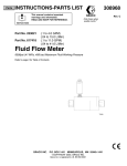
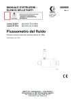
HG6000 Meter Shown
r_246190_309834_1r
0359
Models
Contents
Models . . . . . . . . . . . . . . . . . . . . . . . . . . . . . . . . . . . 2
Warnings . . . . . . . . . . . . . . . . . . . . . . . . . . . . . . . . . 3
Installation . . . . . . . . . . . . . . . . . . . . . . . . . . . . . . . . 5
Dust and Foreign Matter . . . . . . . . . . . . . . . . . . . 5
Installing the Flow Meter . . . . . . . . . . . . . . . . . . . 5
Grounding . . . . . . . . . . . . . . . . . . . . . . . . . . . . . . 6
Operation . . . . . . . . . . . . . . . . . . . . . . . . . . . . . . . . . 7
Pressure Relief Procedure . . . . . . . . . . . . . . . . . 7
Flow Meter Verification . . . . . . . . . . . . . . . . . . . . 7
Troubleshooting . . . . . . . . . . . . . . . . . . . . . . . . . . . 8
Maintenance . . . . . . . . . . . . . . . . . . . . . . . . . . . . . . . 9
Residue Build-up on the Meter Gears . . . . . . . . . 9
Flushing the Meter . . . . . . . . . . . . . . . . . . . . . . . 9
Disassembly . . . . . . . . . . . . . . . . . . . . . . . . . . . . 9
Assembly . . . . . . . . . . . . . . . . . . . . . . . . . . . . . 10
Parts . . . . . . . . . . . . . . . . . . . . . . . . . . . . . . . . . . . . 11
Model 246190, HG6000 Meter . . . . . . . . . . . . . 11
Model 280560, HG6000 Meter . . . . . . . . . . . . . 12
Part No. 15V820 Helical Gear Fluid Flow Meter
Assembly . . . . . . . . . . . . . . . . . . . . . . . . . . . 13
Model 246340, HG6000HT Meter and
Model 24R174, HG6000HT-FM Meter . . . . 14
Model 246652, HG6000HR Meter and
Model 24P688, HG6000HR-FM Meter . . . . 16
Dimensions . . . . . . . . . . . . . . . . . . . . . . . . . . . . . . . 17
Technical Data . . . . . . . . . . . . . . . . . . . . . . . . . . . . 18
Accessories . . . . . . . . . . . . . . . . . . . . . . . . . . . . . . 19
Graco Standard Warranty . . . . . . . . . . . . . . . . . . . 20
Graco Information . . . . . . . . . . . . . . . . . . . . . . . . . 20
Models
HG6000 Meter, Part No. 246190
HG6000 Meter, Part No. 280560
Standard Resolution
0.013 to 6.0 gpm (50 to 22,712 cc/min) Flow Range
180°F (82°C) Maximum Operating Temperature
Standard Resolution
0.013 to 6.0 gpm (50 to 22,712 cc/min) Flow Range
140°F (60°C) Maximum Operating Temperature
HG6000HR Meter, Part No. 246652
* HG6000 Meter, Part No. 15V820
High Resolution
0.007 to 2.0 gpm (25 to 7571 cc/min) Flow Range
180°F (82°C) Maximum Operating Temperature
Standard Resolution
0.013 to 6.0 gpm (50 to 22,712 cc/min) Flow Range
140°F (60°C) Maximum Operating Temperature
* Uses sensor approved for use on ProMix 2KS Control Platform.
II 1 G
HG6000HR-FM Meter, Part No. 24P688
High Resolution for Filled Materials
0.007 to 2.0 gpm (25 to 7571 cc/min) Flow Range
180°F (82°C) Maximum Operating Temperature
EExia II A T3
FM08ATEX0074
HG6000HT Meter, Part No. 246340
Heated, Standard Resolution
0.013 to 6.0 gpm (50 to 22,712 cc/min) Flow Range
240 VAC, 400 Watts, 1.67 Amps
400°F (204°C) Maximum Operating Temperature
HG6000HT-FM Meter, Part No. 24R174
Heated, Standard Resolution for Filled Materials
0.013 to 6.0 gpm (50 to 22,712 cc/min) Flow Range
240 VAC, 400 Watts, 1.67 Amps
400°F (204°C) Maximum Operating Temperature
2
309834R
Warnings
Warnings
The following warnings are for the setup, use, grounding, maintenance, and repair of this equipment. The exclamation point symbol alerts you to a general warning and the hazard symbols refer to procedure-specific risks. When
these symbols appear in the body of this manual, refer back to these Warnings. Product-specific hazard symbols and
warnings not covered in this section may appear throughout the body of this manual where applicable.
WARNING
EQUIPMENT MISUSE HAZARD
Equipment misuse can cause the equipment to rupture or malfunction and result in serious injury.
• This equipment is for professional use only.
• Use the equipment only for its intended purpose. Call your Graco distributor for information.
• Read all instruction manuals, tags, and labels before operating equipment.
• Check equipment daily. Repair or replace worn or damaged parts immediately.
• Do not alter or modify this equipment. Use only Graco parts and accessories.
• Do not exceed the maximum working pressure of the lowest rated system component.
• Be sure that all spray/dispensing equipment and accessories are rated to withstand the maximum
working pressure of the pump. Do not exceed the maximum working pressure of any component or
accessory used in the system.
• Route hoses and cables away from traffic areas, sharp edges, moving parts, and hot surfaces.
• Do not exceed the maximum temperature rating of any system component.
• Use fluids and solvents that are compatible with equipment wetted parts. See Technical Data in all
equipment manuals. Read fluid and solvent manufacturer’s warnings.
• Always wear protective eyewear, gloves, clothing, and respirator as recommended by the fluid and
solvent manufacturer.
• Comply with all applicable local, state, and national fire, electrical, and safety regulations.
FIRE, EXPLOSION, AND ELECTRIC SHOCK HAZARD
Improper grounding, poor air ventilation, open flames, or sparks can cause a hazardous condition and
result in fire or explosion and serious injury.
• Ground the equipment and the object being dispensed.
• Do not use this equipment with flammable liquids.
• Keep the dispense area free of debris, including solvent, rags, and gasoline.
• If there is any static sparking or you feel an electric shock while using the equipment, stop dispensing immediately. Do not use the equipment until you have identified and corrected the problem.
• Be sure all electrical work is performed by a qualified electrician only.
• Have any checks, installation, or service to electrical equipment performed by a qualified electrician
only.
• Be sure all electrical equipment is installed and operated in compliance with applicable codes
• Be sure power is disconnected when servicing and repairing equipment
• Before operating the equipment, extinguish all open flames or pilot lights in the dispense area
• Do not smoke in the dispensing area.
• Keep liquids away from the electrical components
• Disconnect electrical power at the main switch before servicing the equipment.
309834R
3
Warnings
WARNING
SKIN INJECTION HAZARD
Spray from the gun, leaks, or ruptured components can inject fluid into your body and cause extremely
serious injury, including the need for amputation. Fluid splashed in the eyes or on the skin can also
cause serious injury.
• Fluid injected into the skin might look like just a cut, but it is a serious injury. Get immediate surgical
treatment.
• Do not stop or deflect fluid leaks with you hand, body, glove, or rag.
• Follow the Pressure Relief Procedure in your separate equipment manuals whenever you are
instructed to: relieve pressure; stop dispensing; clean, check, or service the equipment; or install or
clean a nozzle.
• Tighten all the fluid connections before operating the equipment.
• Check the hoses, tubes, and couplings daily. Replace worn, damaged, or loose parts immediately.
Permanently coupled hoses cannot be repaired; replace the entire hose.
• Always wear eye protection and protective clothing when installing, operating, or servicing this dispensing equipment.
• Never wipe off build-up around the nozzle or inlet cap until pressure is fully relieved.
TOXIC FLUID OR FUMES HAZARD
Hazardous fluids or toxic fumes can cause serious injury or death if splashed in the eyes or on the skin,
swallowed, or inhaled.
• Provide fresh air ventilation to avoid the buildup of vapors from the fluid being dispensed.
• Know the specific hazards of the fluid you are using.
• Store hazardous fluid in an approved container. Dispose of hazardous fluid according to all local,
state and national guidelines.
• Always wear protective eyewear, gloves, clothing and respirator as recommended by the fluid and
solvent manufacturer.
• Avoid exposure to heated material fumes.
HOT SURFACE AND FLUID HAZARD
Heated fluid can cause severe burns and can cause equipment surfaces to become very hot.
• Wear protective gloves and clothing when operating this equipment in a heated system.
• Do not touch the metal heat sink when the surface is hot.
• Allow the equipment to cool thoroughly before servicing.
• Some heated systems are designed to dispense Polyurethane (PUR) heated materials. PUR Systems are supplied with ventilation hoods, and require proper ventilation and specifically designed
system components.
4
309834R
Installation
Installation
Installing the Flow Meter
•
Flow volume can only be measured at the location
where the flow meter is installed.
Dust and Foreign Matter
•
Do not use more than 200 ft. (61 m) of cable.
Avoid having dust or foreign matter enter the flow meter
by taking the following precautions:
•
Refer to FIG. 1 to locate and install the flow meter,
connectors, and fluid shutoff valves. Install a check
valve to prevent backflow. The arrows on the flow
meter and check valve show the direction of fluid
flow.
•
Thoroughly flush the fluid supply lines before installing the flow meter.
•
When installing fittings, make sure that no sealing
tape overlaps into the inside of the pipe.
•
The shutoff valves allow you to isolate the meter for
service.
•
Install a 30 mesh fluid filter upstream of the flow
meter.
•
•
The flow meter was calibrated in oil. Flush the meter
with a compatible solvent prior to use.
Refer to the Technical Data and Dimensional
Drawings for dimension, inlet/outlet size, temperature and other specifications.
CAUTION
The use of PTFE tape or pipe seal on fluid fittings
upstream of this meter should be avoided if possible.
Contaminants from sealing material may damage the
meter.
Electronic Sensor Device
Fluid Shutoff Valve
on inlet side
Cable
Flow Meter
Fluid Line
Fluid Shutoff Valve
on outlet side
Fluid Filter
Flow
FIG. 1
309834R
5
Installation
Grounding
2. Never use the flow meter with an electrostatic gun
isolation stand.
Sensor Connector Pin-out
1. Always ground the fluid supply unit, using one of the
following options:
4
a. Mount the meter to a grounded conductive surface, or
b. Connect the conductive fluid hose to the meter
inlet and outlet.
c.
Connect a ground wire to the meter’s M6
mounting holes.
3
1
Pin 1: +10-30 Vdc Supply
Pin 2: Signal Out
Pin 3: Ground
Pin 4: No Connection
2
NOTE: This drawing shows the pin connector used on
meters 246190 Series D, 246340 Series D, 246652
Series C, and newer. Older meters used a 5-pin connector.
Sensor Kit 246786 now includes a cable with a 4-pin
connector, to replace the existing cable connection.
FIG. 2
6
309834R
Operation
Operation
Flow Meter Verification
Pressure Relief Procedure
1. Turn off the fluid supply to the meter.
2. Shut off all electrical power to the fluid system.
3. Follow the Pressure Relief Procedure for your fluid
system dispensing device.
Flow Meter Function
This is a positive displacement, gear flow meter. The
gear flow meter is highly accurate, even with low flow
rates. The fluid flowing through the meter rotates the
gears. The gear position is monitored by a sensor
device. An electrical impulse is produced by the sensor
each time a gear tooth moves past it.
Recommended Usage
The factory calibration factor (k factor) for the flow meter
is stated in the Technical Data section of the manual.
This calibration factor is the number of flow meter pulses
per liter, as determined by a measurement with oil.
Most sealant and adhesive materials are compressible
and, since the flow meter is measuring the material
under high pressure, the actual volume of material may
vary slightly from the measured volume due to this compressibility.
To adjust the flow meter k factor to reflect the uncompressed volume dispensed more accurately, perform the
following steps:
1. Obtain a beaker, 500 cc or larger, and measure the
mass of the empty beaker.
2. Manually dispense material into the beaker.
3. Record both the volume displayed and the current
flow meter k factor (pulses per liter).
4. Measure the mass of the full beaker.
•
•
See the Technical Data for fluid and ambient temperature limits.
Only use the flow meter with fluids that are compatible with the “Wetted Parts” listed in the Technical
Data.
Flow Volume Range
5. Subtract the weight of the empty beaker to determine the fluid mass.
6. Calculate the actual volume dispensed:
fluid mass (g) = volume (cc)
density (g/cc)
7. Calculate the new flow meter k factor:
k factor = displayed volume (cc) X k factor (old)
See Technical Data. on page 18 for flow volume range.
measured volume (cc)
CAUTION
The flow meter gears and bearings can be damaged if
they rotate at too high a speed. To avoid high speed
rotation, open the fluid valve gradually. Do not
over-speed the gear with air or solvent. To prolong
meter life, do not use the meter above its maximum
flow rate.
309834R
8. Repeat steps 1-7 to validate the k factor.
7
Troubleshooting
Troubleshooting
The sensor is not a serviceable part. Replace it if
it is malfunctioning.
Problem
Cause
No flow volume displayed at monitor- Flow volume is too low to measure
ing unit
Fluid is not flowing
Fluid is not flowing
Damaged cable
Improper input voltage to sensor
Damaged sensor
Clogs in fluid line or in meter
Gears worn or damaged
8
Solution
Increase flow volume.
See Problem: Fluid is not flowing,
below.
Replace cable.
Make sure input power is 10-30 Vdc.
Replace sensor if it is malfunctioning.
Clean fluid line and/or meter; see
Maintenance section.
Service meter; see Maintenance
section.
309834R
Maintenance
Maintenance
4. Follow the Pressure Relief Procedure, then disconnect the fluid line from the solvent supply unit.
5. Reconnect the fluid line to the fluid supply.
CAUTION
Do not immerse the meter in solvent with the electronic
sensor installed. Solvent could damage the electrical
components.
Air purge is not recommended for any gear-type flow
meter. Air purges do not provide the lubrication the
meter gears require.
Residue Build-up on the Meter
Gears
Residue build-up may cause the meter gears to bind or
stop rotating, which decreases the meter accuracy and
makes meter recalibration necessary. As more build-up
occurs, recalibration is required more often.
The frequency that your meter requires cleaning
depends on the type of fluid being used. Excessive residue build-up usually means that you are using improper
cleaning solvents and/or cleaning sequences or processes.
•
Check the meter routinely to develop the correct
cleaning schedule.
•
Use the proper cleaning solvent for the fluid being
metered.
Flushing the Meter
Flush the fluid supply line and meter fluid reservoir daily
with a compatible solvent as instructed below.
1. Follow the Pressure Relief Procedure, on page 7.
2. Connect the fluid line to the solvent supply unit.
3. Flush the meter until it is clean.
309834R
6. Turn on the fluid supply.
7. Operate until the meter and fluid line are free of solvent.
CAUTION
It is not recommended that the meter be operated or
flushed with water. Should this occur, residual water
should be removed with alcohol and the internal components of the meter should be coated with a light film
of oil. If the device is to remain inoperative for an
extended period of time, internal components of the
meter should be coated with a light film of oil.
Disassembly
Clean and service the meter at a clean
work-bench. Use only lint-free cloth on parts.
1. Follow the Pressure Relief Procedure, on page 7.
Then close the fluid shut-off valve on each side of
the meter.
2. Disassemble the sensor assembly (19) and sensor
pad (17) from the flow meter housing by removing
M4 screws (18 & 20). See page 11.
3. Loosen the six M8 screws (2) from the end housing
(1) of the flow meter.
4. Remove four of the six screws (2) from the end
housing (1) keeping the two opposite bolts engaged
by several threads.
CAUTION
To avoid damaging the shafts (4 & 8), keep the housings parallel to each other when separating them; do
not rock the housings from side to side. Do not use
chisels or screwdrivers to split and pry apart the housings.
9
Maintenance
5. Hold the end housing (1) and gently alternately tap
on the two screws (2) with a hammer to separate
the middle housing (11).
7. Insert the 3-tooth helical gear (8) into the gear bearing (5), making sure the two helical gears mesh with
each other.
6. Remove the last two screws (2) and carefully separate the end (1) and middle housings (11) completely.
8. Line up the holes in the middle housing (11) with the
helical gears, and carefully slide the housing over
the gears.
7. Remove and inspect the helical gear assemblies (4
& 8), gear bearings (5 & 7), and gear spacer (9) by
lifting the gears straight out.
Use locating dowel pins (13). Choose dowel length
based on the depth of the dowel holes in the
housings. If both housings have 0.19 in. deep dowel
holes, use 0.312 in. dowels. If one housing has 0.19
in. deep dowel holes and the other housing has 0.4
in. deep dowel holes, use 0.55 in. dowels. If both
housings have 0.4 in. deep dowel holes, use.75 in.
dowels.
8. Check that the ball bearings (6) and dowel pins (13)
did not fall out of their locations.
9. Unscrew the six M8 screws (15) and remove the
end cap (14).
Inspection
1. Inspect the gears, shafts and bearings.
2. Inspect the housings.
3. Check the o-ring (12) condition, replace the o-ring if
necessary.
4. Clean the meter parts with compatible solvent.
Assembly
1. With the middle housing (11) inlet side pointing up,
check that the o-ring (12) is seated snugly on the
end cap (14). Screw the end cap (14) to the middle
housing (11) using M8 screws (15) and hand
tighten. Make sure the four index holes on the housing line up. Torque the six screws (15) to 350 +/- 15
in-lb. (39.5 +/- 1.7 N•m). Do not overtighten.
9. Insert the two opposing screws (2) in the end housing (1) and alternately tighten each down until the
two housing parts (1 and 11) are together.
10. Insert and tighten the remaining four screws (2) in
the end housing (1).
11. Torque the six screws (2) in the end housing (1) to
350 +/- in-lb (39.5 +/- 1.7 N•m). Do not overtighten.Assemble the sensor assembly (19) and
sensor pad (17) to the flow meter using M4 screws
(18 & 20). Tighten the M4 screws (18 & 20) to 42 +/15 in-lb (4.75 +/- 1.7 N•m). Do not overtighten.
2. Flip the middle housing (11) and end cap (14), so
the outlet side is facing up. Check that o-ring (12) is
seated snugly in its groove.
3. With the end housing (1) facing up, insert the
2-tooth helical gear assembly (4) including the centering spacer bearing into the larger bore of the end
housing (1) with the spur gear end going first.
4. Slide the shaft spacer (9) over the 2-tooth helical
gear (4) and place it into the large bore of the end
housing (1) above the centering spacer bearing.
5. Press the shaft spacer (9) down until it sits flush in
the end housing (1).
6. Install the gear bearing (5) into its hole in the end
cap (1), lifting the 2-tooth helical gear (4) if necessary.
10
309834R
Parts
Parts
Model 246190, HG6000 Meter
19
23
18
2
17
15
5
3 6
21
13
7a
7e
7b
24
2
7d
7f
7c
22
16
7
1
20
17
9
5 15
6 3
7e
7e
16
8
r_246190_309834_3r
5
4
3
6 3
1
2 1
Ref.
1
2
3
4†
5†
6†
7*
7a
7b
7c
7d
7e
7f
8*
Part
117535
246594
101680
234052
234053
13*
15†
309834R
Description
HOUSING, end
SCREW, cap, socket head
GUIDE, gear
INSERT, bearing
BEARING, gear (includes 4)
BALL, bearing
GEAR, sub-assembly; 2-tooth
(includes 7a-7f)
GEAR
ROD, gear
GEAR, spur
GUIDE, rod
ROD, gear
BEARING
GEAR, sub-assembly; 3-tooth
(includes 7e)
SPACER, shaft, gear
INSERT, bearing
Qty.
1
6
1
1
3
3
1
1
1
1
1
3
1
1
1
2
1
Torque to 350 +/- 15 in-lb (39.5 +/- 1.7 N•m)
2
Torque to 42 +/- 15 in-lb (4.75 +/- 1.7 N•m)
3
After ball (6) is placed into bearings,
apply grease (31) into bearing area.
Ref.
16*†
17†
18†
19
20
21
Part
Description
117541 SEAL
PIN, dowel, 0.75 in.
HOUSING, middle
CAP, end
117536 SCREW, cap, socket head
24U114 SENSOR, Model 246190 only
239717 SENSOR, Model 280560 only
22
15B413 PAD, sensor
23
114100 SCREW, cap, socket head
24
106371 SCREW, mach, hex flat head
31†
LUBRICANT, grease
★
*
Qty.
2
2
1
1
6
1
1
1
2
2
1
Included in Gear Replacement Kit 246596.
† Included in Bearing Replacement Kit 253215.
★ Not shown.
11
Parts
Model 280560, HG6000 Meter
19
23
18
2
17
15
5
3 6
21
13
7a
2
7e
7b
24
7d
7f
7c
22
16
7
20
1
17
9
5 15
6 3
7e
7e
8
16
r_246190_309834_3r
5
4
3
6 3
1
2 1
Ref.
1
2
3
4†
5†
6†
7*
7a
7b
7c
7d
7e
7f
8*
13*
15†
12
Part
117535
246594
101680
234052
234053
Description
HOUSING, end
SCREW, cap, socket head
GUIDE, gear
INSERT, bearing
BEARING, gear (includes 4)
BALL, bearing
GEAR, sub-assembly; 2-tooth
(includes 7a-7f)
GEAR
ROD, gear
GEAR, spur
GUIDE, rod
ROD, gear
BEARING
GEAR, sub-assembly; 3-tooth
(includes 7e)
SPACER, shaft, gear
INSERT, bearing
Qty.
1
6
1
1
3
3
1
1
1
1
1
3
1
1
Ref.
16*†
17†
18†
19
20
21
22
23
24
31†
★
*
1
Torque to 350 +/- 15 in-lb (39.5 +/- 1.7 N•m)
2
Torque to 42 +/- 15 in-lb (4.75 +/- 1.7 N•m)
3
After ball (6) is placed into bearings,
apply grease (31) into bearing area.
Part
Description
117541 SEAL
PIN, dowel, 0.75 in.
HOUSING, middle
CAP, end
117536 SCREW, cap, socket head
239717 SENSOR
15B413 PAD, sensor
114100 SCREW, cap, socket head
106371 SCREW, mach, hex flat head
LUBRICANT, grease
Qty.
2
2
1
1
6
1
1
2
2
1
Included in Gear Replacement Kit 246596.
† Included in Bearing Replacement Kit 253215.
★ Not shown.
1
2
309834R
Parts
Part No. 15V820 Helical Gear Fluid Flow Meter Assembly
(uses sensor approved for use on ProMix 2KS Control Platform)
110
101
102
105
103
102
104
106
109
107
107
TI17224a
108
Ref. Part
Description
Qty.
1
101 280560 METER, HG6000; see page 12
2
102 15M861 REDUCER, pipe; 3/4 npt(m) x 1/4
npt(f)
1
103 166846 ADAPTER; 1/4 npt x 1/4 npsm
1
104 205099 HOSE, fluid, high pressure; ptfe;
2.5 ft (0.76 m); 1/4 npsm(fbe)
1
105 501867 VALVE, check; 1/4 npt(mbe)
309834R
Ref. Part
106 117670
107 115226
108 107530
109
110
Description
Qty.
1
BRACKET, mounting
6
WASHER, lock; M6
2
SCREW, cap, socket head; M6 x
12 mm
4
108328 SCREW, cap, socket head; M6 x
20 mm
1
241799 CABLE, meter; 5 ft (1.52 m)
13
Parts
Model 246340, HG6000HT Meter and
Model 24R174, HG6000HT-FM Meter
29
28
35
27
39
18
2
17
40
4 6
7a
33
15
36
26
13
25
7b
2
41
7d 7f
7c
42
22
33
16
5
7a
7e
32 34
20 3
8
24
7e
31
6
5 4
3
4
30
1
23 3
2 1
1
20 3
Torque to 350 +/- 15 in-lb (39.5 +/-1.7 N•m)
2
Torque to 45 +/- 15 in-lb (5.09 +/- 1.7 N•m)
3
Apply thermal lubricant (45)
4
After ball (6) is placed into bearings,
apply grease (52) into bearing area.
16
r_246340_309834_1p
37 1
19
SCHEMATIC DIAGRAM
WIRING DIAGRAM
20
1
2
HEATERS
TOTAL 400W @240 VOLTS
HEATERS
3
6 7
5 1 2
4
3
20
21
SENSOR RTD
23
26
25
SENSOR
4
5 (NOT USED)
6 (NOT USED)
7 (NOT USED)
38
NOTE: This flow meter is controlled by the system controls.
14
309834R
Parts
Model 246340, HG6000HT Meter and
Model 24R174, HG6000HT-FM Meter
Ref.
1
2
3
4†
5†
6†
7*
7**
Part
117535
246594
101680
234052
24R205
7a
7b
7c
7d
7e
7f
8*
234053
8**
24R690
13*
15†
16*†
17†
18†
19
20
21
22
116614
15B774
15C336
23
24
25
26
27
28
29
C32255
C34043
101674
112144
C34040
189930
290228
117541
309834R
Description
Qty.
1
HOUSING, end
6
SCREW, cap, socket head
1
GUIDE, gear
1
INSERT, bearing
3
BEARING, gear (includes 4)
3
BALL, bearing
1
GEAR, sub-assembly; 2-tooth
(includes 7a-7f); Model 246340
only
GEAR, sub-assembly; 2-tooth,
(includes 7a-7f); Model
24R174 only
1
GEAR
1
ROD, gear
1
GEAR, spur
1
GUIDE, rod
3
ROD, gear
1
BEARING
1
GEAR, sub-assembly; 3-tooth
(includes 7e); Model 246340
only
1
GEAR, sub-assembly; 3-tooth
(includes 7e); Model 24P690
only
1
SPACER, shaft
2
INSERT, bearing
2
SEAL
2
PIN, dowel; 0.75 in.
1
HOUSING, middle
1
CAP, end
2
HEATER, cartridge; 240V
1
INSERT, threaded; m6 x 0.75
1
BRACKET, mounting, electric
connector
1
SENSOR, temperature
1
BRACKET
1
TERMINAL
1
SCREW, mach, pan head
1
COVER
1
LABEL, caution
1
LABEL, caution
Ref.
30
31
32
33
Part
15B773
102235
115862
115861
34
35
36
37
38
115860
C19269
100171
117536
065345
39
40
114100
24U114
41
42
45★
50★
52†
★
106371
15C506
*
Description
Qty.
2
INSERT, threaded; m8
2
SCREW, cap, hex head
5
CONNECTOR, male, crimp
1
BULKHEAD, housing, insulating
1
INSERT, male
2
SCREW, mach, slotted head
2
SCREW, mach, pan head
6
SCREW, cap, socket head
WIRE, copper, electrical;
16AWG, 0.5
2
SCREW, cap, socket head
1
SENSOR, heli gear, hi resolution
2
SCREW, mach, hex flat head
1
PAD, sensor
1
LUBRICANT, thermal
1
TUBE, polyolefin, shrinkable
1
LUBRICANT, grease
Included in HG6000HT Gear Replacement Kit
246596.
** Included in HG6000HT-FM Gear Replacement Kit
16U675.
† Included in Bearing Replacement Kit 253215.
★ Not shown.
15
Parts
Model 246652, HG6000HR Meter and
Model 24P688, HG6000HR-FM Meter
19
23
18
2
17
3 6
21
13
7a
2
7e
7b
24
15
5
7d
16
7f
22
7c
7
20
1
9
5
15
16
17
7e
7e
6 3
8
r_246652_309834_1l
5
4
3
6 3
1
2
Ref.
1
2
3
4†
5†
6†
7*
7**
Part
117535
246594
101680
246686
24P689
7a
7b
7c
7d
7e
7f
8*
234053
8**
24P690
16
1
Torque to 350 +/- 15 in-lb (39.5 +/- 1.7 N•m)
2
Torque to 42 +/- 15 in-lb (4.75 +/- 1.7 N•m)
3
After ball (6) is placed into bearings,
apply grease (31) into bearing area.
1
Description
Qty.
1
HOUSING, end
6
SCREW, cap, socket head
1
GUIDE, gear
1
INSERT, bearing
3
BEARING, gear (includes 4)
3
BALL, bearing
1
GEAR, sub-assembly; 2-tooth
(includes 7a-7f); Model 246652
only
1
GEAR, sub-assembly; 2-tooth
(includes 7a-7f); Model 24P688
only
1
GEAR
1
ROD, gear
1
GUIDE, rod
3
ROD, gear
1
BEARING
1
GEAR, spur, 22 teeth
1
GEAR; sub-assembly; 3-tooth
(includes 7d); Model 246652
only
1
GEAR; sub-assembly; 3-tooth
(includes 7d); Model 24P688
only
Ref.
13*
15†
16*†
17†
18†
19
20
21
22
23
24
31†
★
*
Part
117541
117536
24U114
15B413
114100
106371
Description
SPACER, shaft
INSERT, bearing
SEAL
PIN, dowel; 0.75 in.
HOUSING, middle
CAP, end
SCREW, cap, socket head
SENSOR
PAD, sensor
SCREW, cap, socket head
SCREW, mach, hex flat head
LUBRICANT, grease
Qty.
1
2
2
2
1
1
6
1
1
2
2
1
Included in HG6000HR Gear Replacement Kit
246949.
** Included in HG6000HR-FM Gear Replacement Kit
16U006.
† Included in Bearing Replacement Kit 253215.
★ Not shown.
309834R
Dimensions
Dimensions
Flow Meter Port Size
3.0 in.
76.2 mm
5.6 in.
142.2 mm
6.1 in.
154.9 mm
3/4 - 14 npt(f) Outlet
3/4 - 14 npt(f) Inlet
Flow Meter Mounting Holes
2.1 in.
(TOP VIEW)
(53.3 mm)
Flow Meter Mounting Holes
(BOTTOM VIEW)
1.0 in.
(25.4 mm)
TI9122A
Weight 12 lbs (5.44 kg)
M6 x 1
309834R
M4 x 7 x .320
r_246190_309834_2r
17
Technical Data
Technical Data
Category
Data
Maximum Working Fluid Pressure 6000 psi (41 MPa, 410 bar)
Flow Range
Models 246190, 246340, 280560, 15V820, and 24R174: 0.013 to 6.0 gpm (50
to 22,712 cc/min)
Models 246652 and 24P688: 0.007 to 2.0 gpm (25 to 7571 cc/min.)
Maximum Operating
Temperature
Models 246190, 246652, and 24P688: 180° F (82° C)
Models 280560 and 15V820: 140° F (60° C)
Models 246340 and 24R174: 400° F (204° C)
Maximum Ambient
Temperature
Models 246190, 246652, 246340, 24P688, and 24R174: 180° F (80° C)
Models 280560 and 15V820: 140° F (60° C)
Fluid Viscosity Range
30 - 1,000,000 cps
Maximum Cable Length
200 ft (61 m)
Flow Meter Inlet/Outlet
3/4 npt(f)
Resolution (K-Factor)
Models 246190, 246340, 280560, 15V820, and 24R174 - (0.286 cc/pulse)
(3500 pulses/liter)
Models 246652 and 24P688 - (0.143 cc/pulse) (7000 pulses/liter)
Accuracy
+/- 0.25%*
Repeatability
+/- 0.1%
Supply Voltage
10 - 30 Vdc
Typical Current
15 mA
Approvals
CE: Models 246190, 246652, 246340, 280560, 24P688, and 24R174
EX: Model 15V820 only.
Wetted Parts
303 Stainless Steel, 440 SST, Carpenter Technology 7-mo Plus® Duplex SST,
Tungsten Carbide, PTFE
* For most commonly used coatings, the flow meter reading will be accurate to within +/- 0.25%. Accuracy will diminish
at low viscosities and low flow rates.
18
309834R
Accessories
Pressure Drop vs. Flow Rate in 1000 cps Oil
80
Pressure Drop (PSI)
70
60
50
40
30
20
10
0
0.00
0.25
0.50
0.75
1.00
1.25
1.50
1.75
2.00
Flow Rate (GPM)
Accessories
Use Only Genuine Graco Parts and Accessories
Fluid Filter C58997 (30 mesh)
5000 psi (350 bar) Maximum Working Pressure
High Resolution Meter Sensor
Replacement Kit 246786
Recommended for use with Fluid Filter C58997.
The sensor update has been made to meters 246190
Series D, 246340 Series D, 246652 Series C, and
newer. Cable 123409 is added to this kit (Series B) to
replace the existing sensor cable used on older series
meters than those listed above.
Filter Bank C59547
Electrical Cable 123409
5000 psi (350 bar) Maximum Working Pressure
For connecting to sensor (included in Sensor Replacement Kit 246786, Series B).
With stainless steel bowl and polyethylene support
30 Mesh Filter Screen 515222
C58997 Filter with Mounting Bracket, Shutoff Valves,
and 30 Mesh Filter Screen
Fluid Shutoff Valve 521477
20 in. (.51 m) cable with one end terminated for connection to the sensor and the other end is left bare for connection to a junction box or special connector.
5000 psi (350 bar) Maximum Working Pressure
1 in. npt(f). For shutting off the fluid and isolating the
flow meter for service or replacement. See page 5.
309834R
19
Graco Standard Warranty
Graco warrants all equipment referenced in this document which is manufactured by Graco and bearing its name to be free from defects in material and
workmanship on the date of sale to the original purchaser for use. With the exception of any special, extended, or limited warranty published by Graco, Graco
will, for a period of twelve months from the date of sale, repair or replace any part of the equipment determined by Graco to be defective. This warranty applies
only when the equipment is installed, operated and maintained in accordance with Graco’s written recommendations.
This warranty does not cover, and Graco shall not be liable for general wear and tear, or any malfunction, damage or wear caused by faulty installation,
misapplication, abrasion, corrosion, inadequate or improper maintenance, negligence, accident, tampering, or substitution of non-Graco component parts.
Nor shall Graco be liable for malfunction, damage or wear caused by the incompatibility of Graco equipment with structures, accessories, equipment or
materials not supplied by Graco, or the improper design, manufacture, installation, operation or maintenance of structures, accessories, equipment or
materials not supplied by Graco.
This warranty is conditioned upon the prepaid return of the equipment claimed to be defective to an authorized Graco distributor for verification of the claimed
defect. If the claimed defect is verified, Graco will repair or replace free of charge any defective parts. The equipment will be returned to the original purchaser
transportation prepaid. If inspection of the equipment does not disclose any defect in material or workmanship, repairs will be made at a reasonable charge,
which charges may include the costs of parts, labor, and transportation.
THIS WARRANTY IS EXCLUSIVE, AND IS IN LIEU OF ANY OTHER WARRANTIES, EXPRESS OR IMPLIED, INCLUDING BUT NOT LIMITED TO
WARRANTY OF MERCHANTABILITY OR WARRANTY OF FITNESS FOR A PARTICULAR PURPOSE.
Graco’s sole obligation and buyer’s sole remedy for any breach of warranty shall be as set forth above. The buyer agrees that no other remedy (including, but
not limited to, incidental or consequential damages for lost profits, lost sales, injury to person or property, or any other incidental or consequential loss) shall
be available. Any action for breach of warranty must be brought within two (2) years of the date of sale.
GRACO MAKES NO WARRANTY, AND DISCLAIMS ALL IMPLIED WARRANTIES OF MERCHANTABILITY AND FITNESS FOR A PARTICULAR
PURPOSE, IN CONNECTION WITH ACCESSORIES, EQUIPMENT, MATERIALS OR COMPONENTS SOLD BUT NOT MANUFACTURED BY GRACO.
These items sold, but not manufactured by Graco (such as electric motors, switches, hose, etc.), are subject to the warranty, if any, of their manufacturer.
Graco will provide purchaser with reasonable assistance in making any claim for breach of these warranties.
In no event will Graco be liable for indirect, incidental, special or consequential damages resulting from Graco supplying equipment hereunder, or the
furnishing, performance, or use of any products or other goods sold hereto, whether due to a breach of contract, breach of warranty, the negligence of Graco,
or otherwise.
FOR GRACO CANADA CUSTOMERS
The Parties acknowledge that they have required that the present document, as well as all documents, notices and legal proceedings entered into, given or
instituted pursuant hereto or relating directly or indirectly hereto, be drawn up in English. Les parties reconnaissent avoir convenu que la rédaction du
présente document sera en Anglais, ainsi que tous documents, avis et procédures judiciaires exécutés, donnés ou intentés, à la suite de ou en rapport,
directement ou indirectement, avec les procédures concernées.
Graco Information
For the latest information about Graco products, visit www.graco.com.
TO PLACE AN ORDER, contact your Graco distributor or call to identify the nearest distributor.
Phone: 612-623-6921 or Toll Free: 1-800-328-0211 Fax: 612-378-3505
All written and visual data contained in this document reflects the latest product information available at the time of publication.
Graco reserves the right to make changes at any time without notice.
For patent information, see www.graco.com/patents.
2ULJLQDOLQVWUXFWLRQV This manual contains English. MM 309834
Graco Headquarters: Minneapolis
International Offices: Belgium, China, Japan, Korea
GRACO INC. AND SUBSIDIARIES • P.O. BOX 1441 • MINNEAPOLIS MN 55440-1441 • USA
Copyright 2002, Graco Inc. All Graco manufacturing locations are registered to ISO 9001.
www.graco.com
Revised August 2013