1
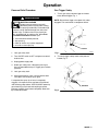
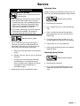
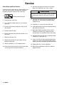
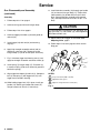
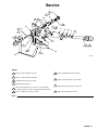
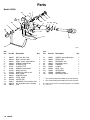
Instructions–Parts List
Inline HDt Texture Gun
309495F
EN
Waterbase Compatible
280 bar (28 MPa, 4000 psi) Maximum Working Pressure
Model 245820, Series C
Ball end valve needle – abrasive material compatible
U.S. Patent No. Des. 342,654
ti13864
Important Safety Instructions
Read all warnings and instructions in this manual.
Save these instructions.
Table of Contents
Warning . . . . . . . . . . . . . . . . . . . . . . . . . . . . . . . . . 2
Operation . . . . . . . . . . . . . . . . . . . . . . . . . . . . . . . 3
Service . . . . . . . . . . . . . . . . . . . . . . . . . . . . . . . . . 5
Parts . . . . . . . . . . . . . . . . . . . . . . . . . . . . . . . . . . 10
Technical Data . . . . . . . . . . . . . . . . . . . . . . . . . . 11
Graco Warranty . . . . . . . . . . . . . . . . . . . . . . . . 12
Graco Phone Number . . . . . . . . . . . . . . . . . . . . 12
WARNING
Fire and explosion hazard: Solvent and paint fumes can ignite or
explode.
To help prevent a fire and explosion:
DUse only in an extremely well ventilated area.
DEliminate all ignition sources; such as pilot lights, cigarettes and
plastic drop cloths (static arc hazard). Do not plug or unplug power
cords or turn lights on or off in spray area.
DGround Sprayer, object being sprayed, paint and solvent pails.
DHold gun firmly to side of grounded pail when triggering into pail.
DUse only conductive airless paint hose.
DDo not use 1,1,1-trichloroethane, methylene chloride, other
halogenated hydrocarbon solvents or fluids containing such
solvents in pressurized aluminum equipment. Such use could
result in a chemical reaction, with the possibility of explosion.
DDo not fill fuel tank while engine is running or hot.
DDo not flush with gasoline.
ADVERTÊNCIA
Perigo de incêndio e explosão: os solventes e os vapores da pintura
poderão explodir ou incendiar.
Para ajudar a evitar incêndio e explosão:
DUtilize unicamente em áreas extremamente bem ventiladas.
DElimine todas as fontes de ignição, tais como luzes piloto, cigarros e
arcos de estática resultantes dos plásticos de proteção. Não ligue nem
desligue os cabos de alimentação ou as luzes numa área de
pulverização.
DPonha em contato com a terra o pulverizador, o objeto a ser pulverizado,
e os baldes de tinta e de solventes.
DSegure a pistola firmemente de encontro ao lado do balde em contato com
a terra, quando estiver descarregando para dentro do mesmo.
DUtilize somente tubos flexíveis condutores para pintura a alta pressão.
DNão utilize 1,1,1-tricloroetano, cloreto de metileno, outros solventes de
hidrocarbonetos halogenados ou líquidos contendo tais solventes em
equipamento de alumínio pressurizado. Tal utilização poderá
resultar numa reação química, com possibilidade de explosão.
DNunca abasteça o depósito de combustível com o motor em funcionamento ou quente.
DNão faça a descarga com gasolina.
Skin injection and high pressure hazard: High pressure spray or
leaks can inject fluid into the body.
Perigo de injeção de líquidos à alta pressão: a pulverização ou
vazamentos à alta pressão podem injetar líquido no corpo.
To help prevent injection, always:
DEngage trigger safety latch when not spraying.
DKeep clear of nozzle and leaks.
DNever spray without a tip guard.
DDo PRESSURE RELIEF if you stop spraying or begin servicing
sprayer.
DDo not use components rated less than sprayer Maximum
Working Pressure.
DNever allow children to use this unit.
Para ajudar a evitar injeção de líquido, faça sempre o seguinte:
DEngate o trinco de segurança do gatilho quando não estiver pulverizando.
DMantenha-se afastado dos bocais e locais onde há vazamentos.
DNunca pulverize sem que haja uma proteção na extremidade.
DALIVIE A PRESSÃO quando parar de pulverizar e antes de iniciar a
manutenção do pulverizador.
DNão utilize componentes com uma classificação inferior à do
pulverizador Pressão Máxima de Trabalho.
DNunca permita que crianças utilizem esta unidade.
If high pressure fluid pierces your skin, the injury might look like
“just a cut”. But it is a serious wound! Get immediate surgical treatment.
MISE EN GARDE
Se o líquido a alta pressão penetrar na sua pele, o ferimento poderá
parecer “simplesmente um corte”. Mas é um ferimento grave! Faça
tratamento cirúrgico imediatamente.
ADVERTENCIA
Danger d’incendie et d’explosion : les gaz de solvant et de peinture
peuvent s’enflammer ou exploser.
Pour éviter les risques d’incendie et d’explosion :
Peligro de incendio o explosión: Los gases de los disolventes y de la
pintura pueden inflamarse o provocar una explosión.
Para prevenir incendios y explosiones:
DN’utiliser l’appareil que dans une zone extrêmement bien aérée.
DÉliminer toute source d’inflammation ; telle que veilleuses, cigarettes et
arcs d’électricité statique créés par les toiles de peintre en plastique.
Ne pas brancher et débrancher de cordons électriques, ou allumer et
éteindre des lumières dans la zone de pulvérisation.
DMettre à la terre le pulvérisateur, l’objet à pulvériser ainsi que les seaux
de peinture et de solvants.
DTenir le pistolet fermement contre la paroi d’un seau mis à la terre
lorsqu’on pulvérise dans le seau.
DN’utiliser qu’un flexible pour peinture pulvérisée sans air.
DNe jamais utiliser de trichloroéthane 1,1,1, de chlorure de méthylène,
d’autres solvants à base d’hydrocarbures halogénés, ni de produits
contenant de tels solvants dans un équipement sous pression en
aluminium. Cela pourrait provoquer une réaction chimique avec risque
d’explosion.
DNe jamais remplir le réservoir d’essence lorsque le moteur est chaud
ou en marche.
DNe pas rincer avec de l’essence.
DUse únicamente en un área muy bien ventilada.
DSuprima todas las fuentes de ignición; como luces piloto, cigarrillos y
arcos estáticos de carpetas plásticas para protección contra pintura. No
enchufe ni desenchufe cables de alimentación ni apague ni encienda las
luces en un área de pulverización.
DPonga a tierra el pulverizador, el objeto que recibe el chorro pulverizado,
las cubetas de pintura y disolvente.
DSostenga firmemente la pistola a un lado de la cubeta puesta a tierra cuando
dispare dentro de ella.
DUse solamente mangueras para pintura conductora sin aire.
DNo utilice nunca tricloretano-1,1,1, cloruro de metileno ni otros
disolventes a base de hidrocarburos halógenos o fluidos que contengan
dichos disolventes en un equipo a presión de aluminio. El uso de estas
sustancias puede provocar una intensa reacción química, con riesgos
de explosión.
DNunca llene el estanque de combustible mientras el motor esté en marcha o caliente.
DNo lave con gasolina.
Dangers d’injection cutanée et haute pression : la pulvérisation sous
haute pression ou les fuites peuvent injecter des fluides dans le corps.
Pour éviter les risques d’injection, toujours :
DBloquer le loquet de sécurité de la gâchette à la fin de la pulvérisation.
DSe tenir loin de la buse et des fuites.
DNe jamais pulvériser sans anti-gouttes.
DDÉCHARGER LA PRESSION à la fin de la pulvérisation ou avant de
réparer le pulvérisateur.
DNe pas utiliser de composants dont la pression nominale est inférieure
à la pression maximale de service du système.
DNe jamais permettre aux enfants d’utiliser cet appareil.
Si un fluide haute pression perce la peau, la blessure peut paraître
une “simple coupure” Mais il s’agit bien d’une lésion grave! Consulter
immédiatement un médecin en vue d’une intervention chirurgicale.
Peligro de inyección a través de la pie y alta presión: por la pulverización o las filtraciones a alta presión se pueden inyectar fluidos en el
organismo.
2 309495
Para prevenir la inyección en la piel, siempre:
DEnganche el seguro del gatillo cuando no use el pulverizador.
DNo se acerque a la boquilla ni a las filtraciones.
DNunca aplique fluido pulverizado sin un guardaboquilla.
DRealice el ALIVIO DE PRESIÓN si deja de pulverizar fluido o repara el
pulverizador.
DNo use componentes de capacidad nominal inferior a la presión
máxima de operación del pulverizador.
DNo permita que niños usen esta unidad.
Si fluido de alta presión le penetra la piel, la lesión podría parecer
“sólo un corte”. ¡Es una lesión seria! Consulte de inmediato al médico.
Operation
Pressure Relief Procedure
WARNING
INJECTION HAZARD
System pressure must be manually
relieved to prevent system from starting
or spraying accidentally. Fluid under high
pressure can be injected through skin and cause
serious injury. To reduce risk of injury from injection, splashing fluid, or moving parts, follow Pressure Relief Procedure whenever you:
D
D
D
D
Gun Trigger Safety
1. To lock gun safety, release trigger and rotate
safety toward trigger, Fig. 1.
NOTE: Do not force trigger valve open with safety
engaged. This could result in component failure.
are instructed to relieve pressure,
stop spraying,
check or service any system equipment,
or install or clean spray tip.
Locked
1. Lock gun safety latch.
2. Turn ON/OFF switch to OFF and pressure control
knob to zero.
ti13865a
Fig. 1
2. To unlock trigger safety, rotate safety toward
handle, Fig. 2.
3. Unplug power supply cord.
4. Unlock gun safety latch. Hold metal part of gun
firmly to grounded metal pail. Trigger gun to relieve
pressure.
5. Lock gun safety latch.
6. Open pressure drain valve. Leave pressure drain
valve open until ready to spray again.
If suspected that spray tip or hose is completely
clogged, or that pressure has not been fully relieved
after following steps above, VERY SLOWLY loosen tip
guard retaining nut or hose end coupling to relieve
pressure gradually, then loosen completely. Now clear
tip or hose obstruction.
Unlocked
Fig. 2
ti13866a
309495 3
Operation
Spraying
1.
Relieve pressure; page 3.
2. Lock gun trigger safety.
Vent
3. Install tip and guard.
4. Use lowest possible pump pressure to obtain
desired flow rate.
5. Unlock gun trigger safety.
ti13867a
Fig. 3
Flushing Safety
WARNING
6. Squeeze trigger. Fluid flow begins with slightest
pressure on trigger and stops when trigger is
released.
7. Fig. 3. Periodically inspect gun handle vent for fluid
buildup which could indicate an internal leak.
Service fluid tube and o-ring as needed.
4 309495
FIRE AND EXPLOSION HAZARD
To reduce risk of a fire, explosion, or
serious injury,
Use lowest possible fluid pressure and
maintain firm metal-to-metal contact
between gun and grounded metal pail
during flushing.
Service
WARNING
INJECTION HAZARD
To reduce risk of a serious injury, including fluid injection,
D After adjusting or servicing gun, make sure fluid
does not flow when trigger safety is locked. If
fluid does flow, gun is not assembled properly or
trigger safety is damaged. Reassemble gun or
return it to your nearest Graco distributor. Do
not use gun until problem is corrected.
D Fig. 6. When removing gun from hose, hold hex
end of fluid tube assembly (19) securely to
avoid loosening fluid tube from gun body.
1.
Relieve pressure; page 3.
2. Fig. 4. If fluid continues to flow after trigger is
released, gun valve may need adjustment, be
obstructed or damaged, or valve stem (24), seat
(26), or seal (3) may be worn or damaged.
Adjusting Valve
Trigger travel and valve opening is factory set to 1 in.
(25.4 mm). Use following procedure to adjust setting,
1.
Relieve pressure; page 3.
2. Disconnect gun from hose.
3. Fig. 4. Loosen stem nut (1) and spring housing
(28).
4. Insert a 1/8 hex allen wrench through hole in
spring adjustment screw (21) and into spring
housing (28).
5. Turn spring housing (28) and stem nut (1) to
change trigger travel and size of valve opening.
6. Tighten stem nut (1) to set adjustment.
7. Adjust spring adjustment screw (21) to desired
trigger pull force.
a. Adjust valve or spring tension as instructed on
page 5.
Adjusting Spring Tension
b. Replace valve seal, stem, or seat as instructed
on page 6.
1.
c.
To inspect valve for obstruction or damage,
disassemble gun as instructed on page 7.
Clean and inspect parts. Replace any worn or
damaged parts and assemble gun as
instructed on page 7.
3. Follow torque, sealant and lubrication notes.
Relieve pressure; page 3.
2. Disconnect gun from hose.
3. Fig. 4. Turn spring adjustment screw (21) as
needed until spring force is adjusted to close
valve.
309495 5
Service
Valve Stem and Seal Service
If fluid leaks past v-block seal (3), v-block seal or valve
stem (24) may be worn or damaged. Use following
procedure to replace v-block seal or valve stem.
1.
Relieve pressure; page 3.
2. Disconnect gun from hose.
3. Fig. 4. Unscrew spring retainer (21) and remove
spring (4).
11. Lubricate and torque seal retainer (27) into gun
body (17) to 100–125 in-lb (11.3–14.1 NSm).
CAUTION
Installing valve stem (24) without turning it clockwise
could damage v-block seal and result in fluid leakage.
12. Lubricate and install valve stem threads (24) into
gun body (17). Thread stem assembly through
v-block seal (3).
13. Thread nut (1) all way onto valve stem (24).
4. Unscrew spring housing (28) with a 1/8 inch hex
allen wrench.
14. Install adjustment bracket (20) and spring housing
(28) onto valve stem (24).
5. Unscrew valve seat (35).
15. Apply high strength anaerobic sealant (red) to
threads on valve seat (35). Torque valve seat
into gun body (17) to 26–32 ft-lb (35.3–43.4 NSm).
6. Remove adjustment bracket (20) and stem nut (1)
from stem.
7. Remove valve stem (24).
16. Lubricate and install spring (4) and spring retainer
threads (21) in gun body (17).
8. Remove seal retainer (27) and v-block seal (3).
Replace v-block seal.
17. Insert a 1/8 inch hex allen wrench through spring
retainer (21) and into spring housing (28). Adjust
trigger travel and valve opening to desired position.
9. Secure gun body (17) in an assembly fixture.
18. Tighten stem nut (1) to set adjustment.
10. Lubricate and install v-block seal (3) into gun body
(17) with lips of seal facing into housing.
19. Adjust spring adjustment screw (21) to desired
trigger pull force.
6 309495
Service
3 F
A 42
21 E
17
4 F
28 A
F
1
27 E
20
H
24
5
ti13868a
NOTES:
C
N 35
A
Torque to 6–10 in-lb (0.68–1.13 NSm)
C
Torque to 26–32 ft-lb (35.3–43.4 NSm)
E
Apply lithium base grease to threads
F
Apply lithium base grease
H
Torque to 100–125 in-lb (11.3–14.1 NSm)
N
Apply high strength anaerobic sealant (red)
Fig. 4
Gun Disassembly and Assembly
4. Unscrew setscrew (42), then unscrew fluid tube
assembly (19) from gun body (17).
Disassembly
1.
CAUTION
Relieve pressure; page 3.
2. Follow steps 1 to 7 under Valve Stem and Seal
Service.
3. Fig. 6. Remove two retaining rings (8), rod (13)
and trigger (29).
To avoid loosening connections and damaging gun,
grip gun body (17), not handle (14), when removing
fluid tube assembly (19).
5. Remove gun handle screws (9), gun handle (14),
trigger lock (15), ball (2) and spring (7).
6. Remove seal retainer (27), seal (3) and o-rings (5
and 6).
309495 7
Service
Gun Disassembly and Assembly
(continued)
Assembly
1. Follow steps 9 to 11 on page 6.
11. Install fluid tube assembly (19) through gun handle
(14) and screw it into gun body (17). Torque fluid
tube assembly (19) to 200–250 in-lb (22.6–28.2
NSm). Secure fluid tube assembly with setscrew
(42), and torque setscrew to 6–10 in-lb (0.7–1.13
NSm).
2. Lubricate o-ring (6) and install into gun body.
3. Follow steps 12 to 14 on page 6.
4. Lubricate trigger pivot holes (a) bracket guide (b),
and rod (13).
5. Install trigger (29) with rod (13) and retaining
rings (8).
CAUTION
To avoid loosening connections and damaging gun,
grip gun body (17), not handle (14), when tightening
fluid tube assembly (19).
12. Adjust free travel of trigger as instructed under
Adjusting Valve, page 5.
13. Follow steps 15 to 19 on page 6 to finish assembling gun.
6. Apply high strength anaerobic sealant (red) to
threads on valve seat (35). Torque valve seat
into gun body (17) to 26–32 ft-lb (35.3–43.4 NSm).
9 A
M
7. Fig. 5. Lubricate trigger lock housing area (c) and
apply low strength anaerobic sealant to screws (9).
8. Install spring (7) into gun body (17). Place ball (2)
in center of spring. (Use small amount of grease to
hold ball to spring.)
9. Align trigger lock detent (d) with ball (2). Compress
ball (2) and spring (7) with trigger lock (15) until
trigger lock is seated in housing.
10. While holding trigger lock (15) in place, install gun
handle (14). Secure gun handle with screws (9).
Torque screws to 6–10 in-lb (7.9–9.0 NSm).
8 309495
ti2100a
17
F
c
7 2 15
d
F
c
NOTES:
A
Torque to 6–10 in-lb (0.68–1.13 NSm)
F
Apply lithium base grease
M
Apply low strength anaerobic sealant (blue)
Fig. 5
14
Service
E
21
A 28
E
H 27
20
1
4 F
42
35 C
F
24
F
5
A
3 F
M
9
14
44
32
6
O
2
N
17
7
F
15
8
F a
F b
19 G
K
29
F 13
43
ti13869a
NOTES:
A
Torque to 6–10 in-lb (0.68–1.13 NSm)
C
Torque to 26–32 ft-lb (35.3–43.4 NSm)
E
Apply lithium base grease to threads
F
Apply lithium base grease
G
When removing fluid hose, use wrench on end of fluid tube
assembly (19) hex to avoid loosening fluid tube assembly (19)
H
Torque to 100–125 in-lb (11.3–14.1 NSm)
K Torque to 200–250 in-lb (22.6–28.2 NSm)
M Apply low strength anaerobic sealant (blue)
N Apply high strength anaerobic sealant (red)
O Apply anti-seize lubricant to threads
Fig. 6
309495 9
Parts
Model 245820
16
A
27* 1*
4*
42†
21
28
20*
3*
24*
5
14 32† 44†
9
2
13
6†
35
17
7
15
8
29
19
43
ti13869a
Ref.
No.
Part No.
Description
1*
2
3*
4*
5
6†
7
8
9
13
14
15
16
17
19
20*
100975
102233
102921
102924
102982
111457
111902
112410
111904
15Y468
188231
188232
15Y469
15A977
24B570
188246
NUT, hex; No. 5–40
BALL; stainless steel
SEAL, v-block; polyurethane
SPRING, compression
O-RING; PTFE
O-RING; PTFE
SPRING, compression
RING, retaining
SCREW, handle; flat hd
ROD, trigger
HANDLE, plastic
LOCK, trigger
COVER, gun
HOUSING, fluid; stainless steel
KIT, fluid tube swivel assembly
LINK
10 309495
Qty.
1
1
1
1
1
1
1
2
2
1
1
1
1
1
1
1
Ref.
No.
Part No.
Description
21
24*
27*
28
29
32†
35*
42†
43
44†
188247
236234
188271
188275
237604
155332
245655
103187
15A555
15A556
SCREW, spring adjustment
STEM, valve
RETAINER, seal
HOUSING, spring
TRIGGER
O-RING
SEAT, valve
SETSCREW
GUARD, trigger
RETAINER, guard
Qty.
*
Parts included in Repair Kit 245808, purchased separately.
†
Parts included in Repair Kit 24B570, purchased separately.
1
1
1
1
1
1
1
1
1
1
Y Replacement Instruction and Warning labels are available
at no cost.
Technical Data
Maximum Working Pressure . . . . 4000 psi (280 bar)
Outlet Port Size . . . . . . . . . . . . . . . . . . . . . . . . . . 7/8–14
Inlet Port Size . . . . . . . . . . . . . . . . . . . . . . . . . . 1/2 npt(f)
Valve Orifice . . . . . . . . . . . 0.19 in. (4.83 mm) dia. with
0.25 in. (6.35 mm) carbide ball
Height . . . . . . . . . . . . . . . . . . . . . . . 5.60 in. (142.24 mm)
Width . . . . . . . . . . . . . . . . . . . . . . . . 1.20 in. (30.48 mm)
Length . . . . . . . . . . . . . . . . . . . . . 11.40 in. (289.56 mm)
Weight . . . . . . . . . . . . . . . . . . . . . . . . . 33.79 oz. (958 g)
Wetted Parts
Fluid Section . . . . . . . . . . . 17–4 PH Stainless Steel
Fluid Tube . . . . . . . . . . . 300 Series Stainless Steel
Valve Needle . . . . . . . . . . . . . Carbide and 17–4 PH
Stainless Steel
Valve Seat . . . . . . . . . . . . . . . Carbide and 17–4 PH
Stainless Steel
Other . . Stainless Steel, Fluoroelastomer, PTFE,
and Polyurethane
309495 11
Graco Warranty/Garantie Graco
Garantía Graco/Garantia da Graco
Graco warrants all equipment listed in this manual which is manufactured by Graco and bearing its name to be free from defects in
material and workmanship on the date of sale to the original purchaser for use. With the exception of any special extended or limited
warranty published by Graco, Graco will, for a period of twelve months from the date of sale, repair or replace any part of the equipment
determined by Graco to be defective. This warranty applies only when the equipment is installed, operated and maintained in
accordance with Graco’s written recommendations.
This warranty does not cover, and Graco shall not be liable for general wear and tear, or any malfunction, damage or wear caused by
faulty installation, misapplication, abrasion, corrosion, inadequate or improper maintenance, negligence, accident, tampering, or
substitution of non-Graco component parts. Nor shall Graco be liable for malfunction, damage or wear caused by the incompatibility of
Graco equipment with structures, accessories, equipment or materials not supplied by Graco, or the improper design, manufacture,
installation, operation or maintenance or structures, accessories, equipment or materials not supplied by Graco.
This warranty is conditioned upon the prepaid return of the equipment claimed to be defective to an authorized Graco distributor for
verification of the claimed defect. If the claimed defect is verified, Graco will repair or replace free of charge any defective parts. The
equipment will be returned to the original purchaser transportation prepaid. If inspection of the equipment does not disclose any defect
in material or workmanship, repairs will be made at a reasonable charge, which charges may include the costs of parts, labor, and
transportation.
Graco’s sole obligation and buyer’s sole remedy for any breach of warranty shall be as set forth above. The buyer agrees that no other
remedy (including, but not limited to, incidental or consequential damages for lost profits, lost sales, injury to person or property, or any
other incidental or consequential loss) shall be available. Any action for breach of warranty must be brought within two (2) years of the
date of sale.
GRACO MAKES NO WARRANTY, AND DISCLAIMS ALL IMPLIED WARRANTIES OF MERCHANTABILITY AND FITNESS FOR
A PARTICULAR PURPOSE IN CONNECTION WITH ACCESSORIES, EQUIPMENT, MATERIALS OR COMPONENTS SOLD BUT
NOT MANUFACTURED BY GRACO. These items sold, but not manufactured by Graco (such as electric motors, gas engines,
switches, hose, etc.), are subject to the warranty, if any, of their manufacturer. Graco will provide purchaser with reasonable assistance
in making any claim for breach of these warranties.
In no event will Graco be liable for indirect, incidental, special or consequential damages resulting from Graco supplying equipment
hereunder, or the furnishing, performance, or use of any products or other goods sold hereto, whether due to a breach of contract,
breach of warranty, the negligence of Graco, or otherwise.
FOR GRACO CUSTOMERS SPEAKING FRENCH, SPANISH AND PORTUGUESE
The parties acknowledge that they have required that the present document, as well as all documents, notices and legal proceedings
entered into, given or instituted pursuant hereto or relating directly or indirectly hereto, be drawn up in English.
POUR LES CLIENTS DE GRACO PARLANT FRANÇAIS
Les parties reconnaissent avoir convenu que la rédaction du présent document, ainsi que tous les documents, avis et procédures
judiciaires exécutés, donnés ou intentés à la suite de ou en rapport, directement ou indirectement, avec les procédures concernées,
sera en anglais.
PARA CLIENTES DE GRACO DE HABLA ESPAÑOLES
Las partes reconocen que han requerido que el presente documento, al iqual que todos los documentos, notificaciones y
procedimientos legales en que se incurra conforme a esta infomación o en relación indirecta o directa con la misma, sea redactado en
inglés.
PARA CLIENTES DE LÍNGUA PORTUGUESA DA GRACO
As partes confirmam que solicitaram que o presente documento, assim como todos os demais documentos, notas e processos legais
inseridos, atribuídos ou instituídos de acordo com o mesmo ou relacionados direta ou indiretamente a este documento, fossem
redigidos em inglês.
ADDITIONAL WARRANTY COVERAGE
Graco does provide extended warranty and wear warranty for products described in the “Graco Contractor Equipment Warranty
Program”.
Graco Phone Number
For the latest information about Graco products, visit www.graco.com.
TO PLACE AN ORDER, contact your Graco distributor, or call 1–800–690–2894 Toll Free, to identify the distributor closest to you.
All written and visual data contained in this document reflects the latest product information available at the time of publication. Graco reserves the
right to make changes at any time without notice.
For patent information, see www.graco.com/patents.
Original instructions. This manual contains English. MM 309495
Graco Headquarters: Minneapolis
International Offices: Belgium, China, Japan, Korea
GRACO INC. AND SUBSIDIARIES S P.O. BOX 1441 S MINNEAPOLIS MN 55440–1441 S USA
Copyright 2002, Graco Inc. All Graco manufacturing locations are registered to ISO 9001.
www.graco.com
Revised January 2013
12 309495