1
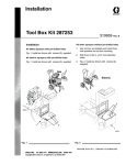
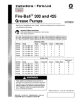
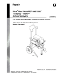
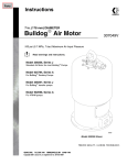
Instructions – Parts List Pro-Shot Grease Dispense Valve Service Kit 309119D Part No. 243446 Used on Models 242055, 242056, 242057, and 242058 10 1 11 4 6 5 2 9 8 7 6 3 TI0629B Ref. No. Description 1 2 3 4 5 6 NUT, self-locking; 10–32 BALL, carbide SPRING, compression SEAL NUT, hex; 10–32 GASKET; copper Qty. 2 1 1 1 2 2 GRACO INC.ąP.O. BOX 1441ąMINNEAPOLIS, MNą55440-1441 Copyright 2000, Graco Inc. is registered to I.S. EN ISO 9001 Ref. No. Description 7 8 9 10 11 PLUNGER/ROD ASSY. SEAT, valve YOKE SHAFT, pivot GUIDE, rod Qty. 1 1 1 2 1 Installation See instruction manual 309032 for troubleshooting guide. Replace all parts included in this service kit, checking all parts thoroughly when disassembling, and carefully replace any additional parts that are worn or damaged. Adjustment 2. To adjust the clearance, loosen the top nut (Fig. 1, item 5) and turn the bottom nut (5) in or out as needed. Hold the bottom nut in place and securely tighten the top nut. WARNING To reduce the risk of serious injury whenever you are instructed to relieve pressure, always follow the Pressure Relief Procedure in instruction manual 309032. 3. For less than maximum flow, back off bottom nut (5). 1. Relieve the pressure. 1 5 Yoke Rod Guide 1 Turn adjusting nut (5) down until yoke bottoms out on rod guide or until resistance is noticeably greater (max flow setting) Torque 80 – 100 ft. lbs. Fig. 1 TI0628 All information, illustrations and specifications in this document are based on the latest product information available at the time of publication. The right is reserved to make changes at any time without notice. Sales Offices: Minneapolis, Detroit International Offices: Belgium, Korea, Hong Kong, Japan www.graco.com PRINTED IN U.S.A. 309119 01/2000, Revised 02/2002 2 309119