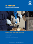
1
Instructions–Parts List
HIGH PRESSURE, STAINLESS STEEL, WATERBASE COMPATIBLE
Back Pressure Valve with Carbide
Needle and Seat
307892K
For use in air–assisted circulating system to control back pressure
to the gun(s) and maintain proper pressure for circulation. Also for
use with XM proportioners as an adjustable restriction valve.
For professional use only.
7250 psi (50 MPa, 500 bar) Maximum Fluid Inlet Pressure
150 – 7250 psi (1 – 50 MPa, 10 – 500 bar) Fluid Back Pressure Range
Part No. 222200, Series D
Important Safety Instructions
Read all warnings and instructions in this manual.
Save these instructions.
Table of Contents
Warnings . . . . . . . . . . . . . . . . . . . . . . . . . . . . . . . . 2
Installation . . . . . . . . . . . . . . . . . . . . . . . . . . . . . . . 3
Operation . . . . . . . . . . . . . . . . . . . . . . . . . . . . . . . 4
Cleaning and Maintenance . . . . . . . . . . . . . . . . 6
Parts . . . . . . . . . . . . . . . . . . . . . . . . . . . . . . . . . . . 7
Accessories . . . . . . . . . . . . . . . . . . . . . . . . . . . . . 7
Technical Data . . . . . . . . . . . . . . . . . . . . . . . . . . . 7
Dimensions . . . . . . . . . . . . . . . . . . . . . . . . . . . . . . 8
Performance Chart . . . . . . . . . . . . . . . . . . . . . . . 9
Warranty . . . . . . . . . . . . . . . . . . . . . . . . . . . . . . . 10
Graco Information . . . . . . . . . . . . . . . . . . . . . . . 10
ENG
WARNING
EQUIPMENT MISUSE HAZARD
Equipment misuse can cause the equipment to rupture or malfunction and result in serious injury.
INSTRUCTIONS
D This equipment is for professional use only.
D Read all instruction manuals, tags, and labels before operating the equipment.
D Use the equipment only for its intended purpose. If you are not sure, call Graco Technical Assistance at 1–800–543–0339.
D Do not alter or modify this equipment.
D Check equipment daily. Repair or replace worn or damaged parts immediately.
D Do not exceed the maximum working pressure of the lowest rated system component. The maximum working pressure of this equipment is 5000 psi (350 bar).
D Use fluids and solvents which are compatible with the equipment wetted parts. Refer to the Technical Data section of all equipment manuals. Read the fluid and solvent manufacturer’s warnings.
D Wear hearing protection when operating this equipment.
D Comply with all applicable local, state, and national fire, electrical, and safety regulations.
SKIN INJECTION HAZARD
Spray from the gun, leaks or ruptured components can inject fluid into your body and cause extremely
serious injury, including the need for amputation. Fluid splashed in the eyes or on the skin can also
cause serious injury.
D Fluid injected into the skin might look like just a cut, but it is a serious injury. Get immediate
surgical treatment.
D Follow the Pressure Relief Procedure on page 5 if the spray tip clogs and before cleaning,
checking or servicing the equipment.
D Do not stop or deflect leaks with your hand, body, glove or rag.
D Be sure all equipment safety devices are operating properly before each use.
2
307892
Installation
NOTE: The Typical Installations shown in Fig. 1 are
only guides for selecting and installing a circulating
system. Contact your Graco representative or Graco
Technical Assistance (see back page) for assistance in
designing a system to meet your particular needs.
Install the back pressure valve (K) in the spray gun
return line (L) as shown in the Typical Installation
drawing below or at right. Using pipe sealant on pipe
threads, connect the lines to the 3/8 npt(f) inlet and
outlet. Be sure the flow direction agrees with the
markings on the valve housing.
J
If more than one spray station is used, install a back
pressure valve (K) in the circulating line (M), after the
last spray station to maintain proper system pressures.
C
A
NOTE: The two 1/4–20 tapped mounting holes on the
side of the valve housing are for mounting the valve
when flexible fluid lines are used.
B
K
L
G
The back pressure valve was tested in lightweight oil.
Flush the entire system with a solvent compatible with
the fluid being sprayed or dispensed, then test the
system.
F
H
CAUTION
D
Single Circulating Spray Station
The new system must be cleaned and tested thoroughly before admitting fluid to the back pressure
valve, to avoid contaminants clogging or damaging
the valve.
M
E
F
K
J
C
KEY
A
B
C
D
E
F
G
H
Air Regulator
Bleed-Type Master Air Valve
Pump
Fluid Filter & Drain Valve
Main Fluid Supply Line
Gun Fluid Supply Line
Fluid Regulator
Fluid Pressure Gauge
& Drain Valve
J Air-Assisted Airless Spray Gun
K Back Pressure Valve
L Fluid Return Line
M Main Circulating Line
N Fluid Supply Container
A B
L
L
K
K
H
D
N
G
Multiple Circulating Spray Station
Fig. 1
307892
3
Operation
NOTE: The back pressure valve controls pressure
ahead of the valve inlet. When used with XM proportioners, the it controls the flow across the valve.
3. Adjust the pump air pressure and the back pressure valve for the best spraying combination and
the proper circulation of fluid. Use the lowest
possible air and fluid pressures for your application.
1. Back the adjusting screw out to allow full fluid flow.
4. Tighten the locking nut (3) to lock the setting.
5. Record all the settings for future reference.
2. Turn the screw clockwise to increase the back
pressure (less flow) and counterclockwise to
decrease it (more flow).
4
307892
NOTE: See the XM Mix Manifold Kits manual for more
information about how the valve operates as a machine mounted restrictor valve.
Cleaning and Maintenance
Pressure Relief Procedure
Cleaning
WARNING
SKIN INJECTION HAZARD
The system pressure must be manually
relieved to prevent the system from
starting or spraying accidentally. Fluid
under high pressure can be injected through the
skin and cause serious injury. To reduce the risk of
an injury from injection, splashing fluid, or moving
parts, follow the Pressure Relief Procedure
whenever you:
D
D
D
D
are instructed to relieve the pressure,
stop spraying,
check or service any of the system equipment,
or install or clean the spray tip.
1. Lock the gun trigger safety and other equipment
safety locks.
2. Turn off the power to the pump.
WARNING
To reduce the risk of serious injury whenever you
are instructed to relieve pressure, always follow the
Pressure Relief Procedure at left.
Flush the back pressure valve whenever the rest of the
system is flushed. Before flushing, relieve pressure,
then open the valve by turning the adjusting screw
counterclockwise to open the valve.
Before removing the back pressure valve for thorough
cleaning and inspection, relieve pressure. Then
remove the valve and clean and inspect all parts.
3. Unlock the gun trigger safety.
4. Hold a metal part of the gun firmly to the side of a
grounded metal pail, and trigger the gun to relieve
pressure.
5. Lock the gun trigger safety.
6. Open the drain valve (required in your system),
having a container ready to catch the drainage.
CAUTION
Do not allow paint or solvent to set in the system for
any extended length of time. Fluid could dry on the
valve stem, causing leakage at the stem packing. If
leakage occurs, disassemble and clean the valve.
7. Leave the drain valve open until you are ready to
spray again.
If you suspect that the spray tip or hose is completely
clogged, or that pressure has not been fully relieved
after following the steps above, very slowly loosen the
tip guard retaining nut or hose end coupling and relieve
pressure gradually, then loosen completely. Now clear
the tip or hose.
CAUTION
Handle the hard carbide parts, valve stem tip (2) and
seat (10), carefully to avoid damaging them. Damage
will cause poor operation and leakage.
307892
5
Cleaning and Maintenance
Seat and Valve Stem Replacement
(See the Parts Drawing on page 7)
5. Remove the locking nut (3) from the valve
stem (2).
NOTE: Order Kit No. 223016 to repair the back pressure valve.
6. Remove the valve stem (2).
WARNING
To reduce the risk of serious injury whenever you
are instructed to relieve pressure, always follow the
Pressure Relief Procedure on page 5.
7. Clean and inspect all parts. Replace all o-rings
with those provided in Kit No. 223016. Be sure to
lubricate all the o-rings and the spring.
8. Install o-rings (4 and 13) on the valve stem (2).
Install the stem into the valve housing (1).
9. Install the valve stop (5) over the tip of the valve
stem (2).
1. Relieve the pressure. Then remove the back
pressure valve from the fluid line.
10. Install retaining ring (6) into the valve housing (1).
2. Unscrew the seat housing (11) from the valve
housing (1).
11. Slide the o-ring (9) onto the valve seat (10). Install
the valve seat into the valve housing (1), with its
inside chamfer facing towards the valve stem (2).
3. Remove the valve seat (10), spring (8), and o-rings
(7, 9) from the seat housing (11).
4. Remove the retaining ring (6) and valve stop (5)
from the valve housing (1).
6
307892
12. Grease the spring (8) and install it into the seat
housing (11). Install the o-ring (7) on the seat
housing. Apply sealant to the seat housing threads
and screw it into the valve housing (1). Torque to
30–35 ft-lbs (41–47 NSm).
Parts
Ref.
No.
Part No.
Description
1
2*
3
4*
5
6
7*
8
9*
10*
11
12Y
187883
235205
110005
110004
188013
188003
110135
111738
104319
183951
187884
185052
HOUSING, valve
STEM, valve
NUT, hex jam; 5/16–24 UNF
O-RING, PTFE
STOP, valve
RING, retainer
O-RING, PTFE
SPRING, compression
O-RING, PTFE
SEAT, valve
HOUSING, seat
LABEL, warning (not shown)
3
Qty.
1
1
1
1
1
1
1
1
1
1
1
1
1
13*
113137
O-RING, CU–75
1
* These parts are included in Repair Kit 223016, which may
be purchased separately.
4
Y Replacement Danger and Warning labels, tags and cards
are available at no cost.
1
Torque to 30–35 ft-lb
(41–47 NSm).
2
Accessories
*2
3
Install with larger opening
facing up.
Lubricate.
4
Apply thread lubricant.
Bracket Kit 222515
To attach back pressure valve to cart, pail, or wall units.
Technical Data
Maximum fluid input pressure . . . . . . . . . . 7250 psi (500 bar)
Back pressure range . . . . . . . . . . 150–5000 psi (10–350 bar)
Maximum flow capacity . . . . . . . . . . . . . . . 4.5 gpm (17 lpm) at
135 centipoise fluid viscosity
Weight . . . . . . . . . . . . . . . . . . . . . . . . . . . . . . . . 2.35 lb (1.06 kg)
Wetted parts . . . . . PTFE, CU–75, 304 & 316 Stainless Steel,
17–7 ph Stainless Steel, Tungsten Carbide
3
Black
*13
3
White
*4
5
6
2
*10
3
8
3
*7
3
*9
11
1
4
307892
7
Dimensions
1/4–20
UNC–2B
Bracket
Holes
3/8–18 npt
Inlet & Outlet
4.75 in.
(120.7 mm)
2.5 in.
(63.5 mm)
0.87 in.
(22.1 mm)
1.99 in.
(50.5 mm)
1.3 in.
(33 mm)
OUT
Bracket
Holes
BOTTOM VIEW
8
307892
Performance Chart
TEST MEDIA: 65 centipoise
l/min. GPM
4.5
FLUID FLOW
15
KEY
4.0
A 5000 psi (350 bar)
B 2000 psi (140 bar)
3.5
C 1000 psi (70 bar)
3.0
10
D 300 psi (21 bar)
2.5
A
B
C
D
2.0
1.5
5
1.0
0.5
0.0
0.0
0.5
1.0
1.5
2.0
2.5
3.0
3.5
4.0
NUMBER OF TURNS
307892
9
The Graco Warranty and Disclaimers
WARRANTY
Graco warrants all equipment manufactured by it and bearing its name to be free from defects in material and workmanship on
the date of sale to the original purchaser for use. As purchaser’s sole remedy for breach of this warranty, Graco will, for a period
of twelve months from the date of sale, repair or replace any part of the equipment proven defective. This warranty applies only
when the equipment is installed, operated and maintained in accordance with Graco’s written recommendations.
This warranty does not cover, and Graco shall not be liable for, any malfunction, damage or wear caused by faulty installation,
misapplication, abrasion, corrosion, inadequate or improper maintenance, negligence, accident, tampering, or substitution of
non–Graco component parts. Nor shall Graco be liable for malfunction, damage or wear caused by the incompatibility with Graco
equipment of structures, accessories, equipment or materials not supplied by Graco, or the improper design, manufacture, installation, operation or maintenance of structures, accessories, equipment or materials not supplied by Graco.
This warranty is conditioned upon the prepaid return of the equipment claimed to be defective to an authorized Graco distributor
for verification of the claim. If the claimed defect is verified, Graco will repair or replace free of charge any defective parts. The
equipment will be returned to the original purchaser transportation prepaid. If inspection of the equipment does not disclose any
defect in material or workmanship, repairs will be made at a reasonable charge, which charges may include the costs of parts,
labor and transportation.
DISCLAIMERS AND LIMITATIONS
The terms of this warranty constitute purchaser’s sole and exclusive remedy and are in lieu of any other warranties (express or
implied), including warranty of merchantability or warranty of fitness for a particular purpose, and of any non–contractual
liabilities, including product liabilities, based on negligence or strict liability. Every form of liability for direct, special or consequential damages or loss is expressly excluded and denied. In no case shall Graco’s liability exceed the amount of the purchase price.
Any action for breach of warranty must be brought within two (2) years of the date of sale.
EQUIPMENT NOT COVERED BY GRACO WARRANTY
Graco makes no warranty, and disclaims all implied warranties of merchantability and fitness for a particular purpose, with
respect to accessories, equipment, materials, or components sold but not manufactured by Graco. These items sold, but not
manufactured by Graco (such as electric motor, switches, hose, etc.) are subject to the warranty, if any, of their manufacturer.
Graco will provide purchaser with reasonable assistance in making any claim for breach of these warranties.
Graco Information
For the latest information about Graco products, visit www.graco.com.
TO PLACE AN ORDER, contact your Graco distributor or call to identify the distributor closest to you:
Phone: 612–623–6921 or Toll Free: 1–800–328–0211 Fax: 612–378–3505
All written and visual data contained in this document reflects the latest product information available at the time of publication.
Graco reserves the right to make changes at any time without notice.
Original instructions. This manual contains English. MM 307892
Graco Headquarters: Minneapolis
International Offices: Belgium, China, Japan, Korea
GRACO INC. P.O. BOX 1441 MINNEAPOLIS, MN 55440–1441
Copyright 1998, Graco Inc. is registered to ISO 9001
www.graco.com
Revised 07/2010
10 307892