1
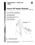
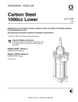
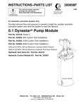
Instructions--Parts List
HIGH PRESSURE, MEDIUM VOLUME
“red alert” Filters
307252P
EN
For filtration of common industrial paints and coatings in finishing
applications. For professional use only.
3000 psi (21.0 MPa, 210 bar) Maximum Working Pressure
10 gpm (38 liter/min) Flow Capacity
36 sq. in. (230 cm 2) Filtering Area
Part No. 210090, 60 mesh (250 micron) element 108116
Part No. 210091, 100 mesh (149 micron) element 108117
Part No. 210092, 200 mesh (74 micron) element 108118
Part No. 104435, without element
Important Safety Instructions
Read all warnings and instructions in this manual.
Save these instructions.
03731
WARNINGS
High Pressure Spray Can Cause Serious Injury. Observe All Warnings.
Read and understand all instruction manuals before operating equipment.
SKIN INJECTION HAZARD
General Safety
Pressure Relief Procedure
This equipment is used in a system which generates very high
fluid pressure. Spray from leaks or ruptured components can inject fluid through your skin and into your body and cause extremely serious bodily injury, including the need for amputation.
Also, fluid injected or splashed into the eyes or on the skin can
cause serious damage.
To reduce the risk of serious bodily injury, including fluid injection, splashing in the eyes or on the skin, or injury from moving
parts, always follow this procedure whenever you install,
remove, clean or repair any part of the system.
1.
Engage the spray gun safety latch and any other equipment safety locks.
2.
Shut off the air or hydraulic supply to the pump.
3.
Disengage the gun safety latch.
4.
Hold a metal part of the gun firmly to the side of a grounded
metal pail, and trigger the gun to relieve pressure.
5.
Engage the gun safety latch.
6.
Keeping your hands away from the end of the drain valve,
slowly open the drain valves (required in your system) having a container ready to catch the drainage.
7.
Leave the drain valves open until you are ready to use the
system again.
Never try to stop or deflect leaks with your hand or body.
Keep hands away from the end of the drain valve when opening
the drain valve.
Medical Alert -- Airless Spray Wounds
If any fluid appears to penetrate your skin, get immediate
surgical treatment. Do not treat as a simple cut. Tell the
doctor exactly what fluid was injected.
NOTE TO PHYSICIAN: Injection into the skin is a traumatic
injury. It is important to treat the injury surgically as soon
as possible. Do not delay treatment to research toxicity. Toxicity is a concern with some exotic coatings injected directly
into the blood stream. Consultation with a plastic surgeon or
reconstructive hand surgeon may be advisable.
EQUIPMENT MISUSE HAZARD
General Safety
System Pressure
Any misuse of the equipment or accessories, such as
overpressurizing, modifying parts, using incompatible chemicals and fluids, or using worn or damaged parts, can cause
them to rupture and result in fluid injection, splashing in the eyes
or on the skin, or other serious bodily injury, or fire, explosion or
property damage.
Do not exceed 3000 psi (210 bar) Maximum Working Pressure,
or the maximum working pressure of the lowest rated component or accessory in your system.
Be sure all components and accessories are rated to withstand
the maximum working pressure of your pump.
Never alter or modify any part of this equipment; doing so could
cause it to malfunction.
Be sure that all fluids and solvents used are chemically compatible with the wetted parts shown in the Technical Data on
page 5 and in all other components used in the system.
2
307252
Fluid Compatibility
Installation
To clean or service the filter without shutting down the system,
install a dual filter or a filter bypass system as explained below.
The numbers and letters in parentheses refer to Figs. 1, 2, and
3 and the Parts Drawing. Accessories and Technical Data are
on the page 5.
IN
OUT
NOTE: Allow 3 in. (76 mm) minimum clearance below the filter
for easy removal of the bowl (10).
D
10
A,B
Fluid Drain Valve (required in all systems)
WARNING
A fluid drain valve is required in the base of each fluid filter.
Use this drain valve to relieve fluid pressure in the filter, to
reduce the risk of serious injury, including fluid injection and
splashing in the eyes or on the skin.
D
03710
Filter Bypass System
Fig. 1
Remove the 3/4 unf plug (12) from the bottom of the filter and
install a high pressure adapter and drain valve (A,B). See Fig.
2.
10
Dual Filter System
This setup enables you to redirect the fluid to another filter while
one filter is cleaned or serviced.
Install two filters as shown in Fig. 2. Install four suitable shutoff
valves (D), one at each filter and outlet, to redirect the fluid and
isolate the filter not in use.
D
A,B
D
IN
OUT
Filter Bypass System
Install the filter and bypass pipes as shown in Fig. 1. Install four
suitable shutoff valves (D), one each at the filter inlet, the filter
outlet, the bypass pipe inlet, and the bypass pipe outlet. These
valves redirect the fluid and isolate the filter while cleaning and
servicing.
D
10
A,B
D
This setup enables you to redirect the fluid through pipes which
bypass the filter while cleaning or servicing the filter.
Dual Filter System
Fig. 2
03709
Dimensions
Mounting Dimensions
Basic Overall Dimensions
4.5 in.
(11.43 cm)
3/8--16 UNC
2X 2.5 in.
(6.35 cm)
8.16 in.
(20.73 cm)
11.3 in.
(28.7 cm)
2X .39 in
(.99 cm)
2X 1.5 in.
(3.81 cm)
2X 3.0 in.
(7.62 cm)
TI15744a
TI15743a
307252
3
Service
CAUTION
If the filter will not be used for a while, thoroughly clean all
the parts in solvent and blow them dry before the paint dries
and clogs the filter. To help prevent damaging the parts, do
not clean them with a wire brush or sharp object.
Indicator
The indicator provides gradual warning of a dirty element. When
the indicator shows 3/4 red, clean the element. If not cleaned
promptly, the filter bypass valve opens and fluid will not be
filtered.
Replace the indicator assembly (1) if the indicator is not working
correctly (it is always red or never red). See Fig. 3.
drying on the housing (3) and other parts. Install the element
with the dome end up. Lubricate the threads of the bowl before
screwing it into the housing. Tighten it securely.
Clean the bowl, element and spring you removed with a
compatible solvent before the paint dries. Do not use a wire
brush or sharp object to clean. Store until needed.
NOTE: Clean the filter element (8) with a small paint brush. Blow
out lodged particles with air, and inspect for damage. Replace
if ruptured, damaged or too dirty to clean.
1
3/4” npt(f) Inlet
and outlet
2
3/4--16 unf (f)
drain port
1
Bypass Valve
The valve opens when a dirty element causes the filter’s outlet
pressure to drop 15 psi (1 bar) below the inlet pressure. This
keeps the system pressure steady and prevents the element
from collapsing.
3
2
1
Replace the bypass valve (2) if it is damaged or worn.
Fluoroelastomer O-Ring and O-Ring Backup
6
7
The o-rings seal the bowl (10) to the housing (3). If material
leaks around the bowl, replace the o-ring (6) and o-ring backup
(7).
Follow the Pressure Relief Procedure on page 2. Remove the
bowl and o-rings. Clean the parts in a compatible solvent. Be
careful not to damage the o-ring or sealing surfaces of the bowl
and housing. Before assembling, lubricate the parts with No. 2
grease. Be sure the o-ring backup is installed with the groove
facing up.
8
9
Bowl, Element and Spring
To reduce downtime, keep a spare bowl (10), element (8) and
spring (9) on hand. Before removing the bowl, direct the fluid
through the bypass pipes or shut down the system. Relieve fluid
pressure by opening the drain valve (B). Have a container ready
to catch the drainage.
Remove the bowl, element and spring. Replace immediately
with the spare bowl, element and spring to keep the paint from
4
307252
10
12
2
Fig. 3
03730
Parts
Model No. 210090 to 210092
Includes items 1 to 12.
1
3/4” npt(f) Inlet
and outlet
2
3/4--16 unf (f)
drain port
Model No. 104435
Includes items 1 to 7, 9 to 12;
Order the filter element separately from
those listed under Ref. No. 8.
3
Ref.
No.
Part No.
1
2
3n
6n
104125
104440
104441
104445
7n
104443
8n
108116
108117
108118
9n
10n
11n
12
1
104438
104439
104444
104126
Description
INDICATOR, filter
VALVE, bypass
HOUSING, filter
O--RING, fluoroelastomer
See Accessories for ethylene-propylene o--ring
BACKUP, o--ring, fluoroelastomer
See Accessories for PTFE backup
ELEMENT, filter,
60 mesh (250 micron
(for Model 210090 only)
ELEMENT, filter,
100 mesh (149 micron)
(for Model 210091 only)
ELEMENT, filter,
200 mesh (74 micron)
(for Model 210092 only)
SPRING, element
BOWL, filter
O--RING, fluoroelastomer
PLUG; 3/4--16 unf
2
Qty.
1
1
1
1
1
6
7
1
8
1
9
1
1
1
1
1
1
n Keep these spare parts on hand to reduce downtime.
10
11
03730
2
12
Accessories
Technical Data
Replacement Indicator O--Rings
109576
small (#016), fluoroelastomer
or 104093
small (#016), buna
104130
large (#119), buna
Conversion O-Rings
For use with fluids not compatible with fluoroelastomer.
105280
O-ring, Ethylene-Propylene
105279
Backup o-ring, PTFE
Maximum Working Pressure . . . . . . 3000 psi (210 bar)
Flow Capacity . . . . . . . . . . . . . . . . 10 gpm (38 liters/min)
Filter Area . . . . . . . . . . . . . . . . . . . . . 36 sq. in. (232 cm2)
Wetted Parts . . . . . . . . . . Iron, Steel, Fluoroelastomer,
Stainless Steel
Dimensions . . . . . . . . . . . . . . . . . . . 4.5” (114 mm) width
4.62” (117 mm) depth
11.3” (287 mm) height
Weight . . . . . . . . . . . . . . . . . . . . . . . . 14 lb 8 oz. (6.6 kg)
Adapter 105276
3000 psi (210 bar) Maximum Working Pressure
3/4--16 unf thread x 1/4 npt
Adapts bowl to accept drain valves listed below.
Drain Valves
5000 psi (350 bar) Maximum Working Pressure
Install in adapter 105276 for relieving fluid pressure in
filter
210657
1/4 npt(mbe) fluoroelastomer seals
214037
1/4 npt(mbe) PTFE seals
307252
5
The Graco Warranty and Disclaimers
WARRANTY
Graco warrants all equipment manufactured by it and bearing its name to be free from defects in material and workmanship on the date of sale to the
original purchaser for use. As purchaser’s sole remedy for breach of this warranty, Graco will, for a period of twelve months from the date of sale, repair
or replace any part of the equipment proven defective. This warranty applies only when the equipment is installed, operated and maintained in accordance
with Graco’s written recommendations.
This warranty does not cover, and Graco shall not be liable for, any malfunction, damage or wear caused by faulty installation, misapplication, abrasion,
corrosion, inadequate or improper maintenance, negligence, accident, tampering, or substitution of non--Graco component parts. Nor shall Graco be
liable for malfunction, damage or wear caused by the incompatibility with Graco equipment of structures, accessories, equipment or materials not supplied by Graco, or the improper design, manufacture, installation, operation or maintenance of structures, accessories, equipment or materials not supplied by Graco.
This warranty is conditioned upon the prepaid return of the equipment claimed to be defective to an authorized Graco distributor for verification of the
claim. If the claimed defect is verified, Graco will repair or replace free of charge any defective parts. The equipment will be returned to the original purchaser transportation prepaid. If inspection of the equipment does not disclose any defect in material or workmanship, repairs will be made at a reasonable
charge, which charges may include the costs of parts, labor and transportation.
DISCLAIMERS AND LIMITATIONS
The terms of this warranty constitute purchaser’s sole and exclusive remedy and are in lieu of any other warranties (express or implied), including
warranty of merchantability or warranty of fitness for a particular purpose, and of any non--contractual liabilities, including product liabilities, based
on negligence or strict liability. Every form of liability for direct, special or consequential damages or loss is expressly excluded and denied. In no case
shall Graco’s liability exceed the amount of the purchase price. Any action for breach of warranty must be brought within two (2) years of the date of sale.
EQUIPMENT NOT COVERED BY GRACO WARRANTY
Graco makes no warranty, and disclaims all implied warranties of merchantability and fitness for a particular purpose, with respect to accessories,
equipment, materials, or components sold but not manufactured by Graco. These items sold, but not manufactured by Graco (such as electric motor,
switches, hose, etc.) are subject to the warranty, if any, of their manufacturer. Graco will provide purchaser with reasonable assistance in making any
claim for breach of these warranties.
Graco Information
For the latest information about Graco products, visit www.graco.com.
For patent information, see www.graco.com/patents.
TO PLACE AN ORDER, contact your Graco distributor or call to identify the nearest distributor.
Phone: 612--623--6921 or Toll Free: 1--800--328--0211 Fax: 612--378--3505
All written and visual data contained in this document reflects the latest product information available at the time of publication.
Graco reserves the right to make changes at any time without notice.
Original instructions. This manual contains English. MM 307252
Graco Headquarters: Minneapolis
International Offices: Belgium, China, Japan, Korea
6
GRACO INC. AND SUBSIDIARIES P.O. BOX 1441 MINNEAPOLIS MN 55440--1441 USA
Copyright 1976, Graco Inc. All Graco manufacturing locations are registered to ISO 9001.
www.graco.com
Revision P, May 2014
307252