1
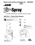
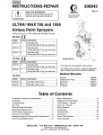
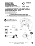
REPAIR
309063F
Important Safety Instructions
Read all warnings and instructions in this
manual. Save these instructions.
First choice when
quality counts.t
- For portable spray applications of architectural paints and coatings -
190ESt
Airless Paint Sprayers
3000 psi (207 bar, 20.7 MPa ) Maximum Working Pressure
120 VAC
232900, A, B, C, D, E, F
232901, A, B, C, D, E
233797, A, B, C, D, E
233815, A, B, C, D, E
100--120 VAC
232903, A, B
220--240 VAC
ti7400a
232906, A, B
232900
. . . . . . . 309365
. . . . . . . 309060
. . . . . . . 309045
. . . . . . . . . . . . . . . . . . . . . 309064
. . . . . . . 309065
Table of Contents
Component Function and Identification . . . . . . . . . . . . 5
Pressure Relief Procedure . . . . . . . . . . . . . . . . . . . . . . . 6
General Repair Information . . . . . . . . . . . . . . . . . . . . . . 7
Grounding . . . . . . . . . . . . . . . . . . . . . . . . . . . . . . . . . . . . . 8
Troubleshooting . . . . . . . . . . . . . . . . . . . . . . . . . . . . . . . . 9
Spin Test . . . . . . . . . . . . . . . . . . . . . . . . . . . . . . . . . . . . . 12
Motor Brush Replacement . . . . . . . . . . . . . . . . . . . . . 12
On/Off Switch Replacement . . . . . . . . . . . . . . . . . . . . 14
Pressure Control Repair . . . . . . . . . . . . . . . . . . . . . . . 19
Drive Housing Replacement . . . . . . . . . . . . . . . . . . . . 24
Motor Replacement . . . . . . . . . . . . . . . . . . . . . . . . . . . . 25
Displacement Pump Replacement . . . . . . . . . . . . . . . 26
Technical Data . . . . . . . . . . . . . . . . . . . . . . . . . . . . . . . . 27
Graco Phone Number . . . . . . . . . . . . . . . . . . . . . . . . . . 28
Graco Warranty . . . . . . . . . . . . . . . . . . . . . . . . . . . . . . . 28
Specifications
This equipment is not intended for use with flammable or combustible materials used in places such as
cabinet shops or other “factory” or fixed locations. If you intend to use this equipment in this type of
application, you must comply with NFPA 33 and OSHA requirements for the use of flammable and
combustible materials.
Warnings
Warning Symbol
WARNING
This symbol alerts you to the possibility of serious
injury or death if you do not follow the instructions.
2
309063
Caution Symbol
CAUTION
This symbol alerts you to the possibility of damage to
or destruction of equipment if you do not follow the
instructions.
The following are general Warnings related to the safe setup, use, maintenance and repair of this equipment.
Additional, more specific warnings may be found throughout the text of this manual where applicable.
WARNING
FIRE AND EXPLOSION HAZARD
Flammable fumes, such as solvent and paint fumes, in work area can ignite or explode. To help
prevent fire and explosion:
D Use equipment only in well ventilated area.
D When flammable liquid is used in or near sprayer or for flushing or cleaning, keep sprayer at least
20 feet (6 m) away from explosive vapors.
D Eliminate all ignition sources; such as pilot lights, cigarettes, portable electric lamps, and plastic
drop clothes (potential static arc).
D Keep work area free of debris, including solvent, rags and gasoline.
D Do not plug or unplug power cords, or turn lights on or off when flammable fumes are present.
D Ground equipment and conductive objects in work area. See Grounding instructions.
D Use only grounded hoses.
D Hold gun firmly to side of grounded pail when triggering into pail.
D If there is static sparking or you feel a shock, stop operating immediately. Do not use equipment
until you identify and correct the problem.
D Keep a fire extinguisher in the work area.
ELECTRIC SHOCK HAZARD
Improper grounding, setup, or usage of the system can cause electric shock.
D Turn off and disconnect power cord before servicing equipment.
D Use only grounded electrical outlets
D Use only 3--wire extension cords.
D Ensure ground prongs are intact on sprayer and extension cords.
SKIN INJECTION HAZARD
High pressure fluid from gun, hose leaks, or ruptured components will pierce skin. This may look like
just a cut, but it is a serious injury that can result in amputation. Get immediate surgical treatment.
D Do not point gun at anyone or any part of the body.
D Do not put your hand over the spray tip.
D Do not stop or deflect leaks with your hand, body, glove, or rag.
D Do not spray without tip guard and trigger guard installed.
D Engage trigger lock when not spraying.
D Follow Pressure Relief Procedure in this manual, when you stop spraying and before cleaning,
checking or servicing equipment.
309063
3
EQUIPMENT MISUSE HAZARD
Misuse can cause death or serious injury.
INSTRUCTIONS
D Do not exceed the maximum working pressure or temperature rating of the lowest rated system
component. Read Technical Data in all equipment manuals.
D Use fluids and solvents that are compatible with equipment wetted parts. Read Technical Data in
all equipment manuals. Read fluid and solvent manufacturer’s warnings.
D Check equipment daily. Repair or replace worn or damaged parts immediately.
D Do not alter or modify equipment.
D Use equipment only for its intended purpose. Call your Graco distributor for information.
D Route hoses and cables away from traffic areas, sharp edges, moving parts and hot surfaces.
D Do kink or overbend hoses or use hoses to pull equipment.
D Keep children and animals away from work area.
D Comply with all applicable safety regulations.
PRESSURIZED ALUMINUM PARTS HAZARD
Do not use 1,1,1-trichloroethane, methylene chloride, other halogenated hydrocarbon solvents or
fluids containing such solvents in pressurized aluminum equipment. Such use can cause serious
chemical reaction and equipment rupture, and result in death, serious injury, and property damage.
BURN HAZARD
Equipment surfaces can become very hot during operation. To avoid sever burns, do not touch hot
equipment. Wait until equipment has cooled completely.
TOXIC FLUID HAZARD
Toxic fluid or fumes can cause serious injury or death if splashed in the eyes or on skin, inhaled, or
swallowed.
D Read MSDS’s to know the specific hazards of the fluids you are using.
D Store hazardous fluid in approved containers and dispose of it according to all applicable guidelines.
PERSONAL PROTECTIVE EQUIPMENT
You must wear appropriate protective equipment when operating, servicing, or when in the operating
area of the equipment to help protect you from serious injury, including eye injury, inhalation of toxic
fumes, burns, and hearing loss. This equipment includes, but is not limited to:
D Protective eye wear.
D Clothing and respirator as recommended by the fluid and solvent manufacturer.
D Gloves.
D Hearing protection.
MOVING PARTS HAZARD
Moving parts can pinch or amputate fingers and other body parts.
D Keep clear of moving parts.
D Do not operate equipment with protective guards or covers removed.
D Pressurized equipment can start without warning. Before checking, moving, or servicing equipment, follow the Pressure Relief Procedure in this manual. Disconnect power or air supply.
4
309063
Component Identification and Function
H
A
J
B
V
U
R
P
S
T
K
F
D
ti7400a
ti5914a
N
E
G
M
A
Motor
DC motor, permanent magnet, fan cooled
B
Drive Assembly
Transfers power from DC motor to displacement pump
D
Displacement Pump
Transfers fluid to be sprayed from source through spray gun
E
Fluid Outlet
Spray gun is connected here
F
Prime Valve
Used to prime and drain sprayer (also relieves fluid outlet pressure) when
open
G
Fluid Filter (optional)
Final filter of fluid to spray gun
H
Pressure Adjusting Knob
Controls fluid outlet pressure
J
Pressure Control
Controls motor speed to maintain fluid outlet pressure at displacement pump
outlet. Works with pressure adjusting knob.
K
ON/OFF Switch
Power switch that controls main power to sprayer
M
50 ft (15 m) Main Hose
1/4 in. ID, grounded, nylon hose with spring guards on both ends
N
Spray Gun
High pressure spray gun with gun safety latch
P
RAC IV Switch Tip
Uses high pressure fluid to clear tip clogs without removing tip from spray gun
R
Tip Guard
Tip guard reduces risk of injection injury
S
Thumb Lock Safety
Gun safety latch inhibits accidental triggering of spray gun
T
Power Cord Rack
Holds wrapped power cord for storage
U
Suction Hose
Transfers fluid to be sprayed from source to pump
V
Drain Tube
Fluid outlet used to drain and prime the sprayer
309063
5
Pressure Relief Procedure
WARNING
SKIN INJECTION HAZARD
Follow this Pressure Relief Procedure
whenever you are instructed to relieve
pressure, stop spraying, check or service equipment, or install or clean spray tip. read
Injection Hazard Warning.
1. Turn OFF power and turn pressure control to lowest pressure setting.
2. Hold gun against side of grounded metal flushing
pail. Trigger gun to relieve pressure.
Fig. 2
If suspected that spray tip or hose is clogged or that
pressure has not been fully relieved after following
steps above , VERY SLOWLY loosen tip guard retaining nut or hose end coupling to relieve pressure gradually, then loosen completely. Clear tip or hose obstruction.
4. Engage trigger safety lock on gun if unit is being
shut down or left unattended.
CAUTION
To reduce risk of pressure control malfunction:
D
Use needle nose pliers to disconnect wire. Never
pull on wire, pull on connector.
D
Mate wire connectors properly. Center flat blade of
insulated male connector in female connector.
D
Route wires carefully to avoid interference with
other connections of pressure control. Do not pinch
wires between cover and control box.
ti7401a
FLUSH
Fig. 1
3. Turn prime valve down
6
309063
General Repair Information
WARNING
Read Electric Shock Warning and
Burn Hazard Warning.
WARNING
To reduce risk of serious injury, including
electric shock:
D Do not touch moving or electric parts
with fingers or tools while testing repair
D Unplug sprayer when power is not
required for testing
WARNING
Flammable materials spilled on hot,
bare, motor could cause fire or
explosion. To reduce risk of burns, fire or
explosion, do not operate sprayer with
cover removed.
D Keep all screws, nuts, washers, gaskets, and
electrical fittings removed during repair procedures.
These parts usually are not provided with replacement kits.
D test repairs after problems are corrected.
D If sprayer does not operate properly, review repair
procedure to verify you did it correctly. See Troubleshooting, page 9.
D Overspray may build up in the air passages. Remove any overspray and residue from air passages
and openings in the enclosures whenever you
service sprayer.
D Do not operate the sprayer without the motor
shroud in place. replace if damaged. Motor shroud
directs cooling air around motor to prevent overheating and insulate the control board from accidental electric shock.
D Install all covers, gaskets, screws and
washers before you operate sprayer
CAUTION
D Do not run sprayer dry for more than 30 seconds.
Doing so could damage pump packings.
D Protect the internal drive parts of this sprayer
from water. openings in the cover allow for air
cooling of the mechanical parts and electronics
inside. If water gets in these openings, sprayer
could malfunction or be permanently damaged.
D Prevent pump corrosion and damage from freezing. Never leave water or water--base paint in
sprayer when it is not in use in cold weather.
Freezing fluids can seriously damage sprayer.
Store sprayer with Pump armour to protect sprayer during storage.
D Do not operate the sprayer without the motor
shroud or control box cover in place. Replace if
damaged. Motor shroud directs cooling air around
motor to prevent overheating and the control box
cover insulates the control board from accidental
electric shock.
309063
7
Grounding and Electric Requirements
WARNING
Your system must be grounded. Read
warnings, page 3.
ti7482a
Fig. 5
Recommended extension cords for use with this
sprayer:
The sprayer cord includes: a grounding wire with an
appropriate grounding contact.
D 110--120V: 3--wire, 12 AWG (2.5 mm2) minimum,
300 ft. (90 m) maximum length.
D 240V: 3--wire, 16 AWG (1.0 mm2) minimum, 300 ft.
(90 m) maximum length.
Smaller gauge or longer extension cords may
reduce sprayer performance.
ti7480a
Fig. 3
The sprayer requires:
110--120V units: 100--130 VAC, 50/60 Hz, 15A, 1
phase, circuit with a grounding receptacle.
240V Units: 210--255 VAC, 50/60 Hz, 7.5A, 1 phase,
circuit with a grounding receptacle.
Never use an outlet that is not grounded or an
adapter.
Spray gun: ground through connection to a properly
grounded fluid hose and pump.
Fluid supply container: follow local code.
Solvent and Oil--based fluids: follow local code. Use
only conductive metal pails placed on a grounded
surface such as concrete. Do not place the pail on a
nonconductive surface such as paper or cardboard,
which interrupts grounding continuity.
Grounding the metal pail: connect a ground wire to
the pail by clamping one end to pail and other end to
ground such as a water pipe.
To maintain grounding continuity when flushing
or relieving pressure: hold metal part of the spray
gun firmly to the side of a grounded metal pail, then
trigger the gun.
ti7481a
Fig. 4
Do not use the sprayer if the electrical cord has a
damaged ground contact. Only use an extension cord
with an undamaged ground contact.
8
309063
Fig. 6
ti7483a
Troubleshooting
Relieve pressure; page 6.
MOTOR WON’T OPERATE
TYPE OF PROBLEM
WHAT TO CHECK
If check is OK, go to next check
Basic Fluid Pressure
Problems
1. Pressure control knob setting. Motor will not run 1. Slowly increase pressure setting to see if moif at minimum setting (fully counterclockwise).
tor starts.
Basic Mechanical
Problems
WHAT TO DO
When check is not OK refer to this column
2. Spray tip or fluid filter may be clogged.
2. Relieve pressure and clear clog or clean filter; refer to separate gun or tip instruction
manual.
1. Pump (13) frozen or hardened paint.
1. Thaw sprayer if water or water-based paint
has frozen in sprayer. Place sprayer in warm
area to thaw. Do not start sprayer until
thawed completely. If paint hardened (dried)
in sprayer, replace pump packings. See
page 26 (Displacement Pump Replacement).
2. Displacement pump connecting rod pin (9a). 2. Push pin into place and secure with spring rePin must be completely pushed into connecting
tainer.
rod (9) and retaining spring (9b) must be firmly
in groove of pump pin. See Fig. 18.
3. Motor (1). Remove drive housing assembly 3. Replace motor (1) if fan won’t turn. See page
(10). See page 24. Try to rotate fan by hand.
25.
1. Motor control board. Board shuts down and dis- 1. See Motor Control Board Diagnostics,
Basic Electrical Problems
plays error code on some models.
page 19.
See Wiring
pages
g Diagram,
g
,p
g
15 to 18.
2. Electrical supply. Meter must read 100--130
2. Reset building circuit breaker; replace buildVAC for 110--120 VAC models and 210--255
ing fuses. Try another outlet.
VAC for 240 VAC models.
3. Extension cord. Check extension cord continu- 3. Replace extension cord.
ity with volt meter.
4. Sprayer power supply cord. Inspect for damage 4. Replace power supply cord.
such as broken insulation or wires.
5. Fuse. Check replaceable fuse on control board. 5. Replace fuse after completing motor inspection.
6. Motor leads are securely fastened and properly 6. Replace loose terminals; crimp to leads. Be
connected to control board.
sure terminals are firmly connected.
Clean circuit board terminals. Securely reconnect leads.
7. Motor thermal switch. Yellow motor leads must 7. Replace motor. See page 25, Motor Rehave continuity through thermal switch.
placement.
8. Brush cap missing or loose brush lead connec- 8. Install brush cap or replace brushes if leads
tions.
are damaged. See page 12, Motor Brush Replacement.
9. Brush length which must be 1/4 in. (6 mm) mini- 9. Replace brushes. See page 12, Motor Brush
mum.
Replacement.
NOTE: Brushes do not wear at the same rate on
both sides of motor. Check both brushes.
10.Motor armature commutator for burn spots, 10. Remove motor and have motor shop resurgouges and extreme roughness.
face commutator if possible. See page 25,
Motor Replacement.
11. Motor armature for shorts using armature tester 11. Replace motor. See page 25, Motor Re(growler) or perform spin test, page 12.
placement.
12.Pressure control not plugged in to control board. 12.Insert pressure control connector into control
board.
309063
9
Troubleshooting
LOW OR FLUCTUATING OUTPUT
TYPE OF PROBLEM
WHAT TO CHECK
If check is OK, go to next check
WHAT TO DO
When check is not OK refer to this column
Low Output
1. For worn spray tip.
1. Follow Pressure Relief Procedure Warning, then replace tip. See your separate
gun or tip manual.
2. Verify pump does not continue to stroke when 2. Service pump. See page 26.
gun trigger is released.
3. Filter clogged (If optional filter is installed).
3. Relieve pressure. Check and clean filter.
4. Prime valve leaking.
4. Relieve pressure. Repair prime valve.
5. Suction hose connections.
5. Tighten any loose connections.
6. Electrical supply with volt meter.
6. Reset building circuit breaker; replace
Meter must read:
building fuse. Repair electrical outlet or try
210--255 Vac for 220--240 Vac models.
another outlet.
85--130 Vac for 100--120 Vac models. Low voltages reduce sprayer performance.
7. Extension cord size and length; must be at least 7. Replace with a correct, grounded exten12 gauge wire and no longer than 300 ft. Longer
sion cord.
cord lengths reduce sprayer performance.
8. Leads from motor to pressure control circuit 8. Be sure male terminal blades are centered
board (35) for damaged or loose wires or conand firmly connected to female terminals.
nectors. Inspect wiring insulation and terminals
Replace any loose terminal or damaged
for signs of overheating.
wiring. Securely reconnect terminals.
9. For loose motor brush leads and terminals. See 9. Tighten terminal screws. Replace brushes
page 12.
if leads are damaged. See page 12.
10.For worn motor brushes which must be 1/4 in. (6 10. Replace brushes. See page 12.
mm) minimum. See page 12.
11. For broken or missing motor brush caps.
11. Replace brushcap if broken. Realign spring
with brush. See page 12.
12.Motor brushes for binding in brush holders. See 12.Clean brush holders, remove carbon dust
page 12.
with small cleaning brush. Align brush lead
with slot in brush holder to assure free vertical brush movement.
13.Low stall pressure.
13. Do either or both:
a. Turn pressure control knob fully
clockwise. Make sure pressure
control knob is properly installed to
allow full clockwise position.
b.
Try a new transducer.
14.Motor armature for shorts by using an armature 14.Replace motor. See page 25.
tester (growler) or perform spin test. See page
12.
10
309063
Troubleshooting
LOW OR FLUCTUATING OUTPUT
TYPE OF PROBLEM
WHAT TO CHECK
If check is OK, go to next check
WHAT TO DO
When check is not OK refer to this column
Motor runs and pump strokes
1. Paint supply.
1. Refill and reprime pump.
2. Intake strainer clogged.
2. Remove and clean, then reinstall.
3. Suction tube or fittings loose.
3. Tighten; use thread sealant or sealing tape
on threads if necessary.
4. To see if intake valve ball and piston ball are 4. Remove intake valve and clean. Check
seating properly. See page 26.
balls and seats for nicks; replace if necessary, page 26. Strain paint before using to
remove particles that could clog pump.
5. Leaking around throat packing nut which may 5. Replace packings, page 26. Also check
indicate worn or damaged packings. See
piston valve seat for hardened paint or
page 26.
nicks and replace if necessary. Tighten
packing nut/wet-cup.
6. Pump rod damage.
6. Repair pump, page 26.
7. Capacitor failure. Visually inspect capacitor 7. Replace capacitor.
near terminals. Ensure that orange safety relief plug is intact.
Motor runs but pump does not 1. Displacement pump pin (9a) (damaged or 1. Replace pump pin if missing. Be sure remissing), page 26.
tainer spring (9b) is fully in groove all
stroke
around connecting rod, page 26.
2. Connecting rod assembly (9) for damage, 2. Replace connecting rod assembly,
page 24.
page 24.
3. Gears or drive housing, page 24.
3. Inspect drive housing assembly and gears
for damage and replace if necessary,
page 24.
Motor is hot and runs intermit- 1. Be sure ambient temperature where sprayer 1. Move sprayer to shaded, cooler area if posis located is not more than 115 _F (46 _C) and
sible.
tently
sprayer is not located in direct sun.
2. Motor has burned windings indicated by re- 2. Replace motor. See page 25, Motor Removing positive (red) brush and seeing
placement.
burned adjacent commutator bars.
3. Tightness of pump packing nut. Overtighten- 3. Loosen packing nut. Check for leaking
ing tightens packings on rod, restricts pump
around throat. Replace pump packings if
action and damages packings.
necessary. See pump manual 309060.
309063
11
Spin Test
Setup
Armature, Brushes, and Motor Wiring Open
Circuit Test (Continuity)
Electric Shock Hazard; page 6.
To check armature, motor winding and brush electrical
continuity:
1.
Relieve pressure; page 6.
1. Connect red and black motor leads together with
test lead. Turn motor fan by hand at about two
revolutions per second.
2. If uneven or no resistance, check for: broken brush
springs, brush leads, motor leads; loose brush
terminal screws, motor lead terminals; worn
brushes. Repair as needed; page 12.
3. If still uneven or no resistance, replace motor;
page 25.
2. Remove drive housing; page 24.
3. Fig. 7. Remove pressure control cover (39). Disconnect red and black motor leads from control
board.
39
4. Fig. 8. Remove motor shroud (74).
F
G
Armature Short Circuit Test
Quickly turn motor fan by hand. If no electrical shorts,
motor coasts two or three revolutions before complete
stop. If motor does not spin freely, armature is
shorted. Replace motor; page 25.
9578A
Fig. 7
Motor Brush Replacement
Motor Brush Removal
Replace brushes worn to less than 1/4 in. (6 mm).
Check both sides. See Parts List 309064 for correct
brush kit for your series of sprayer.
74
1. Read General Repair Information; page 7.
2.
Relieve pressure; page 6.
3. Fig. 8. Remove four screws (18) and motor
shroud (74).
4. Pry off two brush caps (A). Tag locations of red (+)
and black (--) motor leads. Cut tie wrap.
5. Fig. 5. Remove screw (C) and discard brush (B)
for motor with capacitor attached. Remove brush
leads from control box for motor without capacitor
attached.
(Continued on page 13)
12
309063
18
Fig. 8
A
TI0053
Motor Brush Replacement
6. Fig. 9. Insert brush (B). Push cap (A) into place
over brush. Orient each cap with the 2 projections
on either side of the brush lead. You will hear a
“snap” when cap is securely in place.
CAUTION
When installing brushes, follow all steps carefully to
avoid damaging parts.
7. Fig. 9. Install red (+) and black (--) motor leads
according to tags. Install brush lead end with
screw (C) to motor-mounted capacitor or route
lead into control box and connect to board.
8. If replacement brush harness has 2 yellow wires
(C), cut, strip, and crimp the 2 yellow wires (D)
from the motor and butt splice (E) on the replacement harness.
9. Inspect commutator for excessive pitting, burning
or gouging. A black color on commutator is normal.
Have commutator resurfaced by a motor repair
shop if brushes wear too fast.
10. Test brushes.
a. Remove pump (13); Displacement Pump
Replacement, page 26.
A
b. With sprayer OFF, turn pressure control knob
fully counterclockwise to minimum pressure.
Plug in sprayer.
C
B
c.
E
To Motor (D)
ti7479a
11. Break in brushes.
a. Operate sprayer 1 hour with no load.
C
Fig. 9
Turn sprayer ON. Slowly increase pressure
until motor is at full speed.
b. Install pump (13); Displacement Pump ReTI0053
placement, page 26.
309063
13
On/Off Switch Replacement
120 Vac
Removal
Installation
1.
1. Install new ON/OFF switch (23). Install locking ring
(24) and toggle boot (25).
Relieve pressure; page 6.
2. Fig. 10 and 11. Remove four screws (18) and
pressure control cover (39).
2. Connect two wires (A) to ON/OFF switch.
3. Disconnect two wires (A) from ON/OFF
switch (23).
4. Remove toggle boot (25) and locking ring (24).
Remove ON/OFF switch (23).
3. Install pressure control cover (39) with four
screws (18).
25
24
35 37
A
23
36
18
22
D
E
52
39
ti0057b
Fig. 10
14
309063
On/Off Switch Replacement
120 Vac
Wiring Diagram
Power
Plug
(Capacitor on Motor)
232900, A, B
232901, A
233797, A
233815, A
60
ON/OFF
Switch
35
L2 L1
34
Black
Pressure
Transducer
Green
White
Yellow
from Motor
Black (--)
Potentiometer
Red (+)
Capacitor
TI0060
N
ON/OFF
Switch
Wiring Diagram
L
White
Capacitor
J7
M+
Black
Power
Plug
M--
TO1
TO2
J8
(Capacitor on PC board)
232900, C, D, E,
232901, B, C, D
233797, B, C, D
233815, B, C, D
Green
Red (+)
Pressure
Transducer
Black (--)
from Motor
Yellow
Fig. 11
ti2159a
Potentiometer
309063
15
Wiring Diagram
(Capacitor on PC board)
232900, F,
232901, E
233797, E
233815, E
White
Black
ON/OFF
Switch
Power Cord
Black
Green
Motor
Connector
White
ti7415a
Pressure
Switch
Black
Fig.
12
16
309063
On/Off Switch Replacement
100 Vac (232903)
Removal
1.
Installation
1. Install new ON/OFF switch (23). Install locking ring
(24) and toggle boot (25).
Relieve pressure; page 6.
2. Connect four wires (A) to ON/OFF switch (23).
2. Fig. 13. Remove four screws (18) and pressure
control cover (39).
3. Install pressure control cover (39) with four
screws (18).
3. Disconnect four wires (A) from ON/OFF
switch (23).
4. Remove toggle boot (25) and locking ring (24).
Remove ON/OFF switch (23).
25
24
37
35
A
36
23
22
18
52
D
E
Wiring Diagram
ti0056b
39
Filter Board
Caution
Heat from inductor coil of filter board
may destroy wire insulation that
comes in contact with it. Exposed
wires could cause shorts and component damage. Bundle and tie all
loose wires so none lay in contact
with inductor coil of filter board.
TP2
Brown
TP1
L2 L1
ON/OFF
Switch
Blue
Power
Plug
Brown
Blue
Blue
Yellow
Pressure
Transducer
from Motor
Red (+)
Brown
Black (--)
Potentiometer
Green/
Yellow
Red (+)
Capacitor
TI0059
Fig.
13
309063
17
On/Off Switch Replacement
240 Vac (232906)
Removal
Installation
1.
1. Install new ON/OFF switch (23). Install locking ring
(24) and toggle boot (25).
Relieve pressure; page 6.
2. Fig. 14. Remove pressure control cover (39).
3. Disconnect four wires (A) at ON/OFF switch (23).
2. Connect four wires (A) to ON/OFF switch.
4. Remove toggle boot (25) and locking ring (24).
Remove ON/OFF switch (23).
3. Install pressure control cover (39).
25
24
37
A
35
36
23
39
18
C
D
22
E
Wiring Diagram
52
ti0055b
TP1 TP2
Blue
Filter Board
Brown
Caution
Heat from inductor coil of filter board
may destroy wire insulation that
comes in contact with it. Exposed
wires could cause shorts and component damage. Bundle and tie all
loose wires so none lay in contact
with inductor coil of filter board.
ON/OFF
Switch
Brown
L2 L1
Green/Yellow
Blue
Power
Plug
Pressure
Transducer
Yellow
from Motor
Red (+)
Black (--)
Black/White (--)
Red/White (+)
Fig.
14
18
309063
Potentiometer
Capacitor
TI0058
Pressure Control Repair
Motor Control Board Diagnostics
For these models and series only:
232900 A, B, C, D, E
232901 A, B, C, D
233797 A, B, C, D
233815 A, B, C, D
232903 A, B
232906 A, B
1. Remove four screws (18) and cover (39).
2. Turn ON/OFF switch ON.
3. Observe LED operation and reference following
table:
4.
Relieve pressure and unplug sprayer before servicing control board; page 6.
Note: Keep a new transducer on hand to use for test.
CAUTION
Do not allow sprayer to develop fluid pressure without transducer installed. Leave drain valve open if
test transducer is used.
LED
BLINKS
SPRAYER OPERATION
INDICATES
WHAT TO DO
Once
Sprayer runs
Normal operation
Do nothing
Once and
stays ON
Sprayer shuts down and LED stays ON
Motor open circuit or bad
control board
Check motor brushes and
armature. If OK, replace motor control board.
Two times
repeatedly
Sprayer shuts down and LED continues
to blink two times repeatedly
Run away pressure. Pres- Replace motor control board.
sure greater than 4500 psi See following Motor Control
(310 bar, 31 MPa).
Board procedure.
Three times
Sprayer shuts down and LED continues
to blink three times repeatedly
Pressure transducer is
faulty or missing
Check transducer connection.
Open drain valve. Substitute
new transducer for transducer
in sprayer. If sprayer runs,
replace transducer.
Four times
repeatedly
Sprayer shuts down and LED continues
to blink four times repeatedly
Line voltage is too high
Check for voltage supply
problems
Five times
repeatedly
Sprayer shuts down and LED continues
to blink five times repeatedly
Too much current
Check for locked rotor,
shorted wiring or motor. Repair or replace failed parts.
Six times
repeatedly
Sprayer shuts down and LED continues
to blink six times repeatedly
Motor thermal switch
open circuit
Check for binding in pump or
drive. Check for bad motor.
repeatedly
309063
19
Pressure Control Repair
Motor Control Board
For these models and series only:
232900 A, B, C, D, E
232901 A, B, C, D
233797 A, B, C, D
233815 A, B, C, D
232903 A, B
232906 A, B
Installation
1. Clean pad on rear of motor control board. Apply
small amount of thermal compound 073019 to pad.
2. Fig. 10. Install motor control board (35) with five
screws (36).
3. Connect to motor control board (35):
Removal
Refer to Fig. 10 and 11, 13 or 14 depending on sprayer
voltage.
D Lead (E) to transducer.
D Lead (D) to potentiometer.
1.
Relieve pressure; page 6.
D Two line voltage leads.
2. Remove four screws (18) and cover (39).
3. Disconnect at motor control board (35):
D Filter board (X) (not 120 Vac sprayers).
D Four motor leads: two yellow, black (--)
and red (+).
D Two line voltage leads.
D Lead (D) from potentiometer.
D Lead (E) from transducer.
4. Remove five screws (36) and circuit board (35).
20
309063
D Four motor leads: two yellow, black (--)
and red (+).
D Filter board (X) (not 120 Vac sprayers).
4. Bundle and tie all loose wires so none lay in contact with inductor coil on filter board (not 120 Vac
sprayers). See Wiring Diagram CAUTION,
Fig. 13 or 14.
5. Install cover (39) with four screws (18).
Pressure Control Repair
For these models and series only:
232900 A, B, C, D, E
232901 A, B, C, D
233797 A, B, C, D
233815 A, B, C, D
232903 A, B
232906 A, B
Pressure Control Transducer
Removal
Refer to Fig. 10 and 11, 13 or 14 depending on sprayer
voltage.
1.
Relieve pressure; page 6.
2. Remove four screws (18) and cover (39).
3. Disconnect lead (E) from motor control
board (35).
4. Remove two screws (22) and filter housing (45).
5. Thread transducer lead plastic connector down
through transducer grommet (28).
6. Remove pressure control transducer (52) and
packing o-ring (51) from filter housing.
Installation
1. Install packing o-ring (51) and pressure control
transducer (52) in filter housing (45). Torque to
30--35 ft-lb.
2. Thread transducer lead plastic connector up
through transducer grommet (28).
3. Install filter housing (45) with two screws (22).
4. Connect lead (E) to motor control board (35).
5. Install cover (39) with four screws (18).
Pressure Adjust Potentiometer
Removal
Refer to Fig. 10 and 11, 13 or 14 depending on sprayer
voltage.
1.
Relieve pressure; page 6.
2. Remove four screws (18) and cover (39).
3. Disconnect all leads from motor control board (35).
4. Remove five screws (36) and board (35)
5. Remove potentiometer knob (27), sealing shaft nut
(33) and pressure adjust potentiometer (26).
Installation
1. Install pressure adjust potentiometer (26), sealing
shaft nut (33) and potentiometer knob (27).
a. Turn potentiometer fully clockwise.
b. Install knob at full clockwise position.
2. Install board (35) with five screws (36).
3. Connect all leads to motor control board (35).
4. Install cover (39) with four screws (18).
309063
21
Pressure Control Repair
For these models and series only:
232900 F
232901 E
233797 E
233815 E
Motor Control Board
Installation
Removal
1.
1. Assemble control board (8) with 4 screws (9).
Relieve pressure; page 6.
2. Remove 4 screws (17) and control cover (16).
2. Connect motor connector, pressure control connector white wire to control board (8) and black
wire to switch (4).
3. Disconnect motor connector, pressure control
connector white wire to control board (8) and black
wire to switch (4).
4. Remove 4 screws (9) and control board (8).
3. Install cover (16) with 4 screws (17).
5
7
4
15
1
6
14
13
14a
3
12
9
2
17
11
8
16
10
2
Fig.
15
18
22
309063
ti7414a
19
Pressure Control Repair
For these models and series only:
232900 F
232901 E
233797 E
233815 E
Pressure Control
Removal (See Fig. 15)
1.
Relieve pressure; page 6.
2. Remove 4 screws (17) and control cover (16).
3. Disconnect pressure control connector from control board (8).
4. Remove clip (13) from control knob (14). Slide
knob (14) off of pressure control (12) and remove
knob (14) and baffle (14a) from control box (1).
5. Disconnect high pressure hose at pump.
6. Remove 2 screws (2) from fluid manifold and
remove manifold from sprayer.
7. Remove pressure control (12) from fitting (11).
Installation (See Fig. 15)
NOTE: The pressure control has been preset at the factory to the design stall pressure.
1. Apply red thread locking adhesive (provided in kit)
to the brass threads of the pressure control (12).
2. Assemble pressure control (12) into fitting (11) and
torque to 140 in. lbs (12 ft. lbs). Do not pinch or
damage the wires on the pressure control.
3. Assemble the fluid manifold to the control box with
2 screws (2).
4. Connect the high--pressure hose at pump.
5. Turn pressure control (12) fully clockwise to maximum pressure.
6. Slide knob (14) and baffle (14a) onto stem of
pressure control (12). Install clip 13.
7. Install label (15) on knob (14) with indicator pointing at “+” on the control box (1).
8. Attach pressure control connector to control board
(8).
9. Install cover (16) with 4 screws (17).
309063
23
Drive Housing Replacement
5. Remove two back screws (22).
CAUTION
6. Pull drive housing (10) off of motor (1).
Do not drop gear cluster (7) when removing drive
housing (10). Gear cluster may stay engaged in
motor front end bell or drive housing.
Assembly
1. Push drive housing (10) onto motor (1)
Disassembly
2. Install two front screws (22).
1.
Relieve pressure; page 6.
3. Install two back screws (22).
4. Fig. 16. Install shroud (74) with two screw
(18a).Tip sprayer up. Install two screws (18b).
2. Remove pump (13); Displacement Pump Replacement, page 26.
5. Install pump (13); Displacement Pump Replace-
3. Fig. 16. Remove two screws (18a).Tip sprayer up.
Remove two screws (18b) and remove shroud
(74).
ment, page 26.
6. Install new access cover (10a) with two screws
(10b).
4. Remove two front screws (22).
74
18a
1
22
7
18b
10
10a
10b
ti5915a
Fig. 16
24
309063
22
18b
Motor Replacement
Disassembly
7. Remove three screws (22) behind board and
remove control housing (21).
1.
Relieve pressure; page 6.
2. Remove pump; Displacement Pump Replace-
8. Remove four screws (22) and motor (1) from
frame (63).
Assembly
1. Install new motor (1) on frame (63) with four
screws (22).
ment, page 26.
CAUTION
2. Install control housing (21) with three screws (22).
Do not drop gear cluster (7) when removing drive
housing (10). Gear cluster may stay engaged in
motor front end bell or drive housing.
3. Remove drive housing; Drive Housing Replacement, page 24.
4. Remove fluid manifold; Pressure Control Replacement, page 23.
5. Remove control board; Control Board Replacement, page 20 or 22.
6. Remove strain relief (37; Fig. 10, 13 or 14) and
motor fan (2).
3. Install strain relief (37; Fig. 10, 13 or 14) and motor
fan (2).
4. Install fluid manifold; Pressure Control Replacement, page 23.
5. Install control board; Control Board Replacement, page 20 or 22.
6. Install drive housing (10); Drive Housing Replacement, page 24.
7. Install pump (13); Displacement Pump Replacement, page 26.
1
21
1
35
36
18
39
1
22
63
22
1
Liberally apply grease
ti0054b
Fig. 17
309063
25
Displacement Pump Replacement
See manual 309060 for pump repair instructions.
See manual 309064 or 309065 for sprayer part number references.
Removal
1. Flush pump (13).
5. Fig. 19. Remove suction tube (78) and hose (19).
6. Loosen pump jam nut (12). Unscrew pump.
2.
Relieve pressure; page 6.
3. Fig. 18. Loosen two screws (10b) and rotate
cover (10a).
19
b
12
10a
78
Fig. 18
9a
9573A
4. Cycle pump until pump pin (9a) is in position to be
removed. Remove pump pin (9a).
ti5916a
Fig. 19
Installation
3. Push pump up until pump threads engage.
WARNING
If pin works loose, parts could break off due to
force of pumping action. Parts could project
through the air and result in serious injury or property damage.
CAUTION
4. Screw in pump until threads are flush with drive
housing opening. Align pump outlet to back.
5. Fig. 21. Install suction tube (78) and hose (19).
6. Fig. 21. Screw jam nut (12) up onto pump until nut
stops. Tighten jam nut by hand, then tap 1/8 to 1/4
turn with a 20 oz (maximum) hammer to approximately 75 +/--5 ft-lb (102 N¡m).
If the pump locknut loosens during operation, the
threads of the drive housing will be damaged.
1. Fig. 20. Extend pump piston rod fully. Apply grease
to top of pump rod at (A) or inside connecting rod.
ti5916a
Fig. 21
ti5916a
7. Fig. 22. Fill packing nut with Graco TSL until fluid
flows onto top of seal.
10b
A
Fig. 20
TI0062
2. Fig. 18. Install pump pin (9a). Verify retainer spring
(9b) is in groove of pump pin.
26
309063
10a
Fig. 22
ti5916a
8. Fig. 18.Rotate cover (10a); tighten screws (10b).
Technical Data
100--120V, ∅,
A, Hz
220--240V, ∅,
A, Hz
Generator
Minimum W
Motor HP
(W)
Cycles per gallon
(liter)
Maximum
Delivery gpm
(lpm)
Maximum
Tip size
Fluid Outlet
npsm
1, 15, 50/60
1, 10, 50/60
3000
7/8 (653)
680 (180)
0.38 (1.25)
0.019
1/4 in.
Basic Sprayer Wetted Parts: . . . . . . . . . . . . . . . . . . . . . . . . . . . .
zinc-plated carbon steel, polyurethane, polyethylene,
stainless steel, PTFE, DelrinR, chrome plating, leather, V-Maxt UHMWPE, aluminum, stainless steel,
tungsten carbide
NOTE: DelrinR is a registered trademarks of the DuPont Co.
Dimensions
Weight lb (kg)
34.5 (15.7)
Height in. (cm)
17.75 (45.1)
Length in. (cm)
14.5 (36.8)
Width in. (cm)
13.5 (34.3)
309063
27
Graco Information
TO PLACE AN ORDER OR FOR SERVICE, contact your Graco distributor, or call 1--888--541--9788 to identify the
nearest distributor.
All written and visual data contained in this document reflects the latest product information available at the time of publication.
Graco reserves the right to make changes at any time without notice.
MM 309063
Graco Headquarters: Minneapolis
International Offices: Belgium, China, Japan, Korea
www.graco.com
28
309063
Revised, 1/2006