1
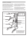
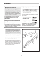
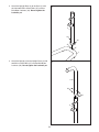
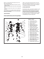
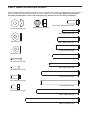
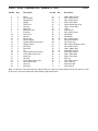
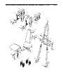
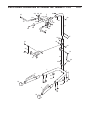
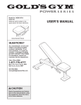
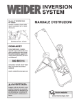
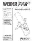
Model No. GGBE1774.0
Serial No.
Write the serial number in the
space above for future reference.
Serial Number Decal
QUESTIONS?
As a manufacturer, we are committed to providing complete
customer satisfaction. If you
have questions, or if a part is
damaged or missing, PLEASE
CONTACT OUR CUSTOMER
SERVICE DEPARTMENT
DIRECTLY.
CALL TOLL-FREE:
1-877-776-4777
Mon.–Fri., 6 a.m.–6 p.m. MST
ON THE WEB:
www.goldsgympowerflex.com
CAUTION
Read all precautions and instructions in this manual before using
this equipment. Save this manual
for future reference.
USER’S MANUAL
TABLE OF CONTENTS
WARNING DECAL PLACEMENT . . . . . . . . . . . . . . . . . . . . . . . . . . . . . . . . . . . . . . . . . . . . . . . . . . . . . . . . . . . . . 2
IMPORTANT PRECAUTIONS . . . . . . . . . . . . . . . . . . . . . . . . . . . . . . . . . . . . . . . . . . . . . . . . . . . . . . . . . . . . . . . . 3
BEFORE YOU BEGIN . . . . . . . . . . . . . . . . . . . . . . . . . . . . . . . . . . . . . . . . . . . . . . . . . . . . . . . . . . . . . . . . . . . . . . 4
ASSEMBLY . . . . . . . . . . . . . . . . . . . . . . . . . . . . . . . . . . . . . . . . . . . . . . . . . . . . . . . . . . . . . . . . . . . . . . . . . . . . . . 5
ADJUSTMENTS . . . . . . . . . . . . . . . . . . . . . . . . . . . . . . . . . . . . . . . . . . . . . . . . . . . . . . . . . . . . . . . . . . . . . . . . . .12
EXERCISE GUIDELINES . . . . . . . . . . . . . . . . . . . . . . . . . . . . . . . . . . . . . . . . . . . . . . . . . . . . . . . . . . . . . . . . . . 14
ORDERING REPLACEMENT PARTS . . . . . . . . . . . . . . . . . . . . . . . . . . . . . . . . . . . . . . . . . . . . . . . . . .Back Cover
LIMITED WARRANTY . . . . . . . . . . . . . . . . . . . . . . . . . . . . . . . . . . . . . . . . . . . . . . . . . . . . . . . . . . . . . . Back Cover
Note: A PART IDENTIFICATION CHART and a PART LIST/EXPLODED DRAWING are attached in the center of
this manual. Remove the PART IDENTIFICATION CHART and PART LIST/EXPLODED DRAWING before beginning assembly.
WARNING DECAL PLACEMENT
The decals shown here have
been placed on the exercise
rack. If a decal is missing or
illegible, please call the tollfree telephone number on the
front cover of this manual and
order a free replacement
decal. Apply the decal in the
location shown.
Keep hands and
fingers clear of
this area.
GOLD'S GYM is a registered trademark of Gold's Gym International, Inc. This product is manufactured and
distributed under license from Gold's Gym International, Inc.
2
IMPORTANT PRECAUTIONS
WARNING:
To reduce the risk of serious injury, read the following important precautions
before using the exercise rack.
1. Read all instructions in this manual and all
warnings on the exercise rack before using
the exercise rack. Use the exercise rack only
as described in this manual.
7. Inspect and properly tighten all parts regular-
ly. Replace any worn parts immediately.
8. Always make sure that the pins and knobs
are fully engaged before the exercise rack is
used.
2. It is the responsibility of the owner to ensure
that all users of the exercise rack are adequately informed of all precautions.
9. Never use the knee pad without at least one
resistance band connecting the support
frame to the pivot arm.
3. The exercise rack is intended for home use
only. Do not use the exercise rack in any
commercial, rental, or institutional setting.
10. Always wear athletic shoes for foot protection while exercising.
4. Keep the exercise rack indoors, away from
moisture and dust. Place the exercise rack on
a level surface, with a mat beneath it to protect the floor or carpet.
11. The exercise rack is designed to support a
maximum user weight of 300 pounds.
12. If you feel pain or dizziness at any time while
exercising, stop immediately and begin cooling down.
5. Make sure that there is enough clearance
around the exercise rack to mount, dismount,
and use the exercise rack.
6. Keep children under 12 and pets away from
the exercise rack at all times.
WARNING:
Before beginning this or any exercise program, consult your physician. This
is especially important for persons over the age of 35 or persons with pre-existing health problems.
Read all instructions before using. ICON assumes no responsibility for personal injury or property
damage sustained by or through the use of this product.
3
BEFORE YOU BEGIN
al. To help us assist you, please note the product
model number and serial number before calling. The
model number is GGBE17740. The serial number can
be found on a decal attached to the exercise rack (see
the front cover of this manual).
Thank you for selecting the versatile GOLD’S GYM®
POWER SERIES GT 2000 exercise rack. The exercise
rack offers a selection of exercise stations designed to
develop every major muscle group of the body.
Whether your goal is to tone your body, build dramatic
muscle size and strength, or improve your cardiovascular system, the exercise rack will help you to
achieve the specific results you want.
To avoid a registration fee for any service needed
under warranty, you must register the exercise rack
at www.goldsgympowerflex.com/registration.
For your benefit, read this manual carefully before
using the exercise rack. If you have questions after
reading this manual, see the front cover of this manu-
Before reading further, please review the drawing below
and familiarize yourself with the parts that are labeled.
ASSEMBLED DIMENSIONS:
Height: 82 in. / 208 cm
Width: 42 in. / 107 cm
Depth: 48 in. / 122 cm
Pull-up Handle
Arm Pad
Backrest
Dip Arm
Adjustment Pin
Right Side
Adjustment Pin
Resistance Band
Knee Pad
Left Side
Push-up Handle
Note: The terms “right side” and “left
side” are determined relative to a person with their back to the backrest;
they do not correspond to right and
left on the drawings in the manual.
4
ASSEMBLY
• Tighten all parts as you assemble them, unless
instructed to do otherwise.
Make Things Easier for Yourself
Everything in this manual is designed to ensure
that the exercise rack can be assembled successfully by anyone. However, it is important to
realize that the versatile exercise rack has many
parts and that the assembly process will take
time. Most people find that by setting aside plenty of time, assembly will go smoothly.
• As you assemble the exercise rack, make sure all
parts are oriented as shown in the drawings.
• For help identifying small parts, use the PART
IDENTIFICATION CHART.
The following tools (not included) are required
for assembly:
To hire an authorized service technician to
assemble the weight bench, call toll-free
1-800-445-2480.
• Two adjustable wrenches
Before beginning assembly, carefully read the
following information and instructions:
• One standard screwdriver
• One rubber mallet
• One Phillips screwdriver
• Assembly requires two people.
Assembly will be more convenient if you have a
socket set, a set of open-end or closed-end
wrenches, or a set of ratchet wrenches.
• Place all parts in a cleared area and remove the
packing materials. Do not dispose of the packing
materials until assembly is completed.
1.
1
Before beginning assembly, make sure that
you have read and understand the information in the box above. Refer to the PART
IDENTIFICATION CHART for help identifying
small parts.
47
46
1
17
Attach two Base Pads (17) to the Base (1) with
two M4 x 20mm Screws (42).
42
Press a Base Cap (16) onto a Base Handle (2).
Repeat with the other Base Handle.
17
2
42
Insert the two Base Handles (2) into the Base (1)
as shown. Insert four M10 x 90mm Bolts (46) and
two M10 x 87mm Bolts (47) up through the Base.
It may be helpful to place tape over the bolt
heads to hold them in place.
46
2
16
5
2. Attach the Upright Base (3) to the Base (1) with
the indicated M10 x 87mm Bolts (47) and two
M10 Nylon Locknuts (44). Do not tighten the
Locknuts yet.
2
3
44
44
47
47
1
3. Attach the Upright (4) to the Upright Base (3) with
two M10 x 87mm Bolts (47) and two M10 Nylon
Locknuts (44). Do not tighten the Locknuts yet.
3
4
44
47
3
6
4. Attach the Left Leg (6) to the Base (1) with the
indicated M10 x 90mm Bolts (46) and two M10
Nylon Locknuts (44). Do not tighten the
Locknuts yet.
4
Repeat this step with the Right Leg (7).
7
6
44
44
1
46
5. Slide the Backrest Frame (8) onto the Left and
Right Legs (6, 7) and over the Upright (4) as
shown.
5
32
Attach the Top Frame (5) inside the Upright (4)
with two M8 x 15mm Screws (28). Do not tighten the Screws yet.
8
28
Attach the Backrest Frame (8) and the Top Frame
(5) to the Upright (4) with an M10 x 127mm Bolt
(32) and an M10 Nylon Locknut (44). Do not
tighten the Locknut yet.
4
5
28
44
Attach the Top Frame Cap (40) to the Top Frame
(5) with an M4 x 25mm Screw (45).
45
40
7
6
7
6. Attach the Support Frame (15) to the Upright
Base (3) with an M10 x 62mm Bolt (24) and an
M10 Nylon Locknut (44). Do not tighten the
Locknuts yet.
6
8
Attach the Support Frame (15) and the Left and
Right Legs (6, 7) to the Backrest Frame (8) with
four M10 x 53mm Bolts (30) and four M10 Nylon
Locknuts (44).
30
44
44
Tighten the M10 Nylon Locknuts (44) and M8 x
15mm Screws (49) used in steps 2–6.
24
15
30
44
7. Attach a Pull-up Handle (13) inside the Top
Frame (5) with four M8 x 19mm Screws (38) and
four M8 Curved Washers (39).
3
6
7
7
Slide a 51mm Round Outer Cap (23) onto the
Pull-up Handle (13) and press the Cap into the
Top Frame (5).
38
Repeat this step on the other side of the Top
Frame (5).
39
38
23
38
13
8. Attach the Pad Frame (10) to the Pivot Arm (9)
with two M8 x 19mm Screws (38), two M8
Washers (37), and two 5mm Spacers (34).
5
38
39
8
38
9
34
37
37
34
10
8
38
9. Attach the Knee Pad (21) to Pad Frame (10) with
two M6 x 70mm Screws (35) and two M6
Washers (36).
9
21
10
36
36
35
35
10. Attach the Pivot Arm (9) to the Upright Base (3)
with the Pin (18). Make sure the Pin is inserted
all the way through the Upright Base and
Pivot Arm.
10
3
9
11. Slide two 15-pound Resistance Bands (19) onto
the indicated tubes on the Support Frame (15)
and Pivot Arm (9).
11
Attach the Cable (33) to the Support Frame (15)
and Pivot Arm (9) with two M8 x 25mm Shoulder
Screws (41). Make sure that the cable ends
pivot freely on the Bolts.
18
41
33
41
15
19
19
9
9
12. Hold the Dip Arm (11) behind the Backrest Frame
(8) as shown. Attach the Dip Arm to the Backrest
Frame with two M10 x 100mm Bolts (43) and two
M10 Nylon Locknuts (44). Do not overtighten
the Locknuts; the Dip Arm must be able to
pivot easily.
12
11
43
44
8
43
13. Attach the Right Pad Base (26) and an Arm Pad
(25) to the Dip Arm (11) with two M6 x 70mm
Screws (35) and two M6 Washers (36).
13
25
Repeat this step on the other side of the Dip
Arm (11).
11
26
36
36
35
14. Attach a Dip Handle (12) to the Dip Arm (11) with
an M10 x 50mm Screw (27) and a Dip Cap (48).
14
Repeat this step on the other side of the Dip
Arm (11).
11
48
27
12
10
15. Attach a Pin (18) to the Backrest Frame (8) with
an M4 x 25mm Screw (45).
15
8
Insert the Pin (18) into the Backrest Frame (8).
18
45
16. Attach the Backrest (22) to the Backrest Frame
(8) with an M6 x 38mm Screw (29) and an M6
Washer (36).
16
36
8
Attach the Backrest (22) to the Support Frame
(15) with two M6 x 70mm Screws (35) and two
M6 Washers (36).
29
36
15
35
36
22
35
17. Make sure that all parts have been properly
tightened before the exercise rack is used.
11
ADJUSTMENTS
This section explains how to adjust the exercise rack. See the EXERCISE GUIDELINES on page 14 for important information about how to get the most benefit from your exercise program. Also, refer to the accompanying
exercise guide to see the correct form for each exercise.
Make sure all parts are properly tightened each time the exercise rack is used. Replace any worn parts immediately. The exercise rack can be cleaned with a damp cloth and a mild, non-abrasive detergent. Do not use solvents.
ADJUSTING THE DIP ARM
To perform some exercises, the Dip Arm (11) should
be locked in the up position. Remove the indicated
Pin (18) and lift the Dip Handle (12). Engage the Pin
into the Backrest Frame (8) and the hole in the Dip
Arm plate.
11
To use the Dip Arm (11), remove the Pin (18) and
lower the Dip Handle (12). Insert the Pin into the
Backrest Frame (8).
18
8
12
ADJUSTING THE KNEE PAD
To change the pivot angle of the knee pad, first make
sure that there are at least two resistance bands
assembled on the Pivot Arm (9) (see USING RESISTANCE BANDS on page 13). Next, hold the Pivot
Arm in the indicated location and remove the indicated Pin (18). Then, align the hole in the Pivot Arm with
the desired hole in the Upright Base (3). Note: The
upper hole will be better for a taller person and
the lower hole will be better for a shorter person.
Find the position that is most comfortable for
you. Finally, reengage the Pin into the Upright Base
and Pivot Arm.
18
3
9
Hold
Here
ADJUSTING THE KNEE PAD
Notch 9
To adjust the Knee Pad (21) to the up position, lift on
the Knee Pad so that the rod on the Pivot Arm (9) is
in the notch in the Pad Frame (10). Then, lower the
Knee Pad so that the 5mm Spacers (34) are in the
top of the “L”-slot in the Pad Frame (10).
“L”-slot
21
10
To adjust the Knee Pad (21) to the down position, lift
on the Knee Pad and slide the Pad Frame forward,
disengaging the rod on the Pivot Arm (9). Lower the
Knee Pad.
34
12
Rod
USING THE RESISTANCE BANDS
To add resistance to the Pivot Arm (9), slide a
Resistance Band (19 or 14) onto the tubes on the
Pivot Arm and the Support Frame (15).
Store Resistance Bands (19 or 14) on the storage
tube when they are not being used.
15
Storage
Tube
WARNING:
Never use the Knee
Pad (21) without at least one Resistance Band
(19 or 14) connecting the Support Frame (15) to
the Pivot Arm (9).
9
14
21
13
19
EXERCISE GUIDELINES
THE FOUR BASIC TYPES OF WORKOUTS
PERSONALIZING YOUR EXERCISE PROGRAM
Muscle Building
To increase the size and strength of your muscles,
push them close to their maximum capacity. Your muscles will adapt and grow as you progressively increase
the intensity of your exercise. You can adjust the intensity level of an individual exercise in two ways:
• by changing the amount of resistance used
• by changing the number of repetitions or sets performed. (A “repetition” is one complete cycle of an
exercise, such as one sit-up. A “set” is a series of
repetitions.)
Determining the exact length of time for each workout,
as well as the number of repetitions or sets completed,
is an individual matter. It is important to avoid overdoing it during the first few months of your exercise program. You should progress at your own pace and be
sensitive to your body’s signals. If you experience pain
or dizziness at any time while exercising, stop immediately and begin cooling down. Find out what is wrong
before continuing. Remember that adequate rest and a
proper diet are important factors in any exercise program.
The proper amount of resistance for each exercise
depends upon the individual user. You must gauge
your limits and select the amount of resistance that is
right for you. Begin with 3 sets of 8 repetitions for each
exercise you perform. Rest for 3 minutes after each
set. When you can complete 3 sets of 12 repetitions
without difficulty, increase the amount of resistance.
WARMING UP
Toning
You can tone your muscles by pushing them to a moderate percentage of their capacity. Select a moderate
amount of resistance and increase the number of repetitions in each set. Complete as many sets of 15 to
20 repetitions as possible without discomfort. Rest for
1 minute after each set. Work your muscles by completing more sets rather than by using high amounts of
resistance.
WORKING OUT
Begin each workout with 5 to 10 minutes of stretching
and light exercise to warm up. Warming up prepares
your body for more strenuous exercise by increasing
circulation, raising your body temperature and delivering more oxygen to your muscles.
Each workout should include 6 to 10 different exercises. Select exercises for every major muscle group,
emphasizing areas that you want to develop most. To
give balance and variety to your workouts, vary the
exercises from session to session.
Schedule your workouts for the time of day when your
energy level is the highest. Each workout should be
followed by at least one day of rest. Once you find the
schedule that is right for you, stick with it.
Weight Loss
To lose weight, use a low amount of resistance and
increase the number of repetitions in each set.
Exercise for 20 to 30 minutes, resting for a maximum
of 30 seconds between sets.
EXERCISE FORM
Cross Training
Cross training is an efficient way to get a complete and
well-balanced fitness program. An example of a balanced program is:
• Plan strength training workouts on Monday,
Wednesday, and Friday.
• Plan 20 to 30 minutes of aerobic exercise, such as
running on a treadmill or riding on an elliptical or
exercise bike, on Tuesday and Thursday.
• Rest from both strength training and aerobic exercise
for at least one full day each week to give your body
time to regenerate.
The combination of strength training and aerobic exercise will reshape and strengthen your body, plus develop your heart and lungs.
Maintaining proper form is an essential part of an
effective exercise program. This requires moving
through the full range of motion for each exercise, and
moving only the appropriate parts of the body.
Exercising in an uncontrolled manner will leave you
feeling exhausted. On the exercise guide accompanying this manual you will find photographs showing the
correct form for several exercises, and a list of the
muscles affected. Refer to the muscle chart on the
next page to find the names of the muscles.
The repetitions in each set should be performed
smoothly and without pausing. The exertion stage of
each repetition should last about half as long as the
return stage. Proper breathing is important. Exhale
during the exertion stage of each repetition and inhale
during the return stroke. Never hold your breath.
14
slowly as you stretch and do not bounce. Ease into
each stretch gradually and go only as far as you can
without strain. Stretching at the end of each workout
is an effective way to increase flexibility.
Rest for a short period of time after each set. The
ideal resting periods are:
• Rest for three minutes after each set for a muscle
building workout.
• Rest for one minute after each set for a toning workout.
• Rest for 30 seconds after each set for a weight loss
workout.
Plan to spend the first couple of weeks familiarizing
yourself with the equipment and learning the proper
form for each exercise.
STAYING MOTIVATED
For motivation, keep a record of each workout. List the
date, the exercises performed, the resistance used,
and the numbers of sets and repetitions completed.
Record your weight and key body measurements at
the end of every month. Remember, the key to achieving the greatest results is to make exercise a regular
and enjoyable part of your everyday life.
COOLING DOWN
End each workout with 5 to 10 minutes of stretching.
Include stretches for both your arms and legs. Move
MUSCLE CHART
O
A
P
L
B
Q
C
R
D
S
E
T
F
G
M
U
N
H
V
I
W
J
X
K
15
A.
B.
C.
D.
E.
F.
G.
H.
I.
J.
K.
L.
M.
N.
O.
P.
Q.
R.
S.
T.
U.
V.
W.
X.
Sternomastoid (neck)
Pectoralis Major (chest)
Biceps (front of arm)
Obliques (waist)
Brachioradials (forearm)
Hip Flexors (upper thigh)
Abductor (outer thigh)
Quadriceps (front of thigh)
Sartorius (front of thigh)
Tibialis Anterior (front of calf)
Soleus (front of calf)
Anterior Deltoid (shoulder)
Rectus Abdominus (stomach)
Adductor (inner thigh)
Trapezius (upper back)
Rhomboideus (upper back)
Posterior Deltoid (shoulder)
Triceps (back of arm)
Latissimus Dorsi (mid back)
Spinae Erectors (lower back)
Gluteus Medius (hip)
Gluteus Maximus (buttocks)
Hamstring (back of leg)
Gastrocnemius (back of calf)
PART IDENTIFICATION CHART
See the drawings below to identify small parts used in assembly. The number in parentheses by each drawing is
the key number of the part, from the PART LIST in the center of this manual. Note: Some small parts may
have been pre-attached. If a part is not in the parts bag, check to see if it has been pre-attached.
M8 x 25mm Shoulder Screw (41)
M8 Curve Washer (39)
M10 Nylon Locknut (44)
M6 x 38mm Screw (29)
M8 Washer (37)
M10 x 50mm Screw (27)
M10 x 53mm Bolt (30)
M6 Washer (36)
M10 x 62mm Bolt (24)
M4 x 25mm Screw (45)
M6 x 70mm Screw (35)
M4 x 20mm Screw (42)
M10 x 87mm Bolt (47)
M8 x 19mm Screw (38)
M10 x 90mm Bolt (46)
M8 x 15mm Screw (28)
M10 x 100mm Bolt (43)
M10 x 127mm Bolt (32)
PART LIST—Model No. GGBE1774.0
Key No.
Qty.
1
2
3
4
5
6
7
8
9
10
11
12
13
14
15
16
17
18
19
20
21
22
23
24
25
26
1
2
1
1
1
1
1
1
1
1
1
2
2
2
1
2
2
2
2
1
1
1
2
1
2
2
Description
Base
Base Handle
Upright Base
Upright
Top Frame
Left Leg
Right Leg
Backrest Frame
Pivot Arm
Pad Frame
Dip Arm
Dip Handle
Pull-up Handle
25-pound Resistance Band
Support Frame
Base Cap
Base Pad
Pin
15-pound Resistance Band
51mm Round Inner Cap
Knee Pad
Backrest
51mm Round Outer Cap
M10 x 62mm Bolt
Arm Pad
Pad Base
Key No. Qty.
27
28
29
30
31
32
33
34
35
36
37
38
39
40
41
42
43
44
45
46
47
48
49
#
#
#
2
2
1
4
6
1
1
2
8
9
2
10
8
1
2
2
2
16
2
4
4
2
1
1
1
2
R0505A
Description
M10 x 50mm Screw
M8 x 15mm Screw
M6 x 38mm Screw
M10 x 53mm Bolt
29mm Round Inner Cap
M10 x 127mm Bolt
Cable
5mm Spacer
M6 x 70mm Screw
M6 Washer
M8 Washer
M8 x 19mm Screw
M8 Curved Washer
Top Frame Cap
M8 x 25mm Shoulder Screw
M4 x 20mm Screw
M10 x 100mm Bolt
M10 Nylon Locknut
M4 x 25mm Screw
M10 x 90mm Bolt
M10 x 87mm Bolt
Dip Cap
M4 x 10mm Screw
User’s Manual
Exercise Guide
Allen Wrench
Note: “#” indicates a non-illustrated part. Specifications are subject to change without notice. See the back cover
of the user’s manual for information about ordering replacement parts.
EXPLODED DRAWING A—Model No. GGBE1774.0
R0505A
25
31
27
11
26
25
26
31
48
36
32
35
12
31
36
48
8
35
27
12
31
36
29
43
36
35
36
30
43
44
18
22
38
37
21
44
9
30
34
45
34
37
10
7
38
6
36
20
36
35
19
35
44
44
14
44
44
EXPLODED DRAWING B—Model No. GGBE1774.0
38
31
39 38
28
5
23
28
38
13
38
39
44
38
38
38
39
40
23
45
4
39
38
31
13
47
44
44
41
24
33
18
41
3
15
49
44
44
1
2
17
42
16
17
46
42
2
46
16
47
R0505A
ORDERING REPLACEMENT PARTS
To order replacement parts, see the front cover of this manual. To help us assist you, please be prepared to give
the following information:
1. the MODEL NUMBER of the product (GGBE1774.0)
2. the NAME of the product (GOLD’S GYM POWER SERIES GT 2000 exercise rack)
3. the SERIAL NUMBER of the product (see the front cover of this manual)
4. the KEY NUMBER and DESCRIPTION of the part(s) (see the PART LIST and EXPLODED DRAWING at the
center of this manual)
LIMITED WARRANTY
ICON Health & Fitness, Inc. (ICON), warrants this product to be free from defects in workmanship and
material, under normal use and service conditions, for a period of ninety (90) days from the date of purchase. This warranty extends only to the original purchaser. ICON's obligation under this warranty is limited to replacing or repairing, at ICON's option, the product through one of its authorized service centers.
All repairs for which warranty claims are made must be pre-authorized by ICON. If the product is shipped
to a service center, freight charges to and from the service center will be the customer’s responsibility. For
in-home service, the customer will be responsible for a minimal trip charge. This warranty does not extend
to any product or damage to a product caused by or attributable to freight damage, abuse, misuse,
improper or abnormal usage or repairs not provided by an ICON authorized service center; products used
for commercial or rental purposes; or products used as store display models. No other warranty beyond
that specifically set forth above is authorized by ICON.
ICON is not responsible or liable for indirect, special or consequential damages arising out of or in connection with the use or performance of the product or damages with respect to any economic loss, loss
of property, loss of revenues or profits, loss of enjoyment or use, costs of removal or installation or other
consequential damages of whatsoever nature. Some states do not allow the exclusion or limitation of incidental or consequential damages. Accordingly, the above limitation may not apply to you.
The warranty extended hereunder is in lieu of any and all other warranties and any implied warranties of
merchantability or fitness for a particular purpose is limited in its scope and duration to the terms set forth
herein. Some states do not allow limitations on how long an implied warranty lasts. Accordingly, the above
limitation may not apply to you.
This warranty gives you specific legal rights. You may also have other rights which vary from state to state.
ICON HEALTH & FITNESS, INC., 1500 S. 1000 W., LOGAN, UT 84321-9813
Part No. 222426 R0505A
Printed in China © 2004 ICON IP, Inc.