1
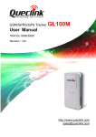
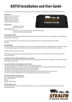
TR-606B Installation Guide
Cable description
14 Pin I/O Cable
Wire Color
Green/ White
White
Gray
Purple
Blue
Black
Red
Description
Analog Input_1
Digital Output 3 (Negative Trigger)
Digital Output 1 (Negative Trigger)
Digital Input 3 (Positive Trigger)
Digital Input 1 (Negative Trigger)
Ground
Main Power
Green
Yellow
Orange
Brown
Pink
Black
Digital Output 2 (Negative Trigger)
ACC (Positive Trigger)
Digital Input 2 (Negative Trigger)
SOS (Negative Trigger)
12V/24V Backup Battery
Ground
Connecting the Main Power
Connect the red wire from the cable to a power source of 10~36 V. Connect the black
wire to ground.
Note: Please make sure the external power is well connected to TR-606B.
Connecting ignition detection line on car/asset
Ignition On
ACC
Off
Lock
Connect the yellow wire from the cable to ACC/Ignition (12V) position of
vehicle/asset. Connect the black wire to ground.
Connecting the GSM & GPS Antennas:
The TR-606 does not have any internal GPS or GSM antennas, so the external
antennas for GPS and GSM must be connected in order for the TR-606 to work.
Connect GSM antenna
Connect GPS antenna
Installation Notice of TR-606:
Notice:
The GPS signal and GSM signal would be significantly reduced
or fully blocked by the metal shielding material. In order to have
the device work properly, please avoid installing in metal
shielding environments. E.g. sealed metal box.
Notice:
GPS device must be placed under open sky condition to
achieve the best performance. Indoor installation will severely
degrade the signal and result in location fixing failure.
Notice:
Please use TR-606B in the area with stable GPRS/UMTS
coverage area.
Recommended Installation Position:
In order to advance the sensitivity of motion sensor, please install the TR-600
Device horizontally.
Vertically install of the device would decrease the sensitivity of motion sensor and might fail to
trigger the motion reports.