1
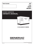
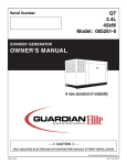
1.6L 25kW Models: 005324-0 005325-0 Serial Number STANDBY GENERATOR OWNER'S MANUAL A new standard of reliability Not intended for use in critical life support applications. —CAUTION— ONLY QUALIFIED ELECTRICIANS OR CONTRACTORS SHOULD ATTEMPT INSTALLATION! DEADLY EXHAUST FUMES. OUTDOOR INSTALLATION ONLY! This manual should remain with the unit. Cover053 Rev. A 05/06 Part No. 0G1260 Standby Generator Sets Table of Contents INTRODUCTION .....................................................1-3 Read this Manual Thoroughly ...................................1-3 Operation and Maintenance ......................................1-3 How to Obtain Service ..............................................1-3 IDENTIFICATION RECORD .....................................2-1 Data Label ................................................................2-1 EQUIPMENT DESCRIPTION ...................................3-1 Equipment Description ................................................3-1 Engine Oil Recommendations ......................................3-1 Coolant Recommendations...........................................3-1 ENGINE PROTECTIVE DEVICES ............................4-1 High Coolant Temperature Switch ............................4-1 Low Coolant Level Sensor.........................................4-1 Low Oil Pressure Switch ...........................................4-1 Overcrank Shutdown ................................................4-1 Overspeed Shutdown ................................................4-1 RPM Sensor Loss Shutdown.....................................4-1 DC Fuse ....................................................................4-1 FUEL SYSTEMS .....................................................5-1 Fuel Requirements ....................................................5-1 Natural Gas Fuel System ..........................................5-1 Propane Vapor Withdrawal Fuel System....................5-1 LP Fuel System .........................................................5-1 SPECIFICATIONS ...................................................6-1 Generator .................................................................6-1 Engine.......................................................................6-1 Cooling System .........................................................6-1 Fuel System ..............................................................6-1 Electrical System ......................................................6-1 Cold Weather Kit .......................................................6-2 Reconfiguring the Fuel System ..................................6-2 GENERAL INFORMATION.......................................7-1 Generator AC Lead Connections ..................................7-1 Four-lead, Single-phase Stator ..................................7-1 Alternator Power Winding Connections ........................7-1 3-phase Alternators ..................................................7-1 INSTALLATION.......................................................8-1 Installation ...................................................................8-1 Preparation Before Start-up .........................................8-1 Transfer Switch ........................................................8-1 Fuel System ..............................................................8-1 Generator Set Lubrication ........................................8-1 Prior to Initial Start-up .............................................8-1 Engine Coolant .........................................................8-1 Belt Tension ..............................................................8-1 Electrical System ......................................................8-1 Initial Inspection for QT Genset Start-up .....................8-1 Start-up Checklist ........................................................8-2 Preparation for Start-up............................................8-2 Start-up Inspection ...................................................8-2 OPERATION ...........................................................9-1 Generator Control and Operation ................................9-1 Operating Unit with Manual Transfer Switch ...............9-1 Engine Start-up and Transfer ...................................9-1 Retransfer and Shutdown .........................................9-1 Operating Unit with Automatic Transfer Switch ...........9-1 MAINTENANCE.....................................................10-1 Maintenance Performed by Authorized Service Facilities .....................................................10-1 Every Three Months ...............................................10-1 Once Every Six Months ...........................................10-1 Once Annually.........................................................10-1 First 100 Operating Hours ......................................10-1 Every 500 Operating Hours ....................................10-1 Every 800 Operating Hours ....................................10-1 Exhaust Manifold Procedure ......................................10-1 Intake Manifold Procedure .........................................10-1 Cylinder Head Procedure ...........................................10-1 Cooling System ..........................................................10-2 Overload Protection for Engine DC Electrical System ....................................................10-2 Checking Fluid Levels ................................................10-2 Check Engine Oil ....................................................10-2 Battery Fluid ...........................................................10-2 Engine Coolant .......................................................10-2 Maintenance Owner/Operator Can Perform ................10-3 Check Engine Oil Level ...........................................10-3 Check Battery .........................................................10-3 Exercise System ......................................................10-3 Inspect Cooling System ...........................................10-3 Check Engine Coolant Level....................................10-3 Perform Visual Inspection .......................................10-3 Inspect Exhaust System ..........................................10-3 Check Fan Belt........................................................10-3 Inspect Engine Governor ........................................10-3 Changing Engine Oil ...............................................10-3 Changing the Engine Air Cleaner ............................10-3 Spark Plugs ............................................................10-4 Coolant Change .......................................................10-4 Miscellaneous Maintenance ........................................10-4 Cleaning the Generator ...........................................10-4 Battery ....................................................................10-4 Battery Maintenance ...............................................10-4 Battery Replacement ...............................................10-5 SERVICE SCHEDULE ...........................................11-1 TROUBLESHOOTING ...........................................12-1 Troubleshooting Guide...............................................12-1 NOTES EXPLODED VIEWS & PARTS LISTS WIRING DIAGRAMS & SCHEMATICS WARRANTY Content004 Rev. 0 09/05 SECTION PAGE SAFETY RULES ................................................ 1-1 Standby Generator Sets Important Safety Instructions WARNING: GENERAL HAZARDS • For safety reasons, the manufacturer recommends that this equipment be installed, serviced and repaired by an Authorized Service Dealer or other competent, qualified electrician or installation technician who is familiar with applicable codes, standards and regulations. The operator also must comply with all such codes, standards and regulations. • Installation, operation, servicing and repair of this (and related) equipment must always comply with applicable codes, standards, laws and regulations. Adhere strictly to local, state and national electrical and building codes. Comply with regulations the Occupational Safety and Health Administration (OSHA) has established. Also, ensure that the generator is installed, operated and serviced in accordance with the manufacturer’s instructions and recommendations. Following installation, do nothing that might render the unit unsafe or in noncompliance with the aforementioned codes, standards, laws and regulations. • The engine exhaust fumes contain carbon monoxide gas, which can be DEADLY. This dangerous gas, if breathed in sufficient concentrations, can cause unconsciousness or even death. For that reason, adequate ventilation must be provided. Exhaust gases must be piped safely away from any building or enclosure that houses the generator to an area where people, animals, etc., will not be harmed. This exhaust system must be installed properly, in strict compliance with applicable codes and standards. • Keep hands, feet, clothing, etc., away from drive belts, fans, and other moving or hot parts. Never remove any drive belt or fan guard while the unit is operating. • Adequate, unobstructed flow of cooling and ventilating air is critical in any room or building housing the generator to prevent buildup of explosive gases and to ensure correct generator operation. Do not alter the installation or permit even partial blockage of ventilation provisions, as this can seriously affect safe operation of the generator. • Keep the area around the generator clean and uncluttered. Remove any materials that could become hazardous. • When working on this equipment, remain alert at all times. Never work on the equipment when physically or mentally fatigued. • Inspect the generator regularly, and promptly repair or replace all worn, damaged or defective parts using only factory-approved parts. The engine exhaust from this product contains chemicals known to the state of California to cause cancer, birth defects or other reproductive harm. WARNING: This product contains or emits chemicals known to the state of California to cause cancer, birth defects or other reproductive harm. Study these SAFETY RULES carefully before installing, operating or servicing this equipment. Become familiar with this Owner’s Manual and with the unit. The generator can operate safely, efficiently and reliably only if it is properly installed, operated and maintained. Many accidents are caused by failing to follow simple and fundamental rules or precautions. The manufacturer cannot anticipate every possible circumstance that might involve a hazard. The warnings in this manual, and on tags and decals affixed to the unit are, therefore, not all inclusive. If a procedure, work method or operating technique is used that the manufacturer does not specifically recommend, ensure that it is safe for others. Also make sure the procedure, work method or operating technique utilized does not render the generator unsafe. DANGER the safe design of this generator, Despite operating this equipment imprudently, neglecting its maintenance or being careless can cause possible injury or death. Permit only responsible and capable persons to install, operate or maintain this equipment. lethal voltages are generated by Potentially these machines. Ensure all steps are taken to render the machine safe before attempting to work on the generator. of the generator are rotating and/or hot Parts during operation. Exercise care near running generators. 1-1 Safety 001 Rev. 0 08/05 SAVE THESE INSTRUCTIONS – The manufacturer suggests that these rules for safe operation be copied and posted in potential hazard areas. Safety should be stressed to all operators, potential operators, and service and repair technicians for this equipment. Standby Generator Sets Important Safety Instructions • Generators installed with an automatic transfer switch will crank and start automatically when normal (utility) source voltage is removed or is below an acceptable preset level. To prevent such automatic start-up and possible injury to personnel, disable the generator’s automatic start circuit (battery cables, etc.) before working on or around the unit. Then, place a “Do Not Operate” tag on the generator control panel and on the transfer switch. • In case of accident caused by electric shock, immediately shut down the source of electrical power. If this is not possible, attempt to free the victim from the live conductor. AVOID DIRECT CONTACT WITH THE VICTIM. Use a nonconducting implement, such as a dry rope or board, to free the victim from the live conductor. If the victim is unconscious, apply first aid and get immediate medical help. • Never wear jewelry when working on this equipment. Jewelry can conduct electricity resulting in electric shock, or may get caught in moving components causing injury. • Before performing any maintenance on the generator, disconnect its battery cables to prevent accidental start-up. Disconnect the cable from the battery post indicated by a NEGATIVE, NEG or (–) first. Reconnect that cable last. • Never use the generator or any of its parts as a step. Stepping on the unit can stress and break parts, and may result in dangerous operating conditions from leaking exhaust gases, fuel leakage, oil leakage, etc. ELECTRICAL HAZARDS • All generators covered by this manual produce dangerous electrical voltages and can cause fatal electrical shock. Utility power delivers extremely high and dangerous voltages to the transfer switch as well as the standby generator. Avoid contact with bare wires, terminals, connections, etc., on the generator as well as the transfer switch, if applicable. Ensure all appropriate covers, guards and barriers are in place before operating the generator. If work must be done around an operating unit, stand on an insulated, dry surface to reduce shock hazard. • Do not handle any kind of electrical device while standing in water, while barefoot, or while hands or feet are wet. DANGEROUS ELECTRICAL SHOCK MAY RESULT. • If personnel must stand on metal or concrete while installing, operating, servicing, adjusting or repairing this equipment, place insulative mats over a dry wooden platform. Work on the equipment only while standing on such insulative mats. • The National Electrical Code (NEC) requires the frame and external electrically conductive parts of the generator to be connected to an approved earth ground. This grounding will help prevent dangerous electrical shock that might be caused by a ground fault condition in the generator set or by static electricity. Never disconnect the ground wire. • Wire gauge sizes of electrical wiring, cables and cord sets must be adequate to handle the maximum electrical current (ampacity) to which they will be subjected. • Before installing or servicing this (and related) equipment, make sure that all power voltage supplies are positively turned off at their source. Failure to do so will result in hazardous and possibly fatal electrical shock. • Connecting this unit to an electrical system normally supplied by an electric utility shall be by means of a transfer switch so as to isolate the generator electric system from the electric utility distribution system when the generator is operating. Failure to isolate the two electric system power sources from each other by such means will result in damage to the generator and may also result in injury or death to utility power workers due to backfeed of electrical energy. FIRE HAZARDS • Keep a fire extinguisher near the generator at all times. Do NOT use any carbon tetra-chloride type extinguisher. Its fumes are toxic, and the liquid can deteriorate wiring insulation. Keep the extinguisher properly charged and be familiar with its use. If there are any questions pertaining to fire extinguishers, consult the local fire department. EXPLOSION HAZARDS • Properly ventilate any room or building housing the generator to prevent build-up of explosive gas. • Do not smoke around the generator. Wipe up any fuel or oil spills immediately. Ensure that no combustible materials are left in the generator compartment, or on or near the generator, as FIRE or EXPLOSION may result. Keep the area surrounding the generator clean and free from debris. • These generator sets may operate using one of several types of fuels. All fuel types are potentially FLAMMABLE and/or EXPLOSIVE and should be handled with care. Comply with all laws regulating the storage and handling of fuels. Inspect the unit’s fuel system frequently and correct any leaks immediately. Fuel supply lines must be properly installed, purged and leak tested according to applicable fuel-gas codes before placing this equipment into service. • Diesel fuels are highly FLAMMABLE. Gaseous fluids such as natural gas and liquid propane (LP) gas are extremely EXPLOSIVE. Natural gas is lighter than air, and LP gas is heavier than air; install leak detectors accordingly. 1-2 Safety 001 Rev. 0 08/05 Standby Generator Sets Important Safety Instructions INTRODUCTION This symbol points out potential fire hazard. symbol points out potential electrical shock This hazard. Thank you for purchasing this model of the standby generator set product line. Every effort was expended to make sure that the information and instructions in this manual were both accurate and current at the time the manual was written. However, the manufacturer reserves the right to change, alter or otherwise improve this product(s) at any time without prior notice. The operator is responsible for proper and safe use of the equipment. The manufacturer strongly recommends that the operator read this Owner's Manual and thoroughly understand all instructions before using this equipment. The manufacturer also strongly recommends instructing other users to properly start and operate the unit. This prepares them if they need to operate the equipment in an emergency. READ THIS MANUAL THOROUGHLY If any portion of this manual is not understood, contact the nearest Authorized Service Dealer for starting, operating and servicing procedures. OPERATION AND MAINTENANCE It is the operator's responsibility to perform all safety checks, to make sure that all maintenance for safe operation is performed promptly, and to have the equipment checked periodically by an Authorized Service Dealer. Normal maintenance service and replacement of parts are the responsibility of the owner/operator and, as such, are not considered defects in materials or workmanship within the terms of the warranty. Individual operating habits and usage contribute to the need for maintenance service. Throughout this publication, and on tags and decals affixed to the generator, DANGER, WARNING, CAUTION and NOTE blocks are used to alert personnel to special instructions about a particular service or operation that may be hazardous if performed incorrectly or carelessly. Observe them carefully. Their definitions are as follows: DANGER After this heading, read instructions that, if not strictly complied with, will result in personal injury or property damage. Proper maintenance and care of the generator ensure a minimum number of problems and keep operating expenses at a minimum. See an Authorized Service Dealer for service aids and accessories. Operating instructions presented in this manual assume that the standby electric system has been installed by an Authorized Service Dealer or other competent, qualified contractor. Installation of this equipment is not a “do-it-yourself” project. After this heading, read instructions that, if not strictly complied with, may result in personal injury or property damage. HOW TO OBTAIN SERVICE After this heading, read instructions that, if not strictly complied with, could result in damage to equipment and/or property. NOTE: When the generator requires servicing or repairs, simply contact an Authorized Service Dealer for assistance. Service technicians are factory-trained and are capable of handling all service needs. After this heading, read explanatory statements that require special emphasis. When contacting an Authorized Service Dealer or the factory about parts and service, always supply the complete model number of the unit as given on the front cover of this manual or on the DATA LABEL affixed to the unit. These safety warnings cannot eliminate the hazards that they indicate. Common sense and strict compliance with the special instructions while performing the service are essential to preventing accidents. Four commonly used safety symbols accompany the DANGER, WARNING and CAUTION blocks. The type of information each indicates is as follows: To locate the nearest AUTHORIZED SERVICE DEALER, please call this number: This symbol points out important safety information that, if not followed, could endanger personal safety and/or property of others. 1-800-333-1322 symbol points out potential explosion This hazard. or locate us on the web at: www.generac.com 1-3 Safety 001 Rev. 0 08/05 AUTHORIZED SERVICE DEALER LOCATION Standby Generator Sets General Information IDENTIFICATION RECORD NOTE: For actual information related to this particular model, please refer to the Manual Drawing Listing located at the end of this manual, or to the data label affixed to the unit. DATA LABEL Every generator set has a DATA LABEL that contains important information pertinent to the generator. The data label, which can be found attached to the generator’s lower connection box, lists the unit’s serial number and its rated voltage, amps, wattage capacity, phase, frequency, rpm, power factor, etc. Generator Model and Serial Number This number is the key to numerous engineering and manufacturing details pertaining to your unit. Always supply this number when requesting service, ordering parts or seeking information. Data Label GENERATOR SET DATA MADE IN USA SERIAL MODEL RATED KVA RATED KW RATED AMPS RATED VOLTAGE POWER FACTOR PHASE HERTZ ALT RPM PRODUCTION DATE ENGINE RPM ALTERNATOR SUBTRANSIENT REACTANCE ALTERNATOR TRANSIENT REACTANCE ROTOR STATOR WINDING INSULATION AT 25°C AMBIENT GENERAC POWER SYSTEMS, INC. WAUKESHA, WI 2-1 Identy 002 Rev. A 12/05 CLASS Standby Generator Sets Equipment Description EQUIPMENT DESCRIPTION COOLANT RECOMMENDATIONS This equipment is a revolving field, alternating current generator set. It is powered by a gaseous fueled engine operating at 1800 rpm for 4-pole direct drive units, 3600 rpm for 2-pole direct drive units and 2300 - 3000 rpm for quiet drive gear units. See the Specifications section for exact numbers. The unit comes complete with a sound attenuated enclosure, internally mounted muffler, control console, mainline circuit breaker, battery charger, and protective alarms as explained in the following paragraph. Use a mixture of half low silicate ethylene glycol base anti-freeze and deionized water. Cooling system capacity is listed in the specifications. Use only deionized water and only low silicate anti-freeze. If desired, add a high quality rust inhibitor to the recommended coolant mixture. When adding coolant, always add the recommended 50-50 mixture. not use any chromate base rust inhibitor Do with ethylene glycol base anti-freeze or chro- All AC connections, including the power leads from the alternator, 120 volt battery charger input and control connections to the transfer switch are available in the main connection box. mium hydroxide (“green slime”) forms and will cause overheating. Engines that have been operated with a chromate base rust inhibitor must be chemically cleaned before adding ethylene glycol base anti-freeze. Using any high silicate anti-freeze boosters or additives will also cause overheating. The manufacturer also recommends that any soluble oil inhibitor is NOT used for this equipment. The generator incorporates the following generator features: • Rotor and Stator insulation is Class F rated as defined by NEMA MG1-32.6, NEMA MG1-1.66. The generator is self ventilated and drip-proof constructed. • The voltage waveform deviation, total harmonic content of the AC waveform and telephone influence factor have been evaluated and are acceptable according to NEMA MG1-32. DANGER not remove the radiator pressure cap while Do the engine is hot or serious burns from boiling liquid or steam could result. glycol base antifreeze is poisonous. Ethylene Do not use mouth to siphon coolant from the ENGINE OIL RECOMMENDATIONS The unit has been filled with 15W-40 engine oil at the factory. Use a high-quality detergent oil classified “For Service CC, SD, SE, SF.” Detergent oils keep the engine cleaner and reduce carbon deposits. Use oil having the following SAE viscosity rating, based on the ambient temperature range anticipated before the next oil change: Temperature Above 80° F (27° C) 32° to 80° F (0° to 27° C) Below 32° F (0° C) radiator, recovery bottle or any container. Wash hands thoroughly after handling. Never store used antifreeze in an open container because animals are attracted to the smell and taste of antifreeze even though it is poisonous to them. Oil Grade (Recommended) SAE 30W or 15W-40 SAE 20W-20 or 15W-40 See Note attempt to crank or start the engine before Any it has been properly serviced with the recommended oil may result in an engine failure. NOTE: For temperatures below 32° F, it is strongly recommended to use the optional Cold Weather Start Kit (part number listed in the Specification Section). The oil grade for temperatures below 32° F is 5W30 synthetic oil. Equip002 Rev. 0 08/05 3-1 Standby Generator Sets Engine Protective Devices ENGINE PROTECTIVE DEVICES OVERCRANK SHUTDOWN The standby generator may be required to operate for long periods of time without an operator on hand to monitor such engine conditions as coolant temperature, oil pressure or rpm. For that reason, the engine has several devices designed to protect it against potentially damaging conditions by automatically shutting down the unit when the oil pressure is too low, the coolant temperature is too high, the coolant level is too low, or the engine is running too fast. After a prespecified duration of cranking, this function ends the cranking if the engine has failed to start. The overcrank LED will turn ON. Turn OFF the AUTO/OFF/MANUAL switch, then turn switch back to AUTO to reset the generator control board. NOTE: If the fault is not corrected, the overcrank feature will continue to activate. NOTE: Approximate Crank Cycle Times Engine protective switches and sensors are mentioned here for the reader’s convenience. Also refer to the applicable control panel manual for additional automatic engine shutdown information. • • • • • HIGH COOLANT TEMPERATURE SWITCH This switches contacts close if the temperature should exceed approximately 140° C (284° F), initiating an engine shutdown. The generator will automatically restart and the LED will reset once the temperature has returned to a safe operating level. 15 seconds ON 7 seconds OFF 7 seconds ON 7 seconds OFF Repeat for 45 seconds Approximately 90 seconds total. OVERSPEED SHUTDOWN A speed circuit controls engine cranking, start-up, operation and shutdown. Engine speed signals are delivered to the circuit board whenever the unit is running. Should the engine overspeed above a safe, preset value, the circuit board initiates an automatic engine shutdown. Contact the nearest Authorized Dealer if this failure occurs. LOW COOLANT LEVEL SENSOR Should the engine coolant level drop below the level of the high coolant temperature switch, it is possible for the engine to overheat without automatic shutdown. To prevent such overheating, the engine has a low coolant level sensor. If the level of engine coolant drops below the level of the low coolant level sensor, the engine automatically shuts down. RPM SENSOR LOSS SHUTDOWN If the speed signal to the control panel is lost, engine shutdown will occur. DC FUSE LOW OIL PRESSURE SWITCH This fuse is located inside of the control panel. It protects the panel wiring and components from damaging overload. Always remove this fuse before commencing work on the generator. The unit will not start or crank if the fuse is blown. Replace the fuse with one of the same size, type, and rating. (See the exploded views and parts lists at the end of this manual for replacement part number.) 4-1 EngProt001 Rev. 0 08/05 This switch has normally closed contacts that are held open by engine oil pressure during cranking and operating. Should oil pressure drop below the 8 psi range, switch contacts close, and the engine shuts down. The unit should not be restarted until oil is added, and the AUTO/OFF/MANUAL switch must be turned to OFF and then back to AUTO. Standby Generator Sets Fuel Systems FUEL SYSTEM PROPANE VAPOR WITHDRAWAL FUEL SYSTEM FUEL REQUIREMENTS This type of system utilizes the vapors formed above the liquid fuel in the supply tank. Approximately 10 to 20 percent of the tank capacity is needed for fuel expansion from the liquid to the vapor state. The vapor withdrawal system is generally best suited for smaller engines that require less fuel. The installer should be aware of the following: The standby generator may be equipped with one of the following fuel systems: • Natural gas fuel system • Propane vapor (PV) fuel system The Manual Drawing Listing that is affixed to the unit includes the “Identification Code,” which may be used to identify the type of fuel system installed on the unit. • The natural gas and LP gas systems are similar. However, the natural gas system delivers gas at a pressure of approximately five inches water column to the carburetor. • When ambient temperatures are low and engine fuel consumption is high, the vapor withdrawal system may not function efficiently. • Ambient temperatures around the supply tank must be high enough to sustain adequate vaporization, or the system will not deliver the needed fuel volume. • In addition to the cooling effects of ambient air, the vaporization process itself provides an additional cooling effect. Recommended fuels should have a Btu content of at least 1,000 Btus per cubic foot for natural gas; or at least 2,520 Btus per cubic foot for LP gas. Ask the fuel supplier for the Btu content of the fuel. Required fuel pressure for natural gas is 5 inches to 14 inches water column (0.18 to 0.5 psi); and for liquid propane, 5 inches to 14 inches of water column (0.18 to 0.5 psi). NOTE: Any piping used to connect the generator to the fuel supply should be of adequate size to ensure the fuel pressure NEVER drops below five inches water column for natural gas or 5 inches water column for propane vapor for all load ranges. LP FUEL SYSTEM LP is supplied as a liquid in pressure tanks. It is usually made up of propane, butane, or a mixture of the two gases. Propane tends to vaporize readily even at temperatures as low as -20° F (-29° C). However, butane reverts to its liquid state when temperatures drop below 32° F (0° C). NOTE: It is the responsibility of the installer to make sure that only the correct recommended fuel is supplied to the generator fuel system. Thereafter, the owner/operator must make certain that only the proper fuel is supplied. LP in a liquid withdrawal system must be converted to its gaseous state before it is introduced into the engine carburetor. A vaporizer-converter is generally used to accomplish this. In such a converter, heated engine coolant is ported through the converter to provide the necessary heat for conversion of the fuel from a liquid to a gaseous state. NATURAL GAS FUEL SYSTEM Natural gas is supplied in its vapor state. In most cases, the gas distribution company provides piping from the main gas distribution line to the standby generator site. The following information applies to natural gas fuel systems. • Gas pressure in a building is usually regulated by national, state and local codes. • To reduce gas pressure to a safe level before the gas enters a building, a primary regulator is needed. The natural gas supplier may or may not supply such a regulator. • It is the responsibility of the gas supplier to make sure sufficient gas pressure is available to operate the primary regulator. • Gas pressure at the inlet to the fuel shutoff solenoid should not exceed approximately 14 inches water column (0.5 psi). Optimum pressure at the fuel shutoff solenoid is 11 inches water column (0.4 psi). FuelSys001 Rev. 0 08/05 5-1 Standby Generator Sets Specifications SPECIFICATIONS Engine Lubrication System Type of Oil Pump ...................................................................... Gear Oil Filter .............................................................Full Flow, Cartridge Crankcase Oil Capacity ....................................................4 U.S. qts. GENERATOR Type ............................................................................. Synchronous Rotor Insulation ....................................................................Class F Stator Insulation ...................................................................Class F Total Harmonic Distortion .........................................................< 5% Alternator Output Leads 3-phase ........................................... 4-wire Bearings .........................................................................Sealed Ball Coupling .......................................................................Flexible Disc Load Capacity (Standby Rating) ............................................25kW* * NOTE: Generator rating and performance in accordance with ISO8528-5, BS5514, SAE J1349, COOLING SYSTEM Type .......................................................................................Closed Water Pump.................................................................... Belt Driven Fan Speed ................................................................................ 2550 Fan Diameter .....................................................................15 inches Fan Mode ..............................................................................Pusher Air Flow (inlet air including alternator and combustion air) .......................................................... 1528 ft3/min. Coolant Capacity ...........................................................2.0 U.S. gal. Heat Rejection to Coolant ..........................................117,000 Btu/h Maximum Operating Air Temp. on Radiator ..............60° C (150° F) Maximum Ambient Temperature................................50° C (140° F) ISO3046 and DIN 6271 Standards. KW rating is based on LPG fuel and may derate with natural gas. Excitation System ....................................................................Direct Generator Output Voltage/kW - 60 Hz kW Amp CB Size 120/240V, 1-phase, 1.0 pf 25 104 125 120/208V, 3-phase, 0.8 pf 25 87 100 Generator Locked Rotor KVA Available @ Voltage Dip of 35% Single-phase or 208 3-phase ............................................. 34 KVA FUEL SYSTEM Type of Fuel .........................................Natural Gas, Propane Vapor Carburetor ...................................................................... Down Draft Secondary Fuel Regulator .................................................Standard Fuel Shut-off Solenoid ........................................................Standard Operating Fuel Pressure ...................... 5 in. - 14 in. Water Column ENGINE Make ................................................................................... Generac Model ..................................................................................... In Line Cylinders and Arrangement............................................................ 4 Displacement ....................................................................... 1.6 Liter Bore ...................................................................................... 3.15 in. Stroke ................................................................................... 3.13 in. Compression Ratio .............................................................9.75-to-1 Air Intake System ...............................................Naturally Aspirated Valve Seats................................................................... Replaceable Lifter Type .......................................................................... Hydraulic Fuel Consumption - ft3/hr (Natural Gas/LPV) Exercise 25% 50% 75% 100% Cycle Load Load Load Load 60/24 161/64 253/101 345/138 437/175 ELECTRICAL SYSTEM Battery Charge Alternator ............................................12V, 15 Amp Static Battery Charger ............................................................2 Amp Recommended Battery...................................... Group 26, 525CCA System Voltage .....................................................................12 Volts Engine Parameters Rated Synchronous RPM ..............................................60 Hz, 3600 HP at rated kW ........................................................................45 Hz Voltage Regulator Type .................................................................................. Electronic Sensing........................................................................ Single-phase Regulation ................................................................................± 1% Features ................................................. V/F Adjustable, Adjustable Voltage and Gain LED Indicators Exhaust System Exhaust Flow at Rated Output 60 Hz.................................. 249 cfm Exhaust Temperature at Rated Output ................................ 1015° F Combustion Air Requirements (Natural Gas) Flow at rated power, 60 Hz ................................................... 90 cfm Power Adjustment for Ambient Conditions Temperature Deration 3% for every 10° C above °C ..................................................... 25 1.65% for every 10° above °F .................................................... 77 Altitude Deration 1% for every 100 m above m ................................................... 182 3% for every 1000 ft. above ft. ................................................. 600 Governor Type .................................................................................. Electronic Frequency Regulation ...................................................Isochronous Steady State Regulation........................................................± .25% Adjustments: Speed ............................................................................ Selectable Controller .................................................R-200 GenSpec022 Rev. 0 04/06 6-1 Standby Generator Sets Specifications Figure 1 — Interconnections Utility In Transfer Switch CONTROL PANEL NEUTRAL TO ALTERNATOR Gen N1 N2 23 194 GENERATOR CONNECTION BOX NEUTRAL N1 N2 23 194 4- # 14 GA WIRES TO GENERATOR CONNECTION BOX CIRCUIT BREAKER 183 178 Battery Charger Input Load Out 186 178 TO GENERATOR CONNECTION BOX GROUND 120 Volt + Neutral Grd To Generator Control Panel FRAME RAIL Ground Level Concrete Slab KW 25 25 STUB-UP AREA See Install Dwg for Dimensions COLD WEATHER KIT CIRCUIT BREAKER SIZE VOLTS / AMPS LUG SIZE 240 1 Ø 125 #4 to 1/0 208 3 Ø 100 #4 to 1/0 10. Reverse the procedure to convert back to natural gas. 11. The Dip switch inside the control panel must be in the LP or NG position when switching to different fuels. For cold climates, optional cold weather kit (part number 0F6148) is recommended. The kit includes: • Battery Warmer • 4” Junction Box with hardware • 6 qt. pack 5W-30 synthetic oil (engine) Figure 6.2 — Reconfigure the Fuel System Port 2 Port 1 RECONFIGURING THE FUEL SYSTEM NOTE: PLUG All models are configured for natural gas or LP vapor from the factory. FUEL HOSE FUEL HOSE BRASS HOSE FITTING OUT PORT 1 BRASS HOSE FITTING PLUG OUT PORT 2 HOUSING PORTS HOUSING PORTS To reconfigure the fuel system from NG to LP, follow these steps: 1. Turn the main gas supply off. 2. Remove the carburetor fuel hose from the outlet port (Port 1) of the demand regulator (Figure 6.2). 3. Remove the brass hose fitting from the outlet port (Port 1) of the demand regulator. 4. Remove pipe plug from Port 2. 5. Install brass hose fitting into Port 2. 6. Install pipe plug into Port 1. 7. Connect carburetor gas hose to brass fitting. 8. Tighten all clamps and plugs. 9. Make sure fuel supply is of the proper pressure and type for configuration. NG FUEL SYSTEM LP FUEL SYSTEM NOTE: Port 1 is for NG only and Port 2 is for LP vapor only. No provision for dual fuel has been made. DANGER injury or damage may occur if not con Serious figured properly. Please consult an Authorized Dealer with any questions. 6-2 GenSpec022 Rev. 0 04/06 Standby Generator Sets General Information GENERATOR AC LEAD CONNECTIONS ALTERNATOR POWER WINDING CONNECTIONS See “Voltage Codes”. This generator may be rated at any one of three voltages, either single-phase or three-phase. The electrical wires in the unit’s AC connection (lower) panel should be installed according to the number of leads and the voltage/phase required for the application. If there are any questions regarding lead connection, refer to the wiring diagrams at the back of this manual. 3-PHASE ALTERNATORS The generator is designed to supply 3-phase electrical loads. Electric power is produced in the alternator power windings. These windings were connected at the factory to the main circuit breaker with a “Y” configuration as shown in Figures 7.2 and 7.3. Voltage codes apply to the type of stator assembly installed on a particular generator. The rated voltage between circuit breaker terminals E1-E2, E1-E3 and E2-E3 is either 480V or 208V depending on the model. FOUR-LEAD, SINGLE-PHASE STATOR The rated voltage between each circuit breaker terminal and the neutral point 00 is either 277V or 120V depending on the model. Four-lead generators (see Figure 7.1) are designed to supply electrical loads with voltage code “A” (240V, 1-phase, 60 Hz). Electrical power is produced in the stator power windings. These windings were connected at the factory to the main circuit breaker as shown in Figure 7.1. Figure 7.2 — Stator Power Winding Connections - 3-phase, 277/480V (6 Lead) The rated voltage between each circuit breaker terminal is 240V. The rated voltage between each circuit breaker terminal and the neutral point 00 is 120V. S1 E1 Figure 7.1 — Four-lead, Single-phase Stator INTERNAL CONNECTIONS L-L S6 S4 NEUTRAL S5 E3 S3 S2 E2 L-N Figure 7.3 — Stator Power Winding Connections - 3-phase, 120/208V (6 Lead) E1 S1 S1 S6 S3 E3 L-L S4 S4 S5 00 (NEUTRAL) S2 S6 S5 S3 S2 E2 L-N ACConn001 Rev. 0 08/05 7-1 Standby Generator Sets Installation PRIOR TO INITIAL START-UP INSTALLATION Refer to the separate “Installation Guide QT Product Line” supplied with the unit. to initially starting the generator, it must Prior be properly prepared for use. Any attempt to PREPARATION BEFORE START-UP The instructions in this section assume that the standby generator has been properly installed, serviced, tested, adjusted and otherwise prepared for use by a competent, qualified installation contractor. Be sure to read the “Safety Rules”, as well as all other safety information in this manual, before attempting to operate this (and related) equipment. crank or start the engine before it has been properly serviced with the recommended types and quantities of engine fluids (oil, coolant, fuel, etc.) may result in an engine failure. ENGINE COOLANT Have the engine cooling system properly filled with the recommended coolant mixture. Check the system for leaks and other problems. See “Specifications” and “Coolant” sections. Before starting the generator for the first time, the installer must complete the following procedures. For follow-up maintenance information and/or service intervals, please refer to the “Maintenance” section and the “Service Schedule”. BELT TENSION TRANSFER SWITCH Check-the engine-fan belt tension and condition prior to placing the unit into service and at recommended intervals. Belt tension is correct when a force of approximately 22 pounds (10 kg), applied midway between pulleys, deflects the belt about 3/8- to 5/8inch (10 to 16 mm). If this generator is used to supply power to any electrical system normally powered by an electric utility, the National Electrical Code requires that a transfer switch be installed. The transfer switch prevents electrical backfeed between two different electrical systems. (For additional information, see the applicable transfer switch manual for this unit.) The transfer switch, as well as the generator and other standby components, must be properly located and mounted in strict compliance with applicable codes, standards and regulations. ELECTRICAL SYSTEM Make sure the generator is properly connected to an approved earth ground. Make sure the generator battery is fully charged, properly installed and interconnected, and ready for use. FUEL SYSTEM Check to ensure that there are no loose electrical connections. Restrain any loose wires to keep them clear of any moving generator set components. Make sure the fuel supply system to the generator (a) delivers the correct fuel at the correct pressure and (b) is properly purged and leak tested according to code. No fuel leakage is permitted. See “Specifications” for more information. INITIAL INSPECTION FOR QT GENSET STARTUP GENERATOR SET LUBRICATION Inspect for the following. • • • • • NOTE: This engine is shipped from the manufacturer with “break-in” oil. This oil should be changed after 30 hours of operation. • • Check the oil level in the generator gearbox (if so equipped) prior to initial use and at the intervals indicated by the “Service Schedule.” The recommended oil is SAE 90 gear lubricant. • • Also, if the engine is equipped with a mechanical governor, make sure the governor is properly lubricated with clean engine oil. • 8-1 Freight Damage. Manuals present. Fluid Levels ( Oil, coolant, battery, Gear Drive). Correct fuel piping. Correct muffler installation for QT50, QT70, QT100 - QT150. Adequate air flow, clearances and ventilation per installation drawings and applicable codes. Correct AC and DC wire size, connections and grounding. Control and communication wiring to/ from the transfer switch must be run in a separate conduit from the AC power leads. Battery charger connection to 120 VAC. Communication wires connected between transfer switch and generator (HTS only). Unit secured to pad. Install001 Rev. B 01/06 Check the engine crankcase oil level before operating and add oil to the proper level – the dipstick “FULL” mark. Never operate the engine with the oil level below the dipstick “ADD” mark. See “Specifications” and “Engine Oil Recommendations”. Standby Generator Sets Installation START-UP CHECKLIST • Check voltage at the generator terminals. • For 3-phase units, check phase rotation at the transfer switch terminals. The generator phase rotation must match the utility phase rotation. • Check for coolant, fuel, oil, and exhaust leaks. • Close the generators main line circuit breaker. • Turn the generator set off. • Connect the UTILITY supply to the transfer switch. • Set the AUTO/OFF/MANUAL switch to AUTO. • Disconnect utility power before the transfer switch. Engine should start, transfer to load. Run at least 15 minutes on generator power. Make certain all 3-phase loads are functioning correctly (correct phase rotation). • Reconnect Utility power Transfer switch will transfer back to Utility and engine will shut down within the given time parameters set up for the specific transfer switch and controller. • Install all covers, access plates and door panels. • Put the Owners Manual in a safe and accessible place. • Make certain the AUTO/OFF/MANUAL switch is in the AUTO position. working on the generator, ensure the fol Before lowing: • The AUTO/OFF/MANUAL switch is in the OFF position. • The 120VAC supply to the battery charger is switched OFF. PREPARATION FOR START-UP • Ensure that the 120VAC circuit breaker to the battery charger is open. • Remove the fuse from the the control panel. For the H-100 and R-series: Open the front door of the control box and remove the 15 Amp ATO fuse in the lower left-hand corner of the control box. • Connect the battery cables to the battery. Attach negative battery cable last. • Close the 120VAC circuit breaker to the battery charger. • Measure the voltage at the battery before and after the charger is turned on. • Verify all AC electrical connections are tight at the circuit breaker and transfer switch. • Visually inspect entire area looking for loose paper, plastic wrappings, leaves, etc. • Check all hoses clamps fittings for leaks or damage. • Check all electrical plugs throughout the generator. Ensure each plug is seated correctly and fully inserted into its receptacle. • Verify the AUTO/OFF/MANUAL switch is in OFF position. • Open the valve to the engine fuel line. • Bleed the fuel system of air. (necessary for long fuel lines). • Open the generator main line circuit breaker. • Connect a manometer to the gas line and record the static pressure. It must be as listed in the Specifications. • Insert the fuse into the control panel. • Move the AUTO/OFF/MANUAL switch to the MANUAL position. The engine should now crank and start. START-UP INSPECTION When a start-up is performed by an Authorized Service Dealer, a standard three-part form titled “Start-up Inspection for Standby Power Systems” (part no. 067377), should be completed by the installation technician or engineer. See page 1-3 for information on locating the nearest Authorized Service Dealer. The installer should complete the form and disseminate copies as follows: • White copy: Mail to Generac Warranty Department, P.O. Box 340, 211 Murphy Dr., Eagle, WI 531192062. • Pink Copy: For service file of installing dealer. • Yellow Copy: For the customer’s records. 8-2 Install001 Rev. B 01/06 Standby Generator Sets Operation GENERATOR CONTROL AND OPERATION not crank the engine continuously for longer Do than 30 seconds, or the heat may Refer to the appropriate control panel operator’s manual for this unit. • • OPERATING UNIT WITH MANUAL TRANSFER SWITCH If the generator was installed in conjunction with a transfer switch capable of manual operation only, the following procedure applies. A manually operated transfer switch is one that will not provide automatic start-up and does not include an intelligence circuit. • • ENGINE START-UP AND TRANSFER damage the starter motor. Let engine stabilize and warm up. Check all applicable instrument and gauge readings. When certain that all readings are correct, move the transfer switch manual handle to its STANDBY (GENERATOR) position, i.e., load circuits supplied by the generator. Set the standby generator’s main line circuit breaker to its ON (or CLOSED) position. Load circuits are now powered by the standby generator. RETRANSFER AND SHUTDOWN For additional information, refer to the applicable control panel manual for this unit, as well as any literature pertaining to the specific transfer switch. For additional information, refer to the applicable control panel manual for this unit, as well as any literature pertaining to the specific transfer switch. DANGER To transfer the load back to the utility power source and shut down the generator, follow these directions: Maintenance Disconnect Switch and the The AUTO/OFF/MANUAL switches (if so equipped) must be set properly, or the generator will crank and start as soon as the utility power to the transfer switch is turned off. Refer to applicable control panel and transfer switch manuals for more information. • Set the standby generator’s main line circuit breaker to its OFF (or OPEN) position. • Manually move the transfer switch handle to its UTILITY (NORMAL) position, i.e., load circuits connected to the utility. • Turn ON the utility power supply to the transfer switch, using the means provided (such as the utility power source main line circuit breaker). • Let the generator run at no-load for a few minutes to stabilize internal temperatures. • Shut down the generator. not proceed until certain that utility source Do voltage is available to the transfer switch and the transfer switch main contacts are set to UTILITY. not attempt manual operation until all power Do supplies to the transfer switch have been positively turned off, or extremely dangerous - possibly lethal - electrical shock will result. OPERATING UNIT WITH AUTOMATIC TRANSFER SWITCH Transfer switch enclosure doors should be kept closed and locked. Only authorized personnel should be allowed access to the transfer switch interior. Extremely high and dangerous voltages are present in the transfer switch. In order to transfer load from the utility source to the generator, follow these directions: If the generator has been installed with an automatic transfer switch, such as an RTS, HTS, or GTS-type transfer switch, the engine may be started and stopped automatically or manually. NOTE: Refer to the applicable manual for your transfer switch and to “Transfer Switch Start Signal Connections”. In addition, please note the dangers under “Engine Start-up and Transfer.” 9-1 Oper001 Rev. 0 08/05 • Turn OFF or disconnect the utility power circuit to the transfer switch, using the means provided (such as the utility source main line circuit breaker). • Set the transfer handle to its UTILITY (NORMAL) position with load circuits connected to the utility power supply. • Set the standby generator’s main line circuit breaker to its OFF (or OPEN) position. • Start the generator. Standby Generator Sets Maintenance MAINTENANCE PERFORMED BY AUTHORIZED SERVICE FACILITIES COOLING SYSTEM Air intake and outlet openings in the generator compartment must be open and unobstructed for continued proper operation. This includes such obstructions as high grass, weeds, brush, leaves and snow. working on the generator, ensure the fol Before lowing: Without sufficient cooling and ventilating air flow, the engine/generator quickly overheats, which causes it to shut down. (See the installation diagram.) • The AUTO/OFF/MANUAL switch is in the OFF position. • The 15A fuse has been removed from the control box. • The 120VAC supply to the battery charger is switched OFF. exhaust system parts from this product get The extremely hot and remains hot after shutdown. High grass, weeds, brush, leaves, etc. must remain clear of the exhaust. Such materials may ignite and burn from the heat of the exhaust system. EVERY THREE MONTHS 1. 2. 3. 4. 5. 6. Check battery condition. Inspect and test fuel system. Check transfer switch. Inspect exhaust system. Check engine ignition system. Check fan belts. OVERLOAD PROTECTION FOR ENGINE DC ELECTRICAL SYSTEM Engine cranking, start up and running are controlled by a solid state Engine Controller circuit board. Battery voltage is delivered to that circuit board via a 15 amp fuse. These overcurrent protection devices will open if the circuit is overloaded. ONCE EVERY SIX MONTHS 1. Test Engine Safety Devices (low oil pressure, low coolant level, high coolant temperature). ONCE ANNUALLY a circuit breaker opens or a fuse element Ifmelts, find the cause of the overload before 1. Test engine governor; adjust or repair, if needed. 2. Clean, inspect generator. 3. Flush cooling system. resetting the circuit breaker or replacing the fuse. FIRST 30 OPERATING HOURS CHECKING FLUID LEVELS 1. Change engine "break-in" oil and filter. CHECK ENGINE OIL FIRST 100 OPERATING HOURS Check engine crankcase oil level (Figure 10.1) at least every 20 hours of operation, or prior to use. 1. Change engine oil and oil filter. After initial change, service engine oil and filter at 100 operating hours or six months, whichever comes first. 2. Retorque cylinder head. 3. Retorque intake and exhaust manifold. • Remove oil dipstick and wipe dry with a clean, lintfree cloth. • Install oil dipstick, then remove again. • Oil should be between FULL and ADD marks. • If oil level is below the dipstick ADD mark, remove oil fill cap-. Add the recommended oil to bring oil level up to the FULL mark. DO NOT FILL ABOVE THE “FULL” MARK. See “Engine Oil Recommendations” for recommended oils. EVERY 500 OPERATING HOURS 1. Service air cleaner. 2. Check starter. 3. Check engine DC alternator. EVERY 800 OPERATING HOURS Retorque cylinder head. Retorque intake and exhaust manifold. Check engine compression. Check valve clearance. 10-1 Maint011 Rev. 0 04/06 1. 2. 3. 4. Standby Generator Sets Maintenance EXERCISE SYSTEM Figure 10.1 - Oil Dipstick and Oil Fill Cap Start the generator engine at least once every seven days and let it run at least 20 minutes. See “Weekly Exercise Cycle”. OIL FILL CAP OIL DIPSTICK INSPECT COOLING SYSTEM • Inspect engine cooling system. See “Maintenance Schedule”. • Check hoses for damage, deterioration, leaks, etc. Correct any discrepancies found. • Check hose clamps for tightness. CHECK ENGINE COOLANT LEVEL See “Checking Fluid Levels”. PERFORM VISUAL INSPECTION BATTERY FLUID Complete a thorough visual inspection of the entire engine-generator monthly. Look for obvious damage, loose, missing or corroded nuts, bolts and other fasteners. Look for fuel, oil or coolant leaks. Check battery electrolyte fluid based on the Maintenance Schedule. Fluid should cover separators in all battery cells. If fluid level is low, add distilled water to cover tops of separators. DO NOT USE TAP WATER IN BATTERY. INSPECT EXHAUST SYSTEM Inspect the exhaust system at least once every three months. Check all exhaust system pipes, mufflers, clamps, etc. for condition, tightness, leaks, security, damage. ENGINE COOLANT Check coolant level in coolant recovery bottle. See Specifications. • Add recommended coolant mixture as necessary. • Periodically remove radiator pressure cap (only when engine has cooled down) to make sure the coolant recovery system is functioning properly. Coolant should be at bottom of radiator filler neck. If coolant level is low, inspect gasket in radiator pressure cap. Replace cap, if necessary. To have pressure cap tested, contact an Authorized Service Dealer. Inspect cooling system and coolant recovery system for leaks. CHECK FAN BELT MAINTENANCE OWNER/ OPERATOR CAN PERFORM Visually inspect electronic governor. CHECK ENGINE OIL LEVEL not attempt to adjust the governor. Only Do qualified service facilities should adjust the • Inspect fan belts every three months. Replace any damaged, deteriorated, worn or otherwise defective belt. • Check fan belt tension. Thumb pressure, exerted midway between pulleys, should deflect about 3/8 to 5/8 of an inch. Adjust belt tension as required. INSPECT ENGINE GOVERNOR DANGER Refer to “Checking Fluid Levels”. governor. Excessively high operating speeds are dangerous and increase the risk of personal injury. Low speeds impose a heavy load on the engine when adequate engine power is not available and may shorten engine life. Correct rated frequency and voltage are supplied only at the proper governed speed. Some connected electrical load devices may be damaged by incorrect frequency and/or voltage. Only qualified service technicians should adjust the governed speed. CHECK BATTERY • See “Checking Fluid Levels”. • Check battery cables for condition, tightness, corrosion or damage. Clean, tighten or replace as necessary. 10-2 Maint011 Rev. 0 04/06 Standby Generator Sets Maintenance CHANGING ENGINE OIL Figure 10.3 – Engine Air Cleaner Refer to maintenance performed by authorized service facilities for engine oil and filter change frequencies. Air Cleaner Drain the oil while the engine is still warm from running. This means warm up the engine, shut it down and drain immediately as follows: 1. Remove OIL DRAIN HOSE from its retaining clip. 2. Loosen and remove OIL DRAIN HOSE CAP. Drain oil completely into suitable container. 3. When all oil has drained, install and tighten OIL DRAIN HOSE CAP, and re-install into its retaining clip. 4. Turn OIL FILTER (Figure 10.2) counterclockwise and remove. Properly dispose of old filter. (Doors Removed for Clarity) Figure 10.2 – Oil Filter SPARK PLUGS Reset the spark plug gap or replace the spark plugs as necessary (Figure 10.4). 1. Clean the area around the base of the spark plugs to keep dirt and debris out of the engine. Clean by scraping or washing using a wire brush and commercial solvent. Do not blast the spark plugs to clean. 2. Remove the spark plugs and check the condition. Replace the spark plugs if worn or if reuse is questionable. See the “Service Schedule,” Section 6, for recommended inspection. 3. Check the spark plug gap using a wire feeler gauge. Adjust the gap to 0.5-0.6 mm (0.020-0.025 inch) by carefully bending the ground electrode (Figure 10.4). OIL FILTER 5. Apply light coating of new engine oil to seal of new oil filter.-Install FILTER and tighten by hand only. DO NOT OVER TIGHTEN. 6. Remove OIL FILL CAP. Add recommended oil (see SPECIFICATIONS). DO NOT FILL ABOVE THE DIPSTICK “FULL” MARK. Crankcase oil capacity is 4.0 U.S. quarts (3.8 liters). Figure 10.4 – Setting the Spark Plug Gap SET PLUG GAP AT 0.5 - 0.6 mm (0.020 - 0.025 inch) refilling the crankcase with oil, always After check oil level on dipstick. NEVER OPERATE ENGINE WITH OIL BELOW THE DIPSTICK “ADD” MARK. 7. Start engine and check for oil leaks. CHANGING THE ENGINE AIR CLEANER COOLANT CHANGE To replace the engine air cleaner, (part number 059402), simply remove the air cleaner cover and replace the air filter making sure it is positioned properly before reattaching the cover (Figure 10.3). Every year, have an Authorized Service Facility drain, flush and refill the cooling system. See “Specifications” for cooling system recommendations. See the “Service Schedule,” for air cleaner maintenance. Maint011 Rev. 0 04/06 10-3 Standby Generator Sets Maintenance MISCELLANEOUS MAINTENANCE 3. Have the state of charge and condition checked. This should be done with an automotive-type battery hydrometer. CLEANING THE GENERATOR DANGER Keep the generator as clean and as dry as possible. Dirt and moisture that accumulates on internal generator windings have an adverse effect on insulation resistance. Periodically clean generator exterior surfaces. A soft brush may be used to loosen caked on dirt. Use a vacuum system or dry, low pressure air to remove any accumulations of dirt. The generator is housed inside an all-weather enclosure, clean the enclosure with a soft, damp cloth or sponge and water. Once each year have the generator cleaned and inspected by an Authorized Service Dealer. That dealer will use dry, low pressure air to clean internal windings. Parts inside the control console should be cleaned and inspected at this time as well. batteries give off explosive hydrogen Storage gas. This gas can form an explosive mixture around the battery for several hours after charging. The slightest spark can ignite the gas and cause an explosion. Such an explosion can shatter the battery and cause blindness or other injury. Any area that houses a storage battery must be properly ventilated. Do not allow smoking, open flame, sparks or any spark producing tools or equipment near the battery. electrolyte fluid is an extremely corro Battery sive sulfuric acid solution that can cause severe burns. Do not permit fluid to contact eyes, skin, clothing, painted surfaces, etc. Wear protective goggles, protective clothing and gloves when handling a battery. If fluid is spilled, flush the affected area immediately with clear water. Finally, have the insulation resistance of stator and rotor windings checked. If insulation resistances are excessively low, the generator may require drying. BATTERY not use any jumper cables or booster battery Do to crank and start the generator engine. If the All lead-acid storage batteries discharge when not in use. Refer to specific instructions and warnings that accompany the battery. If such information is not available, observe the following precautions when handling a battery: • DO NOT use jumper cables and a booster battery to crank or start the generator engine. • DO NOT recharge a weak battery while it is installed in the generator. Remove battery from gen