1
Installation and
Owner’s Manual
Liquid-cooled, Prepackaged
Standby Generators
Model Number
004917-2
27 kW NG, 30 kW LP Vapor
This manual should
remain with the unit.
!
Not intended for use in life-support applications.
!
DANGER
DEADLY EXHAUST FUMES. OUTDOOR INSTALLATION ONLY!!
INTRODUCTION
Thank you for purchasing this model of the standby
generator set product line by Generac Power Systems.
Every effort was expended to make sure that the
information and instructions in this manual are both
accurate and current at the time the manual was written. However, the manufacturer reserves the right to
change, alter or otherwise improve this product(s) at
any time without prior notice.
READ THIS MANUAL THOROUGHLY
If any portion of this manual is not understood, contact the nearest Generac Authorized Service Dealer
for starting, operating and servicing procedures.
Throughout this publication, and on tags and
decals affixed to the generator, DANGER, WARNING,
CAUTION and NOTE blocks are used to alert personnel to special instructions about a particular service or
operation that may be hazardous if performed incorrectly or carelessly. Observe them carefully. Their definitions are as follows:
DANGER
The operator is responsible for proper and safe use
of the equipment. Generac strongly recommends that
the operator read this Owner's Manual and thoroughly understand all instructions before using this
equipment. Generac also strongly recommends
instructing other users to properly start and operate
the unit. This prepares them if they need to operate
the equipment in an emergency.
OPERATION AND MAINTENANCE
It is the operator's responsibility to perform all safety
checks, to make sure that all maintenance for safe
operation is performed promptly, and to have the
equipment checked periodically by a Generac
Authorized Service Dealer. Normal maintenance service and replacement of parts are the responsibility of
the owner/operator and, as such, are not considered
defects in materials or workmanship within the terms
of the warranty. Individual operating habits and usage
contribute to the need for maintenance service.
Proper maintenance and care of the generator ensures
a minimum number of problems and keep operating
expenses at a minimum. See the Generac Authorized
Service Dealer for service aids and accessories.
After this heading, read instructions that, if not
strictly complied with, will result in personal injury
or property damage.
Operating instructions presented in this manual
assume that the standby electric system has been
installed by a Generac Authorized Service Dealer or
other competent, qualified contractor. Installation of
this equipment is not a “do-it-yourself” project.
After this heading, read instructions that, if not
strictly complied with, may result in personal injury
or property damage.
HOW TO OBTAIN SERVICE
After this heading, read instructions that, if not
strictly complied with, could result in damage to
equipment and/or property.
NOTE:
After this heading, read explanatory statements
that require special emphasis.
When the generator requires servicing or repairs,
contact a Generac Authorized Service Dealer for
assistance. Service technicians are factory-trained
and are capable of handling all service needs.
When contacting a Generac Authorized Service
Dealer about parts and service, always supply the
complete model number of the unit as given on the
front cover of this manual or on the DATA CARD
affixed to the unit.
These safety warnings cannot eliminate the hazards
that they indicate. Common sense and strict compliance with the special instructions while performing the
service are essential to preventing accidents.
Four commonly used safety symbols accompany the
DANGER, WARNING and CAUTION blocks. The type
of information each indicates is as follows:
!
This symbol points out important safety information that, if not followed, could endanger personal
safety and/or property of others.
This symbol points out potential explosion hazard.
This symbol points out potential fire hazard.
This symbol points out potential electrical shock
hazard.
AUTHORIZED SERVICE
DEALER LOCATION
To locate the nearest GENERAC AUTHORIZED
SERVICE DEALER, please call this number:
1-800-333-1322
OR
Locate us on the web at:
www.generac.com
Generac® Power Systems, Inc.
Table of Contents
QUIETSOURCE™ Liquid-cooled 30 kW Generators
INTRODUCTION ................................................IFC
SAFETY RULES ....................................................2
Section 3 — OPERATION ................................12
3.1
Using a Standard “GTS” Transfer Switch............12
3.2
Control Console Components..............................13
Section 1 — GENERAL INFORMATION ............4
3.3
Manual Transfer and Startup ..............................14
1.1
Generator ..............................................................4
3.4
Engine Governor Adjustments ............................14
1.2
Transfer Switch ....................................................4
3.5
Retransfer and Shutdown....................................14
1.3
Automatic System Operation ................................4
3.6
Automatic Operation ..........................................15
1.4
Generator AC Connection Systems........................4
3.7
Weekly Exercise Cycle..........................................15
1.5
Main Circuit Breaker ............................................4
Section 4 — MAINTENANCE ..........................15
1.6
Generator Fuel System ..........................................5
4.1
1.7
Engine Protective Devices ......................................5
Maintenance Performed by Authorized
Service Facilities ..................................................15
1.8
Unpacking ............................................................6
4.2
Cooling System....................................................16
1.9
Lifting the Generator ............................................6
4.3
Overload Protection for Engine DC
Electrical System ................................................16
4.4
Checking Fluid Levels ........................................16
4.5
Maintenance Owner/Operator
Can Perform ........................................................16
1.13 Torque Specifications ............................................8
4.6
Miscellaneous Maintenance ................................18
1.14 Engine Oil Recommendations ..............................8
4.7
Scheduled Maintenance ......................................20
1.10 Specifications ........................................................7
1.11 Fuel Consumption ................................................7
1.12 Reconfiguring the Fuel System ..............................7
1.15 Coolant Recommendations....................................8
1.16 Before Installation ................................................8
Section 2 — INSTALLATION ............................8
Section 5 — TROUBLESHOOTING ..................23
Section 6 — ELECTRICAL DATA ....................24
2.1
Standby Generator Installation ............................8
2.2
Generator Location................................................9
2.3
Generator Mounting and Support ........................9
2.4
Basic Standby Electric System ..............................9
2.5
Emergency Circuit Isolation Method....................10
Section 9 — NOTES ........................................45
2.6
Total Circuit Isolation Method ............................10
Section 10 — WARRANTY .................Back Cover
2.7
Grounding the Generator ....................................10
2.8
Generator AC Neutral Connections......................10
2.9
Transfer Switch Start Signal Connections ..........10
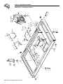
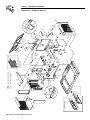
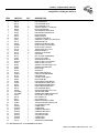
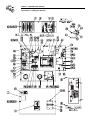
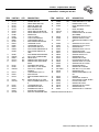
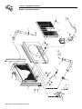
Section 7 — EXPLODED VIEWS AND
PARTS LISTS ..............................28
Section 8 — INSTALLATION DIAGRAM ..........44
2.10 Battery Installation ..............................................11
2.11 Preparation Before Start-Up ................................12
Generac® Power Systems, Inc.
1
IMPORTANT SAFETY INSTRUCTIONS
QUIETSOURCE™ Liquid-cooled 30 kW Generators
!
SAVE THESE INSTRUCTIONS – The manufacturer suggests that these rules for safe
operation be copied and posted in potential hazard areas. Safety should be stressed to all
operators, potential operators, and service and repair technicians for this equipment.
!
SAVE THESE INSTRUCTIONS – This manual contains important instructions that should be
followed during installation and maintenance of the generator and batteries.
!
!
WARNING:
The engine exhaust from this product
contains chemicals known to the state
of California to cause cancer, birth
defects or other reproductive harm.
!
WARNING:
!
This product contains or emits chemicals
known to the state of California to cause
cancer, birth defects or other reproductive harm.
Study these SAFETY RULES carefully before installing,
operating or servicing this equipment. Become familiar
with this Owner’s Manual and with the unit. The generator can operate safely, efficiently and reliably only if
it is properly installed, operated and maintained. Many
accidents are caused by failing to follow simple and
fundamental rules or precautions.
Generac cannot possibly anticipate every possible circumstance that might involve a hazard. The warnings in
this manual, and on tags and decals affixed to the unit
are, therefore, not all-inclusive. If using a procedure,
work method or operating technique that Generac does
not specifically recommend, ensure that it is safe for
others. Also make sure the procedure, work method or
operating technique chosen does not render the generator unsafe.
DANGER
!
Despite the safe design of this generator,
operating this equipment imprudently, neglecting
its maintenance or being careless can cause
possible injury or death. Permit only responsible
and capable persons to install, operate or maintain this equipment.
Potentially lethal voltages are generated by these
machines. Ensure all steps are taken to render the
machine safe before attempting to work on the
generator.
!
2
Parts of the generator are rotating and/or hot
during operation. Exercise care near running generators.
Generac® Power Systems, Inc.
!
!
! GENERAL HAZARDS !
• For safety reasons, Generac recommends that this
equipment be installed, serviced and repaired by a
Generac Authorized Service Dealer or other competent, qualified electrician or installation technician
who is familiar with applicable codes, standards and
regulations. The operator also must comply with all
such codes, standards and regulations.
• Installation, operation, servicing and repair of this
(and related) equipment must always comply with
applicable codes, standards, laws and regulations.
Adhere strictly to local, state and national electrical
and building codes. Comply with regulations the
Occupational Safety and Health Administration
(OSHA) has established. Also, ensure that the generator is installed, operated and serviced in accordance
with the manufacturer’s instructions and recommendations. Following installation, do nothing that might
render the unit unsafe or in noncompliance with the
aforementioned codes, standards, laws and regulations.
• The engine exhaust fumes contain carbon monoxide
gas, which can be DEADLY. This dangerous gas, if
breathed in sufficient concentrations, can cause
unconsciousness or even death. For that reason, adequate ventilation must be provided. Exhaust gases
must be piped safely away from any building or
enclosure that houses the generator to an area where
people, animals, etc., will not be harmed. This
exhaust system must be installed properly, in strict
compliance with applicable codes and standards.
• Keep hands, feet, clothing, etc., away from drive belts,
fans, and other moving or hot parts. Never remove
any drive belt or fan guard while the unit is operating.
• Adequate, unobstructed flow of cooling and ventilating air is critical to prevent buildup of explosive gases
and to ensure correct generator operation. Do not
alter the installation or permit even partial blockage
of ventilation provisions, as this can seriously affect
safe operation of the generator.
• Keep the area around the generator clean and uncluttered. Remove any materials that could become hazardous.
• When working on this equipment, remain alert at all
times. Never work on the equipment when physically
or mentally fatigued.
IMPORTANT SAFETY INSTRUCTIONS
QUIETSOURCE™ Liquid-cooled 30 kW Generators
• Inspect the generator regularly, and promptly repair
or replace all worn, damaged or defective parts using
only factory-approved parts.
• Before performing any maintenance on the generator,
disconnect its battery cables to prevent accidental
start-up. Disconnect the cable from the battery post
indicated by a NEGATIVE, NEG or (–) first.
Reconnect that cable last.
• Never use the generator or any of its parts as a step.
Stepping on the unit can stress and break parts, and
may result in dangerous operating conditions from
leaking exhaust gases, fuel leakage, oil leakage, etc.
ELECTRICAL HAZARDS
• All generators covered by this manual produce dangerous electrical voltages and can cause fatal electrical
shock. Utility power delivers extremely high and dangerous voltages to the transfer switch as well as the
standby generator. Avoid contact with bare wires, terminals, connections, etc., on the generator as well as
the transfer switch, if applicable. Ensure all appropriate covers, guards and barriers are in place before
operating the generator. If work must be done around
an operating unit, stand on an insulated, dry surface
to reduce shock hazard.
• Do not handle any kind of electrical device while
standing in water, while barefoot, or while hands or
feet are wet. DANGEROUS ELECTRICAL SHOCK
MAY RESULT.
• If people must stand on metal or concrete while
installing, operating, servicing, adjusting or repairing
this equipment, place insulative mats over a dry
wooden platform. Work on the equipment only while
standing on such insulative mats.
• The National Electrical Code (NEC), Article 250
requires the frame and external electrically conductive parts of the generator to be connected to an
approved earth ground and/or grounding rods. This
grounding will help prevent dangerous electrical
shock that might be caused by a ground fault condition in the generator set or by static electricity. Never
disconnect the ground wire.
• Wire gauge sizes of electrical wiring, cables and cord
sets must be adequate to handle the maximum electrical current (ampacity) to which they will be subjected.
• Before installing or servicing this (and related) equipment, make sure that all power voltage supplies are
positively turned off at their source. Failure to do so
will result in hazardous and possibly fatal electrical
shock.
• Connecting this unit to an electrical system normally
supplied by an electric utility shall be by means of a
transfer switch so as to isolate the generator electric
system from the electric utility distribution system
when the generator is operating. Failure to isolate the
two electric system power sources from each other by
such means will result in damage to the generator
and may also result in injury or death to utility power
workers due to backfeed of electrical energy.
• Generators installed with an automatic transfer
switch will crank and start automatically when NORMAL (UTILITY) source voltage is removed or is below
an acceptable preset level. To prevent such automatic start-up and possible injury to personnel, disable
the generator’s automatic start circuit (battery cables,
etc.) before working on or around the unit. Then,
place a “Do Not Operate” tag on the generator control
panel and on the transfer switch.
• In case of accident caused by electric shock, immediately shut down the source of electrical power. If this
is not possible, attempt to free the victim from the
live conductor. AVOID DIRECT CONTACT WITH
THE VICTIM. Use a nonconducting implement, such
as a dry rope or board, to free the victim from the live
conductor. If the victim is unconscious, apply first aid
and get immediate medical help.
• Never wear jewelry when working on this equipment.
Jewelry can conduct electricity resulting in electric
shock, or may get caught in moving components
causing injury.
FIRE HAZARDS
• Keep a fire extinguisher near the generator at all
times. Do NOT use any carbon tetra-chloride type
extinguisher. Its fumes are toxic, and the liquid can
deteriorate wiring insulation. Keep the extinguisher
properly charged and be familiar with its use. If there
are any questions pertaining to fire extinguishers,
consult the local fire department.
EXPLOSION HAZARDS
• Properly ventilate any room or building housing the
generator to prevent build-up of explosive gas.
• Do not smoke around the generator. Wipe up any fuel
or oil spills immediately. Ensure that no combustible
materials are left in the generator compartment, or
on or near the generator, as FIRE or EXPLOSION
may result. Keep the area surrounding the generator
clean and free from debris.
• Generac generator sets may operate using one of several types of fuels. All fuel types are potentially FLAMMABLE and/or EXPLOSIVE and should be handled
with care. Comply with all laws regulating the storage
and handling of fuels. Inspect the unit’s fuel system
frequently and correct any leaks immediately. Fuel
supply lines must be properly installed, purged and
leak tested according to applicable fuel-gas codes
before placing this equipment into service.
• Diesel fuels are highly FLAMMABLE. Gaseous fluids
such as natural gas and liquid propane (LP) gas are
extremely EXPLOSIVE. Natural gas is lighter than air,
and LP gas is heavier than air; install leak detectors
accordingly.
Generac® Power Systems, Inc.
3
Section 1 - General Information
QUIETSOURCE™ Liquid-cooled 30 kW Generators
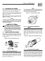
1.1
GENERATOR
1.3
This equipment is a liquid-cooled, engine-driven generator set. The generator is designed to supply electrical power that operates critical electrical loads
during utility power failure. The unit has been factory-installed in a weather resistant, all aluminum
enclosure and is intended for outdoor installation
only. Use this generator as a source of electrical
power for the operation of 120 and/or 240VAC, single-phase loads.
!
1.2
If this generator is used to power electrical
load circuits normally powered by a UTILITY
power source, it is required by code to install
a transfer switch. The transfer switch must
effectively isolate the electric system from the
utility distribution system when the generator
is operating (NEC 701). Failure to isolate an
electrical system by such means results in
damage to the generator and may also result
in injury or even death to utility power workers due to backfeed of electrical energy.
TRANSFER SWITCH
This generator system may include a matched automatic transfer switch which is intended to be used in
conjunction with the Generac generator. It is supplied
in either a NEMA 1 enclosure or a NEMA 3R enclosure. The NEMA 1 enclosure is intended for indoor
use only. The NEMA 3R enclosure is weather proof
and can be used indoors or outdoors. Follow these
rules:
AUTOMATIC SYSTEM OPERATION
When this generator, along with a transfer switch, has
been installed and interconnected, a circuit board in
the generator panel constantly monitors UTILITY
power source voltage. Should that voltage drop below
a preset value, and remain at such a low state for a
preset amount of time, the generator cranks and
starts. After the generator starts, the transfer switch
transfers load circuits so the generator can power
them.
When utility source voltage has been restored, the
switch re-transfers back to the UTILITY source voltage and the generator then shuts down.
Please reference the transfer switch manual for specific information.
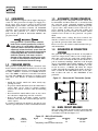
1.4
GENERATOR AC CONNECTION
SYSTEMS
The generator was shipped from the factory with its
stator AC output leads connected in a single-phase,
three-wire generator AC connection system (Figure
1.1). The stator assembly in this system consists of a
pair of stationary windings, with two leads brought
out of each winding. Each single winding can supply
120VAC, 60 Hertz. When the two windings are connected in series, a 240VAC, 60 Hertz AC output
results. Typically the two HOT leads in the circuit are
wires 11 and 44. The NEUTRAL leads are the junction of Wires 22 and 33. The NEUTRAL is not
grounded.
Figure 1.1 - Generator AC Connection System
• Install the transfer switch on a firm, sturdy supporting structure.
• To prevent switch distortion, level the switch if necessary. This can be done by placing washers
between the switch enclosure and the mounting
surface.
• Never install the switch where water or any corrosive substance might drip onto the enclosure.
• Protect the switch at all times against excessive
moisture, dust, dirt, lint, construction grit and corrosive vapors.
If a transfer switch is not included, one may be purchased separately from a Generac Authorized Dealer.
1.5
MAIN CIRCUIT BREAKER
The generator’s main circuit breaker is included with
the unit as shipped from the factory. The breaker for
each unit is described in Figure 1.2.
Figure 1.2 - Main Circuit Breaker
4
Model
Rating
004917-0
27,000 NG
30,000 LP
Phase
Generac® Power Systems, Inc.
Actual Current
C/B Rating*
1
112.5
1
125.0
* Amp Rating of C/B structured under model.
150
150
Circuit Breaker
150A QN2
150A QN2
Section 1 - General Information
QUIETSOURCE™ Liquid-cooled 30 kW Generators
1.6
NOTE:
GENERATOR FUEL SYSTEM
The unit has been factory tested and adjusted using a
natural gas fuel system. If propane (LP) gas is necessary. Refer to Section 1.11, Fuel Consumption.
The Low Oil Pressure, High Coolant Temperature
and Low Coolant Level are not monitored for the
first 10 seconds of engine run time.
Fuel pressure for a natural gas set up should be five
inches to 14 inches of water column (0.18 to 0.5
psi) at all load ranges.
Figure 1.4 - Low Oil Pressure Switch
Fuel pressure for an LP vapor set up should be 11
inches to 14 inches of water column (0.4 to 0.5
psi) at all load ranges.
NOTE:
A seperate gas line and regulator may be needed
to assure proper gas pressure to the generator.
Improper gas pressure can cause hard starting and
affect engine durability.
Gaseous fuels such as natural and LP (propane)
gas are highly explosive. Even the slightest
spark can ignite such fuels and cause an explosion. No leakage of fuel is permitted. Natural
gas, which is lighter than air, tends to collect in
high areas. LP gas is heavier than air and tends
to settle in low areas.
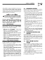
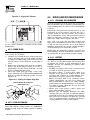
1.7
ENGINE PROTECTIVE DEVICES
The engine has several safety switches which cause
the engine to automatically shut down under the following conditions: low oil pressure, high coolant temperature, engine overspeed, low coolant level or overcrank (Figure 1.3).
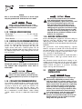
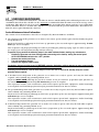
1.7.2
HIGH COOLANT TEMPERATURE
SWITCH
This normally open (N.O.) thermostatic switch has
sensing tip which is immersed in captive coolant.
Should coolant temperature exceed about 230°F
(110°C), the switch contacts close. This causes the
engine to shut down automatically and turns on the
high coolant temperature/low coolant level LED
(Figure 1.5).
Figure 1.5- High Coolant Temperature Switch
Figure 1.3 - Engine Protective Devices
LOW OIL
PRESURE
SWITCH
LOW COOLANT
LEVEL SWITCH
HIGH
COOLANT
TEMPERATURE
SWITCH
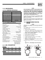
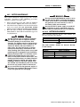
1.7.1
LOW OIL PRESSURE SWITCH
This switch is normally-closed (N.C.), but is held
open by engine oil pressure during engine running.
Should operating oil pressure drop below about 8-10
psi (55-68 kPa), the switch contacts close, the engine
shuts down automatically, and the low oil pressure
LED is turned ON (Figure 1.4).
1.7.3
LOW COOLANT LEVEL SWITCH
Should engine coolant level drop below the level of
the high coolant temperature switch, it is possible for
the engine to overheat without automatic shutdown.
To prevent such overheating without automatic shut
down, the engine has a low coolant level sensor. If the
engine coolant drops too low, the engine automatically shuts down and turns on the high coolant temperature/low coolant level LED (Figure 1.6 on page 6).
Generac® Power Systems, Inc.
5
Section 1 — General Information
QUIETSOURCE™ Liquid-cooled 30 kW Generators
Figure 1.6 - Low Coolant Level Sensor
1.7.7
LOW BATTERY
The engine control board continually monitors the
battery voltage and turns on the low battery LED if
the battery voltage falls below 11.0 VDC for one
minute. Low battery voltage is a non-latching alarm,
which will automatically clear if the battery voltage
rises above 11.0 VDC.
1.7.4
The control system will not attempt to start the
engine if there is a low battery condition, however, if
the engine is already running when the low battery
condition occurs, the engine will continue to run as
long as possible.
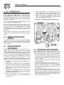
OVERSPEED SHUTDOWN
The engine control board receives AC frequency signals from an engine run winding in the alternator.
Should AC frequency exceed about 72 Hertz for three
seconds or 75 Hertz instantaniously, the engine shuts
down and the overspeed LED turns on. Should AC
frequency exceed about 72 Hertz, circuit board action
will automatically shutdown the engine (Figure 1.7).
Figure 1.7 - Printed Circuit Board Assembly
R44
LED1
C27
Q2
2
C9
J2
C26
U7
C4
D10
C21
C30
Battery voltage is NOT monitored during the crank
cycle.
1.7.8
If the engine control board shuts down the generator
for any of the above reasons, the engine remains
stopped until the alarm is cleared by placing the
AUTO/OFF/MANUAL switch into the OFF position.
1.7.9
RL1
R25
UNPACKING
1.8.1
RL2
R1
R48
DC FUSE
These fuses are located on the front panel of the control system. They protect the panel wiring and components from damaging overload. Always remove the
15 amp main fuse before working on the generator.
The unit will not start or crank if this fuse is blown.
Replace the fuse with one of the same size, type, and
rating (main AGC-15, battery charger AG4).
1.8
C2
ALARM RESET
UNPACKING PRECAUTIONS
D17
R49
U1
J1
L3
. V E R 6 0 94 E 0 # B C P
1.7.5
D19
RPM SENSOR LOSS
If the engine control board does not receive a proper
rpm signal from the starter during cranking or running, it shuts down the engine on rpm sensor loss
and flash the overspeed LED.
1.7.6
OVERCRANK SHUTDOWN
The engine control board uses a cyclic cranking
process when attempting to start the engine. The first
crank cycle is a 15-second crank followed by a sevensecond rest. This is followed by five more crank
cycles each with a seven second crank followed by a
seven second rest.
If the engine fails to start after all six attempts, the
start attempt is stopped and the overcrank LED
turned on.
6
Generac® Power Systems, Inc.
Handle shipping cartons and crates with care. Use
care to avoid damage from dropping, bumping, collision, etc. Store and unpack cartons with the proper
side up, as noted on the shipping carton.
1.8.2
INSPECTION
After unpacking, carefully inspect the generator for
any damage that may have occurred during shipment. If loss or damage is noted at the time of delivery, have the person(s) making delivery note all damage on the freight bill or affix their signature under
the consignor’s memo of loss or damage.
1.9
!
LIFTING THE GENERATOR
When lifting or hoisting equipment is used,
be careful not to touch overhead power lines.
The generators weight of more than 900
pounds requires proper tools, equipment, and
qualified personnel to be used in all phases of
handling and unpacking.
Section 1 — General Information
QUIETSOURCE™ Liquid-cooled 30 kW Generators
NOTE:
1.10 SPECIFICATIONS
1.10.1 GENERATOR SPECIFICATIONS
Single-phase
4917-0
27 (NG), 30 (LP)
Model
Rated Max. Cont.
AC Power Output (kW)
Rated voltage (volts)
120/240
No. of Rotor Poles
4
Driven Speed of Rotor
1800
Rotor Excitation System Direct excited brush type
Type of Stator
4 Wire
Rotor/Stator Insulation
Class F/H
1.10.2 ENGINE SPECIFICATIONS
Make ......................................................................................Ford
Displacement ..................................................................3.0 liters
Cylinder Arrangement ..............................................................V-6
Valve Arrangement ..............................................Overhead Valve
Firing Order ................................................................1-4-2-5-3-6
Number of Main Bearings............................................................4
Compression Ratio............................................................9.3 to 1
No. of Teeth on Flywheel ........................................................164
Ignition Timing at 1800 rpm..............................30 degrees BTDC
Spark Plug Gap ..................................................0.035-0.045 inch
Recommended Spark Plugs
Motor Craft..........................................................AG, SF 32PGM
Oil Pressure....................................................................40-50 psi
Crankcase Oil Capacity........................5.0 U.S. quarts (4.7 liters)
Recommended Engine Oil..........................................SAE 5W-20
Type of Cooling System ..................Pressurized, closed recovery
Cooling Fan ..............................................................Pusher Type
Cooling System Capacity..................3.0 U.S. gallons (11.4 liters)
Recommended Coolant ............................Use a 50-50 mixture of
ethylene glycol base
and de-ionized water.
Fuel consumption is given at rated maximum continuous power output when using natural gas rated
at 1000 Btu per cubic foot. LP gas is rated at 2520
Btu per cubic foot. Actual fuel consumption
obtained may vary depending on such variables as
applied load, ambient temperature, engine conditions and other environmental factors.
Fuel pressure for a natural gas set up should be five
inches to 14 inches of water column (0.18 to 0.5
psi) at all load ranges.
Fuel pressure for an LP vapor set up should be 11
inches to 14 inches of water column (0.4 to 0.5
psi) at all load ranges.
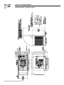
1.12 RECONFIGURING THE FUEL
SYSTEM
NOTE:
All models are configured for natural gas from the
factory.
To reconfigure the fuel system from NG to LP vapor,
follow these steps:
1. Turn the main gas supply off.
2. Remove the carburetor fuel hose from the outlet
port (Port 1) of the demand regulator (Figure 1.8).
3. Remove the brass hose fitting from the outlet port
(Port 1) of the demand regulator.
4. Remove pipe plug from Port 2.
5. Install brass hose fitting into Port 2.
6. Install pipe plug into Port 1.
7. Connect carburetor gas hose to brass fitting.
8. Tighten all clamps and plugs.
9. Make sure fuel supply is of the proper pressure
and type for configuration.
10. Reverse the procedure to convert back to natural
gas.
Figure 1.8 — Reconfigure the Fuel System
Natural Gas:
% of Load
m3/hr
ft3/hr
LP Vapor:
% of Load
m3/hr
ft3/hr
Port 2
Port 1
1.11 FUEL CONSUMPTION
PLUG
25%
3.1
110.3
50%
5.9
209.0
75%
8.5
299.5
100%
11.0
387.0
25%
1.3
45.6
50%
2.4
86.4
75%
3.5
123.8
100%
4.5
160.0
FUEL HOSE
FUEL HOSE
BRASS HOSE
FITTING
OUT
PORT 1
BRASS HOSE
FITTING
HOUSING
PORTS
NG FUEL SYSTEM
PLUG
OUT
PORT 2
HOUSING
PORTS
LP FUEL SYSTEM
Generac® Power Systems, Inc.
7
Section 2 — Installation
QUIETSOURCE™ Liquid-cooled 30 kW Generators
NOTE:
Port 1 is for NG only and Port 2 is for LP vapor
only. No provision for dual fuel has been made.
DANGER
!
!
Serious injury or damage may occur if not
configured properly. Please consult an authorized Generac Service Dealer with any questions.
1.13 TORQUE SPECIFICATIONS
Cylinder Head ............................................15 (+ 90° + 90°) ft.lb.
Intake Manifold ................................................................13 ft.lb.
Exhaust Manifold..............................................................13 ft.lb.
1.14 ENGINE OIL RECOMMENDATIONS
The unit has been filled with 5W-20 engine oil at the
factory. Use a high-quality detergent oil classified “For
Service CC, SD, SE, SF.” Detergent oils keep the
engine cleaner and reduce carbon deposits. Use oil
having the following SAE viscosity rating, based on
the ambient temperature range anticipated before the
next oil change:
Temperature
Above 80° F (27° C)
32° to 80° F (-1° to 27° C)
Below 32° F (0° C)
Oil Grade (Recommended)
SAE 5W-20
SAE 5W-20
SAE 5W-20
NOTE:
5W-30 full synthetic oil is highly recommended in
any element with temperatures above 90°F or
below 30°F.
1.16 BEFORE INSTALLATION
Before installing this equipment, check the ratings of
both the generator and the transfer switch. Read
“Emergency Isolation Method” and “Total Circuit
Isolation Method” in the installation manual (Part No.
079699).
The generator’s rated wattage/amperage capacity
must be adequate to handle all electrical loads that
the unit will power. The critical (essential) loads may
need to be grouped together and wired into a separate “emergency” distribution panel.
This generator can be installed in conjunction with a
standard Generac “GTS” type transfer switch, if necessary.
The standard transfer switch has no sensing or controlling circuit boards. Instead, the generator control
console houses a “Printed Circuit Board Assembly”,
which controls all phases of operation, including
engine start up and load transfer.
2.1
!
Any attempt to crank or start the engine
before it has been properly serviced with the
recommended oil may result in an engine failure.
1.15 COOLANT RECOMMENDATIONS
Use a mixture of half low silicate ethylene glycol base
anti-freeze and half de-ionized water. Cooling system
capacity is about 12 U.S. quarts (11.4 liters). Use
only de-ionized water and only low silicate antifreeze. If desired, add a high quality rust inhibitor to
the recommended coolant mixture. When adding
coolant, always add the recommended 50-50 mixture.
8
Generac® Power Systems, Inc.
Do not use any chromate base rust inhibitor
with ethylene glycol base anti-freeze or
chromiumhydroxide (“green slime”) forms and
will cause overheating. Engines that have
been operated with a chromate base rust
inhibitor must be chemically cleaned before
adding ethylene glycol base anti-freeze. Using
any high silicate anti-freeze boosters or additives will also cause overheating. It is also recommend that any soluble oil inhibitor is NOT
USED for this equipment.
STANDBY GENERATOR
INSTALLATION
DANGER
Connecting this generator to an electrical system normally supplied by an electric utility
shall be by means of a transfer switch, so as to
isolate the electric system from the utility distribution system when the generator is operating.
Failure to isolate the electric system by these
means will result in damage to the generator
and may also result in injury or death to utility
workers due to backfeed of electrical energy.
If an open bottom is used, the engine-generator is to be installed over non-combustible
materials and should be located such that combustible materials are not capable of accumulating under the generator set.
Section 2 — Installation
QUIETSOURCE™ Liquid-cooled 30 kW Generators
Only qualified, competent installation contractors or
electricians thoroughly familiar with applicable
codes, standards and regulations should install this
standby electric power system. The installation must
comply strictly with all codes, standards and regulations pertaining to the installation.
After the system has been installed, do nothing
that might render the installation in noncompliance with such codes, standards and regulations.
NOTE:
For more information about the installation of a
standby system, order Engine-Generator Standby
Electric Power Systems Installer’s Guide and
Reference Manual (part #046622) from the
Generac Authorized Service Dealer.
!
2.1.1
NFPA STANDARDS
The following published standards booklets pertaining to standby electric systems are available form the
National Fire Protection Association (NFPA),
Batterymarch Park, Quincy, MA 02269:
• NFPA No. 37, STATIONARY COMBUSTION
ENGINES AND GAS TURBINES.
• NFPA No. 76A, ESSENTIAL ELECTRICAL SYSTEMS FOR HEALTH CARE FACILITIES.
• NFPA No. 220, STANDARD TYPES OF BUILDING
CONSTRUCTION
• NFPA No. 68, GUIDE FOR EXPLOSION VENTING
• NFPA No. 70, NATIONAL ELECTRICAL CODE.
• NFPA No. 30, FLAMMABLE AND COMBUSTIBLE
LIQUIDS CODE.
• NFPA No. 10, INSTALLATION, MAINTENANCE AND
USE OF PORTABLE FIRE EXTINGUISHERS.
2.1.2
OTHER PUBLISHED STANDARDS
In addition to NFPA standards, the following information pertaining to the installation and use of
standby electric systems is available:
• Article X, NATIONAL BUILDING CODE, available
from the American Insurance Association, 85 John
Street, New York, N.Y. 10038.
• AGRICULTURAL WIRING HANDBOOK, obtainable
from the Food and Energy Council, 909 University
Avenue, Columbia, MO, 65201.
• ASAE EP-364.2, INSTALLATION AND MAINTENANCE OF FARM STANDBY ELECTRIC POWER,
available from the American Society of Agricultural
Engineers, 2950 Niles Road, St. Joseph, MI 49085.
• A52.1, AMERICAN NATIONAL STANDARD FOR
CHIMNEYS, FIREPLACES AND VENTING SYSTEMS, available from the American National
Standard Institute, 1430 Broadway, New York, N.Y.
10018.
2.2
GENERATOR LOCATION
Install the generator set, in its protective enclosure
outdoors, where adequate cooling and ventilating air
always is available. Consider these factors:
• Install the unit where air inlet and outlet openings
will not become obstructed by leaves, grass, snow,
etc. If prevailing winds will cause blowing or drifting, consider using a windbreak to protect the unit.
• Install the generator on high ground where water
levels will not rise and endanger it.
• This genset must be installed on a level surface.
The base frame must be level within 1/2 inch all
around.
• Allow sufficient room on all sides of the generator
for maintenance and servicing. A good rule is to
allow five feet of space on all sides.
• Where strong prevailing winds blow from one
direction, face the generator air inlet openings into
the prevailing winds.
• Install the generator as close as possible to the
transfer switch. This reduces the length of wiring
and conduit.
• Install the generator as close as possible to the fuel
supply, to reduce the length of piping. HOWEVER,
REMEMBER THAT LAWS OR CODES MAY REGULATE THE DISTANCE.
2.3
GENERATOR MOUNTING AND
SUPPORT
Retain the generator compartment to a concrete slab
with 1/4-inch masonry type anchor bolts. Be sure the
bolts are long enough to retain the compartment. The
slab should be at least six inches thick and should
extend beyond the enclosure to a distance of at least
three inches on all sides. See Section 6 for generator
major dimensions.
2.4
BASIC STANDBY ELECTRIC
SYSTEM
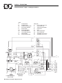
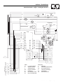
Figure 2.1 shows a schematic diagram of a basic
standby electric system. Both the UTILITY power
supply and the STANDBY (GENERATOR) output are
connected to an approved transfer switch. The transfer switch is required by electrical code and serves
the following functions:
• Allows the LOAD circuits to be connected to only
one power supply at a time.
• Prevents electrical backfeed between the generator
and the UTILITY power circuits.
Both the STANDBY and the UTILITY power supplies
to the transfer switch are protected against overload
by a main line circuit breaker.
Generac® Power Systems, Inc.
9
Section 2 — Installation
QUIETSOURCE™ Liquid-cooled 30 kW Generators
Figure 2.1 – Basic Standby Electric System
2.7
GROUNDING THE GENERATOR
The National Electrical Code requires the frame and
external electrically conductive parts of this equipment to be properly connected to an approved earth
ground and/or grounding rods. For that purpose, a
GROUND LUG (Figure 2.2) is provided on the generator mounting base. Consult a qualified electrician
for grounding requirements in the area. Grounding
procedures must meet local regulations.
DANGER
2.5
EMERGENCY CIRCUIT ISOLATION
METHOD
This prevents overloading the generator by keeping
electrical loads below the wattage/amperage capacity
of the generator. If the generator is powering only critical loads, within the wattage/amperage capacity, during utility power outages, consider using the emergency circuit isolation method.
Do not connect the ground wire to any pipe
that carries a flammable or explosive substance
– FIRE or an EXPLOSION may result.
Proper grounding helps protect personnel against
electrical shock in the event of a ground fault condition in the generator or in connected electrical
devices. In addition, grounding helps dissipate static
electricity that often builds up in ungrounded
devices.
Figure 2.2 – Generator Grounding Lug (typical)
Critical electrical loads are grouped together and
wired into a separate “Emergency Distribution
Panel.” Load circuits powered by that panel are within the wattage/amperage capacity of the generator set.
When this method is used, it is difficult to overload
the generator. The transfer switch must meet the following requirements:
• It must have an ampere rating equal to the total
amperage rating of the emergency distribution
panel circuit.
• Have it installed between the building’s main distribution panel and the emergency distribution
panel.
2.6
TOTAL CIRCUIT ISOLATION
METHOD
When a generator capable of powering all electrical
loads in the circuit is to be installed, use the “Total
Circuit Isolation Method.” It is possible for the generator to be overloaded when this isolation method is
employed. The following apply to the transfer switch
in this type of system.
• Ampere rating of the transfer switch must equal
the ampere rating of the normal incoming utility
service.
• The transfer switch is installed between the utility
service entrance and the building distribution
panel.
10 Generac® Power Systems, Inc.
GROUNDING
LUG
2.8
GENERATOR AC NEUTRAL
CONNECTIONS
Generac uses an UNGROUNDED AC neutral.
Grounding is recommended only at the main service
entrance. If the neutral wire is grounded and one of
the phase loads becomes grounded, the excessive
current opens the load circuit breaker or collapses
the generator field. The actual result depends on the
electrical characteristics of the particular installed
generator.
2.9
TRANSFER SWITCH SIGNAL
CONNECTIONS
2.9.1
PRE-PACKAGED ATS
If the generator is to be installed with a pre-packaged
transfer switch, it is necessary to connect the control
wires to the generator and set position two of the
four-position dip switch to OFF.
Section 2 — Installation
QUIETSOURCE™ Liquid-cooled 30 kW Generators
Setting switch two to OFF allows the control PCB to
perform the ATS control functions.
!
Control system interconnections consist of N1 and
N2, and leads 23 and 194. Control system interconnection leads must be run in a conduit that is separate from the AC power leads. Recommended wire
gauge sizes for this wiring depends on the length of
the wire, as recommended below:
MAXIMUM WIRE LENGTH
460 feet (140m)
461 to 730 feet (223m)
731 to 1,160 feet (354m)
1,161 to 1,850 feet (565m)
2.9.2
RECOMMENDED WIRE
SIZE
No. 18 AWG.
No. 16 AWG.
No. 14 AWG.
No. 12 AWG.
Connect the two-wire start signal from the automatic
transfer switch to the automatic start connection,
which is located in the middle, on the bottom, inside
the control panel. Match wires 178 and 183 in the
transfer switch to 178 and 183 on the terminal strip
in the control panel. The conductors for the two-wire
start circuit must be in their own conduit. (See
Section 3.1 for further explanation.)
2.10 BATTERY INSTALLATION
DANGER
!
Do not dispose of the battery in a fire. The battery is capable of exploding.
!
Standby generators installed with automatic
transfer switches will crank and start automatically when NORMAL (UTILITY) source voltage is
removed or is below an acceptable preset level.
To prevent such automatic start-up and possible
injury to personnel, do not connect battery
cables until certain that normal source voltage
at the transfer switch is correct and the system
is ready to be placed into operation.
Storage batteries give off explosive hydrogen
gas. This gas can form an explosive mixture
around the battery for several hours after
charging. The slightest spark can ignite the gas
and cause an explosion. Such an explosion can
shatter the battery and cause blindness or
other injury. Any area that houses a storage
battery must be properly ventilated. Do not
allow smoking, open flame, sparks or any spark
producing tools or equipment near the battery.
Do not open or mutilate the battery. Released
electrolyte can be toxic and harmful to the skin
and eyes.
The battery represents a risk of high short circuit
current. When working on the battery, always
remove watches, rings or other metal objects,
and only use tools that have insulated handles.
GTS-TYPE ATS
If the generator is to be installed with an automatic
transfer switch, such as a Generac GTS-type switch,
it is necessary to connect the two-wire start control
system.
Battery electrolyte fluid is an extremely caustic
sulfuric acid solution that can cause severe
burns. Do not permit fluid to contact eyes, skin,
clothing, painted surfaces, etc. Wear protective
goggles, protective clothing and gloves when
handling a battery. If fluid is spilled, flush the
affected area immediately with clear water.
2.10.1 VENTED BATTERIES
The electrolyte is a dilute sulfuric acid that is
harmful to the skin and eyes. It is electrically
conductive and corrosive. The following procedures are to be observed:
• Wear full eye protection and protective clothing,
• Where electrolyte contacts the skin, wash it off
immediately with water,
• Where electrolyte contacts the eyes, flush thoroughly and immediately with water and seek medical attention, and
• Spilled electrolyte is to be washed down with an
acid-neutralizing agent. A common practice is to
use a solution of one pound (500 grams) bicarbonate of soda to one gallon (4 liters) of water. The
bicarbonate of soda solution is to be added until
the evidence of reaction (foaming) has ceased. The
resulting liquid is to be flushed with water and the
area dried.
Lead acid batteries present a risk of fire
because they generate hydrogen gas. The following procedure are to be followed:
• DO NOT SMOKE when near batteries,
• DO NOT cause flame or spark in battery area, and
• Discharge static electricity from body before touching batteries by first touching a grounded metal
surface.
Servicing of batteries is to be performed or supervised by personnel knowledgeable of batteries and
the required precautions. Keep unauthorized personnel away from batteries.
!
The recommended battery is Group 26, 12VDC, 550
CCA/75 AH minimum. All batteries must be at 100
percent state-of-charge before they are installed on
the generator.
Generac® Power Systems, Inc. 11
Section 3 — Operation
QUIETSOURCE™ Liquid-cooled 30 kW Generators
When using maintenance-free batteries, it is not necessary to check the specific gravity or electrolyte level.
Have these procedures performed at the intervals
specified in Section 4, “Maintenance.” A negative
ground system is used. Battery connections are
shown on the wiring diagrams. Make sure all batteries are correctly connected and terminals are tight.
Observe battery polarity when connecting batteries to
the generator set.
NOTE:
Damage will result if the battery connections are
made in reverse.
2.11 PREPARATION BEFORE START-UP
The instructions in this section assume that the standby generator has been properly installed, serviced,
tested, adjusted and otherwise prepared for use by a
competent, qualified installation contractor. Be sure to
read the “Safety Rules” on Pages 2 and 3, as well as all
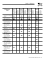
other safety information in this manual, before
attempting to operate this (and related) equipment.
2.11.1 PRIOR TO INITIAL START-UP
Prior to initially starting the generator, it must
be properly prepared for use. Any attempt to
crank or start the engine before it has been
properly serviced with the recommended types
and quantities of engine fluids (oil, coolant,
fuel, etc.) may result in an engine failure.
Before starting the generator for the first time, the
installer must complete the following procedures. For
follow-up maintenance information and/or service
intervals, please refer to Section 4, “Maintenance.”
!
2.11.2 TRANSFER SWITCH
If this generator is used to supply power to any electrical system normally powered by an electric utility,
the National Electrical Code requires that a transfer
switch be installed. The transfer switch prevents electrical backfeed between two different electrical systems (for additional information, see the applicable
transfer switch manual for this unit). The transfer
switch, as well as the generator and other standby
components, must be properly located and mounted
in strict compliance with applicable codes, standards
and regulations.
2.11.3 FUEL SYSTEM
Make sure the fuel supply system to the generator (a)
delivers the correct fuel at the correct pressure and
(b) is properly purged and leak tested according to
code. No fuel leakage is permitted. See
“Specifications” (Section 1.10) for more information.
12 Generac® Power Systems, Inc.
2.11.4 GENERATOR SET LUBRICATION
Check the engine crankcase oil level before operating
and add oil to the proper level – the dipstick “FULL”
mark. Never operate the engine with the oil level
below the dipstick “ADD” mark. See “Specifications”
(Section 1.10) and “Engine Oil Recommendations”
(Section 1.14).
NOTE:
This engine is shipped from the manufacturer
with 5W-20 oil. This oil should be changed after
30 hours of operation.
2.11.5 ENGINE COOLANT
Have the engine cooling system properly filled with
the recommended coolant mixture. Check the system
for leaks and other problems. See “Specifications”
(Section 1.10) and “Coolant” (Section 1.15).
2.11.6 BELT TENSION
Check the engine fan belt tension and condition prior
to placing the unit into service and at recommended
intervals. Belt tension is correct when a force of
approximately 22 pounds (10 kg), applied midway
between pulleys, deflects the belt about 3/8- to 5/8inch (10 to 16 mm).
2.11.7 ELECTRICAL SYSTEM
Make sure the generator is properly connected to an
approved earth ground and/or ground rod.
Make sure the generator battery is fully charged,
properly installed and interconnected, and ready for
use.
Check to ensure that there are no loose electrical connections. Restrain any loose wires to keep them clear
of any moving generator set components.
3.1
USING A STANDARD “GTS”
TRANSFER SWITCH
When required, the pre-packaged standby generator
can be installed with an engineered Generac “GTS”
type automatic transfer switch.
In this application, the GTS is responsible for utility
sensing, weekly exercising, and load transferring.
Position two of the four-position dip switch is used to
turn over this control to the GTS.
Pos2 ON — GTS Application
• The control board will NOT monitor utility.
• The control board will NOT perform a weekly exercise. (The five red LEDs will not flash in this
mode.)
Section 3 - Operation
QUIETSOURCE™ Liquid-cooled 30 kW Generators
• The control board will NOT activate the transfer
output.
• The control board WILL monitor all engine conditions and shut down on all the faults listed in this
document.
Pos2 OFF — ATS Application
• The control board will perform all of the automatic features listed in this document.
• The two-wire start connections should NOT be
used.
3.2.1
Use this three-position switch as follows:
• Set the switch to AUTO for fully automatic operation. See “Automatic Operation” (Section 3.5).
• Set switch to MANUAL position to crank and start
the generator engine.
• Set switch to OFF position to shut down an operating engine. With OFF selected, operation will not
be possible.
DANGER
GTS Mode Operation
When in GTS mode, the control board will respond
as follows based on the AUTO/OFF/MANUAL switch
position.
OFF — The generator will not start and run in this
position.
MANUAL — The control board will start and run the
generator whenever the switch is in the manual position.
AUTO — The control board will monitor the two-wire
start circuit. When a two-wire start is issued the control board will immediately start and run the generator. Whe the two-wire start is removed the control
board will immediately stop the generator.
NOTE:
If the generator is installed in conjunction with an
engineered GTS type transfer switch, refer to the
applicable transfer switch manual for exact operating parameters and timing sequences.
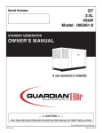
3.2
CONTROL CONSOLE
COMPONENTS
Figure 3.1 - Home Standby Generator Panel
LED INDICATORS:
(SEE OWNER'S MANUAL FOR COMPLETE LED DETAILS)
F
F
OVER CRANK
F
3.2.2
RED LED
E
US
AUTO
OFF
FAULT INDICATOR LED
This LED goes ON when one or more of the following
engine faults occurs and when engine shuts down.
• Low Oil Pressure
• Overcrank
• Low Battery
• Overspeed/RPM Sensor Loss
• High Coolant Temperature/Low Coolant Level
See Section 1.7 for further explanation of engine protection functions.
15 AMP FUSE
This fuse protects the control console’s DC control
circuit against electrical overload. If the fuse has
melted open because of an overload, engine cranking
and startup cannot occur. If the fuse needs to be
replaced, use only an identical 15-amp replacement
fuse. (Type AGC)
3.2.4
FLASHING GREEN LED = NO UTILITY SENSE
5 FLASHING RED LED'S = EXERCISER NOT SET
(IN AUTO MODE ONLY) SOLID GREEN LED = SYSTEM READY, UTILITY POWER ON
RED LED'S = INDIVIDUAL FAULT
E
US
!
With switch set to AUTO, engine can crank
and start suddenly without warning. Such
automatic start up normally occurs when utility source voltage drops below a pre-set level.
To prevent possible injury that might be
caused by such sudden starts, set
AUTO/OFF/MANUAL switch to OFF before
working on or around the unit. Then, place a
“DO NOT OPERATE” tag on control console.
3.2.3
The components of a home standby generator control
console (Figure 3.1) are as follows:
AUTO/OFF/MANUAL SWITCH
4 AMP INLINE FUSE
This fuse protects the battery charger against electrical overload. If the fuse needs to be replaced, use only
an identical 4 amp replacement fuse (type AG).
OFF
SET
EXECISER
TIME
SWITCH
4A FUSE
BATTERY
CHARGER
NOTE:
ON
SET
EXERCISE
TIME
MANUAL
GREEN LED
TO SET EXERCISER TIME
This fuse will not remove the + battery input
power from the PCB when it opens. This means
the exercise timer will not be reset.
1) PLACE AUTO/OFF/MANUAL SWITCH TO AUTO POSITION.
0E7194
AUTO/OFF/MANUAL
SWITCH
15A FUSE
MAIN
POWER
3.2.5
SET EXERCISE TIME SWITCH
This switch allows programming the generator to
start and exercise automatically. “See Weekly
Exercise Cycle.”
Generac® Power Systems, Inc. 13
Section 3 — Operation
QUIETSOURCE™ Liquid-cooled 30 kW Generators
3.2.6
SYSTEM READY LED
The System Ready LED (green) has two main proposes. First, the LED will be ON when the
AUTO/OFF/MANUAL switch is in the AUTO position,
utility is present, and there are no system alarms.
This ON state indicates the system is fully ready for
automatic operation.
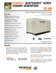
6. Adjust differential pot to make the recovery to
load changes even faster and minimize load
change undershoot and overshoot. If it is set too
high it may introduce oscillations at some load. It
can be set to zero (full CCW) if a small amount
causes oscillations at some load.
Figure 3.2 — Engine Governor Adjustment
The system ready LED will be OFF when the switch
is in the manual or OFF positions.
R44
LED1
C27
Q2
2
C9
The system ready LED is also used to indicate the
presence of utility sensing at the PCB when the switch
is either in the AUTO or MANUAL modes. The LED
will flash at the rate of 1/2 second on, 1/2 second off
if the utility sensing level is below the transfer back
threshold.
J2
C26
U7
C4
D10
C21
This secondary function is only available with dip
switch two in the OFF position (standard ATS application).
C30
C2
RL1
R25
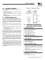
3.3
ENGINE GOVERNOR
ADJUSTMENTS
Engine speed governing is also controlled by the
engine control board. Connector J2 on the engine
control board interfaces with a governor driver module and the Bosch throttle body. The engine governor
has been set by the factory during final testing of the
generator and, in most cases, should not be adjusted.
If, however, adjustments are necessary, or a new
engine control board is installed in the generator, the
following procedure should be followed (Figure 3.2):
1. Set all three potentiometers (pots) fully counterclockwise.
2. Under no load condition, increase the GAIN pot
as much as possible without causeing instability.
3. Apply 1/4, 1/2, 3/4 and full load to the unit.
Decrease the GAIN pot if there is instability at any
load point.
4. Under full load condition, increase the stability
pot until the unit returns to 60 Hertz (or 50 Hertz
in 50 Hertz applications).
5. Reduce load to 3/4, 1/2, 1/4 and no load.
Decrease the stability pot if there is instability at
any load point.
14 Generac® Power Systems, Inc.
R48
D17
MANUAL TRANSFER AND
START-UP
R49
U1
J1
To transfer electrical loads to the Standby (EMERGENCY) power source side and start the engine manually, refer to the Owner’s Manual of the particular
transfer switch.
3.4
RL2
R1
L3
D19
.VER 6094E0 #BCP
DIFFERENTIAL
STABILITY
3.5
DIP SWITCH
1
3
2
4
UNUSED
GTS/ATS
50/60 HZ
POSITION 1
50/60 HZ
ON = 50 HZ
OFF = 60 HZ
POSITION 2
GTS/ATS Select
ON = GTS
OFF = ATS (standard mode)
RETRANSFER AND SHUTDOWN
When utility power source voltage has been restored,
electrical loads may be transferred back to that
source and the generator can be shut down as follows:
• Verify that utility power supply voltage to the transfer switch has been positively turned OFF, using
whatever means provided (such as utility main line
circuit breaker).
• Set the generator’s main circuit breaker to its OFF
or OPEN position.
• Let the generator engine run at no-load for a few
minutes, to stabilize internal unit temperatures.
• On the generator console, set the AUTO/OFF/
MANUAL switch to OFF. Wait for engine to come to
a complete stop.
• For transfer to UTILITY position, refer to the
Owner’s Manual of the particular transfer switch.
• Turn on the utility power supply to the transfer
switch, using whatever means provided (such as a
utility main line circuit breaker). The utility power
source now powers the loads.
Section 4 — Maintenance
QUIETSOURCE™ Liquid-cooled 30 kW Generators
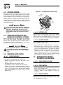
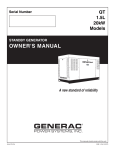
3.6
AUTOMATIC OPERATION
Figure 3.2 - “Set Exercise” Switch
E
F
E
US
If a failure occurs while running in this mode, the five
red LEDs will stop flashing, the individual fault LED
will turn on and the engine will shut down. Once the
AUTO/OFF/MANUAL switch has been switch to OFF,
the individual fault LED will turn OFF and the five
red LEDs will begin flashing to show exercise has still
not been set.
F US
If DC power to the control board is lost, the weekly
exercise setting will be lost. This is indicated by all
five red LEDs continually flashing. In this state the
generator will still start and run in manual mode, or
automatically start and run if UTILITY is lost while in
Auto mode, but it will not perform a weekly exercise
cycle.
US
OFF
The engine control board will start and run the generator once every seven days for approximately 12
minutes. If utility should fail during this exercise
period, the engine control board will transfer the load
to the generator output and continue to run until utility returns.
1. Place the AUTO/OFF/MANUAL switch in the
AUTO position.
2. Press and hold the “Set Exercise” switch for three
seconds, then release.
At this time all five red LEDs will flash for approximately 10 seconds, then the engine will start and run
for it’s 12 minute exercise period, then shut down.
The generator will now start and run each week at the
same time.
FUSE
15A
MAIN
AUTO
WEEKLY EXERCISE CYCLE
On the day, and at the time of day chosen for the generator to exercise, set the weekly exercise cycle as follows:
US
F USE
3.7
FUSE
4A
BAT.
CHARGER
F SE
• Check that load circuits are connected to the
utility power supply.
• Set the AUTO/OFF/MANUAL switch to its AUTO
position.
• Set the generator main circuit breaker to its ON or
CLOSED position.
F
To set the system for fully automatic operation, proceed as follows:
OFF
ON
SET
EXERCISE
TIME
4.1
MANUAL
MAINTENANCE PERFORMED BY
AUTHORIZED SERVICE FACILITIES
A. EVERY THREE MONTHS
1.
2.
3.
4.
5.
6.
Check battery state of charge and condition.
Inspect and test fuel system.
Check transfer switch.
Inspect exhaust system.
Check engine ignition system.
Check fan belts.
B. ONCE EVERY SIX MONTHS
1. Test Engine Safety Devices (low oil pressure, low
coolant level, high coolant temperature).
C. ONCE ANNUALLY
1. Test engine governor. Adjust or repair, if needed.
2. Clean, inspect generator.
3. Flush cooling system.
D. FIRST 100 OPERATING HOURS
1. Change engine oil and oil filter. (After initial
change, service engine oil and filter at 150 operating hours or 6 months, whichever comes first.)
2. Retorque cylinder head. (See Torque Specs,
Section 1.13.)
3. Retorque intake and exhaust manifold. (See
Torque Specs, Section 1.13.)
E. EVERY 500 OPERATING HOURS
1. Service air cleaner.
2. Check starter.
3. Check engine DC alternator.
Generac® Power Systems, Inc. 15
Section 4 — Maintenance
QUIETSOURCE™ Liquid-cooled 30 kW Generators
4.2
COOLING SYSTEM
Figure 4.1 - Oil Dipstick and Oil Fill Cap
Air intake and outlet openings in the generator compartment must be open and unobstructed for continued proper operation. This includes such obstructions as high grass, weeds, brush, leaves and snow.
OIL
DIPSTICK
Without sufficient cooling and ventilating air flow, the
engine/generator quickly overheats, which causes it
to shut down. (See Section 6 for installation drawings
and vent locations.)
The exhaust system parts from this product get
extremely hot and remain hot after shutdown.
High grass, weeds, brush, leaves, etc. must
remain clear of the exhaust. Such materials may
ignite and burn from the heat of the exhaust
system.
4.3
OVERLOAD PROTECTION FOR
ENGINE DC ELECTRICAL SYSTEM
Engine cranking, start up and running are controlled
by a solid state Engine Controller circuit board.
Battery voltage is delivered to that circuit board via a
15 amp fuse. These overcurrent protection devices
will open if the circuit is overloaded.
!
4.4
If a circuit breaker opens or a fuse element
melts, find the cause of the overload before
resetting the circuit breaker or replacing the
fuse.
CHECKING FLUID LEVELS
4.4.1
CHECK ENGINE OIL
Check engine crankcase oil level (Figure 4.1) at least
every 20 hours of operation, or prior to use.
• Remove oil dipstick and wipe dry with a clean,
lint-free cloth.
• Install oil dipstick, then remove again.
• Oil should be between FULL and ADD marks.
• If oil level is below the dipstick ADD mark, remove
oil fill cap. Add the recommended oil to bring oil
level up to the FULL mark. DO NOT FILL ABOVE
THE “FULL” MARK. See Section 1.14 for recommended oils.
OIL
FILL
4.4.2
BATTERY FLUID
Check battery electrolyte fluid at least once weekly.
Fluid should cover separators in all battery cells. If
fluid level is low, add distilled water to cover tops of
separators. DO NOT USE TAP WATER IN BATTERY.
4.4.3
ENGINE COOLANT
Check coolant level in coolant recovery bottle. See
Specifications, Section 1.10.
• Add recommended coolant mixture as necessary.
• Periodically remove radiator pressure cap to make
sure the coolant recovery system is functioning
properly. Coolant should be at bottom of radiator
filler neck. If coolant level is low, inspect gasket in
radiator pressure cap. Replace cap, if necessary.
To have pressure cap tested, contact an authorized
Generac Service Dealer. Inspect cooling system
and coolant recovery system for leaks.
4.5
MAINTENANCE OWNER/
OPERATOR CAN PERFORM
4.5.1
CHECK ENGINE OIL LEVEL
Refer to “Checking Fluid Levels” in Section 4.4.
4.5.2
CHECK BATTERY
• Check battery fluid level each week as outlined
under “Check Fluid Levels”.
• Check battery cables for condition, tightness, corrosion or damage. Clean, tighten or replace as
necessary.
4.5.3
EXERCISE SYSTEM
Start the generator engine at least once every seven
days and let it run at least 20 minutes. See Section
3.6, “Weekly Exercise Cycle”.
16 Generac® Power Systems, Inc.
Section 4 — Maintenance
QUIETSOURCE™ Liquid-cooled 30 kW Generators
4.5.4
INSPECT COOLING SYSTEM
• Inspect engine cooling system at least once each
month.
• Check hoses for damage, deterioration, leaks, etc.
Correct any discrepancies found.
• Check hose clamps for tightness.
4.5.5
CHECK ENGINE COOLANT LEVEL
See “Checking Fluid Levels” in Section 4.4.
4.5.6
PERFORM VISUAL INSPECTION
Complete a thorough visual inspection of the entire
engine-generator monthly. Look for obvious damage,
loose, missing or corroded nuts, bolts and other fasteners. Look for fuel, oil or coolant leaks.
4.5.7
INSPECT EXHAUST SYSTEM
Inspect the exhaust system at least once every three
months. Check all exhaust system pipes, mufflers,
clamps, etc. for condition, tightness, leaks, security,
damage.
4.5.8
Refer to maintenance performed by authorized service facilities for engine oil and filter change frequencies.
Drain the oil while the engine is still warm from running. This means warm up the engine, shut it down
and drain immediately as follows:
1. Remove OIL DRAIN HOSE from its retaining clip.
2. Loosen and remove OIL DRAIN HOSE CAP. Drain
oil completely into suitable container.
3. When all oil has drained, install and tighten OIL
DRAIN HOSE CAP, and re-install into its retaining
clip.
4. Turn OIL FILTER (Figure 4.2) counterclockwise
and remove. Dispose of old filter.
5. Apply light coating of new engine oil to seal of new
oil filter. Install FILTER and tighten by hand only.
DO NOT OVERTIGHTEN.
6. Remove OIL FILL CAP. Add recommended oil (see
SPECIFICATIONS). DO NOT FILL ABOVE THE
DIPSTICK “FULL” MARK. Crankcase oil capacity
is 4.0 U.S. quarts (3.8 liters).
CHECK FAN BELT
• Inspect fan belts every three months. Replace any
damaged, deteriorated, worn or otherwise defective belt.
• Check fan belt tension. Thumb pressure, exerted
midway between pulleys, should deflect about 3/8
to 5/8 inch. Adjust belt tension as required.
4.5.9
4.5.10 CHANGING ENGINE OIL
INSPECT ENGINE GOVERNOR
After refilling the crankcase with oil, always
check oil level on dipstick. NEVER OPERATE
ENGINE WITH OIL BELOW THE DIPSTICK
“ADD” MARK.
7. Start engine and check for oil leaks.
!
Figure 4.2 - Oil Filter
Visually inspect electronic governor.
DANGER
!
Do not attempt to adjust the governor. Only
qualified service facilities should adjust the
governor. Excessively high operating speeds
are dangerous and increase the risk of personal injury. Low speeds impose a heavy load on
the engine when adequate engine power is
not available and may shorten engine life.
Correct rated frequency and voltage are supplied only at the proper governed speed.
Some connected electrical load devices may
be damaged by incorrect frequency and/or
voltage. Only qualified service technicians
should adjust the governed speed.
OIL FILTER
4.5.11 CHANGING THE ENGINE AIR CLEANER
To replace the engine air cleaner, (part number
059402), remove the air cleaner cover and replace
the air filter making sure it is positioned properly
before reattaching the cover (Figure 4.3).
Generac® Power Systems, Inc. 17
Section 4 — Maintenance
QUIETSOURCE™ Liquid-cooled 30 kW Generators
Figure 4.3 – Engine Air Cleaner
4.6
MISCELLANEOUS MAINTENANCE
4.6.1
CLEANING THE GENERATOR
Keep the generator as clean and as dry as possible.
Dirt and moisture that accumulates on internal generator windings have an adverse effect on insulation
resistance.
Periodically clean generator exterior surfaces. A soft
brush may be used to loosen caked on dirt. Use a
vacuum system or dry, low pressure air to remove
any accumulations of dirt. The generator is housed
inside an all-weather enclosure, clean the enclosure
with a soft, damp cloth or sponge and water.
See the “Service Schedule,” Section 6, for air cleaner
maintenance.
4.5.12 SPARK PLUGS
Reset the spark plug gap or replace the spark plugs
as necessary. See Section 6.
1. Clean the area around the base of the spark plugs
to keep dirt and debris out of the engine. Clean by
scraping or washing using a wire brush and commercial solvent. Do not blast the spark plugs to
clean.
2. Remove the spark plugs and check the condition.
Replace the spark plugs if worn or if reuse is
questionable. See the “Service Schedule,” Section
6, for recommended inspection.
3. Check the spark plug gap using a wire feeler
gauge. Adjust the gap to 0.5-0.6 mm (0.020-0.025
inch) by carefully bending the ground electrode
(Figure 4.4).
Figure 4.4 – Setting the Spark Plug Gap
SET PLUG GAP AT 0.5-0.6 mm
(0.020-0.025 inch)
4.5.13 COOLANT CHANGE
Every year, have Authorized Service Facility drain,
flush and refill the cooling system. See SPECIFICATIONS (Section 1.10) for cooling system recommendations.
18 Generac® Power Systems, Inc.
Once each year, have the generator cleaned and
inspected by an Authorized Service Dealer. That dealer will use dry, low pressure air to clean internal
windings. Parts inside the control console should be
cleaned and inspected at this time as well.
Finally, have the insulation resistance of stator and
rotor windings checked. If insulation resistances are
excessively low, the generator may require drying.
4.6.2
BATTERY
All lead-acid storage batteries discharge when not in
use. Refer to specific instructions and warnings that
accompany the battery. If such information is not
available, observe the following precautions when
handling a battery:
• DO NOT use jumper cables and a booster battery
to crank or start the generator engine.
• DO NOT recharge a weak battery while it is
installed in the generator. Remove battery from
generator and recharge in a well-ventilated area,
away from fuel vapors, sparks, heat or flames.
• Battery electrolyte fluid is an extremely caustic
sulfuric solution that can cause severe burns. DO
NOT permit fluid to contact eyes, skin, clothing,
painted surfaces, wiring insulation, etc. If any battery fluid is spilled, flush the affected area with
clear water immediately.
• Always wear safety glasses, rubber apron and
gloves when handling a battery.
• Batteries give off explosive hydrogen gas while
charging. The gas can form an explosive mixture
around the battery for several hours after charging.
Any spark, heat or flames can ignite the gas and
cause an explosion which can shatter the battery,
causing blindness or other serious injury.
Section 4 — Maintenance
QUIETSOURCE™ Liquid-cooled 30 kW Generators
4.6.3
BATTERY MAINTENANCE
The battery should be inspected per the “Service
Schedule,” Section 6. The following procedure
should be followed for inspection:
1. Inspect the battery posts and cables for tightness
and corrosion. Tighten and clean as necessary.
2. Check the battery fluid level of unsealed batteries
and, if necessary, fill with DISTILLED WATER
ONLY. DO NOT USE TAP WATER IN BATTERIES.
3. Have the state of charge and condition checked.
This should be done with an automotive-type battery hydrometer.
DANGER
Storage batteries give off explosive hydrogen
gas. This gas can form an explosive mixture
around the battery for several hours after
charging. The slightest spark can ignite the gas
and cause an explosion. Such an explosion can
shatter the battery and cause blindness or
other injury. Any area that houses a storage
battery must be properly ventilated. Do not
allow smoking, open flame, sparks or any spark
producing tools or equipment near the battery.
!
Battery electrolyte fluid is an extremely caustic
sulfuric acid solution that can cause severe
burns. Do not permit fluid to contact eyes, skin,
clothing, painted surfaces, etc. Wear protective
goggles, protective clothing and gloves when
handling a battery. If the fluid is spilled, flush
the affected area immediately with clear water.
!
Do not use any jumper cables or booster battery to crank and start the generator engine. If
the battery has completely discharged, remove
it from the generator for recharging.
!
Be sure the AUTO/OFF/MANUAL switch is set to
the OFF position before connecting the battery
cables. If the switch is set to AUTO or MANUAL,
the generator can crank and start as soon as
the battery cables are connected.
Be sure the UTILITY power supply is turned off,
or sparking may occur at the battery posts as
the cables are attached and cause an explosion.
4.6.4
BATTERY REPLACEMENT
When replacing batteries, use the same number and
the type of battery that follows:
BCI Group No.
26/26R
27
CCA
525 @ 0 deg. F
600 @ 0 deg. F
NOTE:
The BCI number should be located directly
on the battery.
PERIODIC REPLACEMENT PARTS
Part Name
Oil Filter
Radiator Cap
Air Cleaner
Spark Plug
Generac’s Part Number
# 0E7180
# 046627
# 0C8127
# 0E7079
Generac® Power Systems, Inc. 19
Section 4 — Maintenance
QUIETSOURCE™ Liquid-cooled 30 kW Generators
4.7
SCHEDULED MAINTENANCE
Following is a recommended maintenance schedule for Generac small standby and residential generator sets. The
established intervals in the schedule are the maximum recommended when the unit is used in an average service
application. They will need to be decreased (performed more frequently) if the unit is used in a severe application.
Use the unit hour meter or calendar time, whichever occurs first, from the previous maintenance interval to determine the next required maintenance interval.
Service Maintenance Interval Information:
The various service maintenance intervals are designated by interval numbers as follows:
1 An early inspection of the generator set to ensure it is ready to operate when required and to identify any potential problem areas.
Performed monthly or following each 10 hours of operation of the unit and requires approximately .5 manhours per unit to complete.
This inspection may be performed by the end user providing the following safety steps are taken to prevent
the engine from starting automatically without warning:
To prevent injury, perform the following steps in the order indicated before starting any maintenance:
•
Disable the generator set from starting and/or connecting to the load by setting the control panel
AUTO-OFF-MANUAL switch to the “OFF” position.
•
Remove the control panel fuse.
•
Turn off the battery charger.
•
Remove the negative battery cable.
The battery charger must be turned off BEFORE removing the battery cable to prevent an over current condition from burning out sensitive control panel components and circuits.
Following all maintenance, reverse these steps to insure the unit is returned to standby setup for normal
operation when required.
2 A break-in service inspection of the generator set to ensure it is ready to operate and carry the load when
required, and to identify any potential problem areas.
Performed ONLY ONCE following the first three months or the first 30 hours of operation after purchase of
the unit and requires approximately 2.5 man-hours per unit to complete.
This inspection contains some maintenance tasks which require special tools, equipment, and/or knowledge
to accomplish and should be performed only by an authorized Generac Service Dealer.
3 An operational inspection of the generator set to ensure it is ready to operate and carry the load when required,
and to identify any potential problem areas.
Performed semi-annually or following each 50 hours of operation of the unit and requires approximately 1.5
man-hours per unit to complete.
This inspection contains some maintenance tasks which require special tools, equipment, and/or knowledge
to accomplish and should be performed only by an authorized Generac Service Dealer.
4 A mid-level inspection of the generator set to ensure it is ready to operate and carry the load when required,
and to identify any potential problem areas.
Performed annually or following each 100 hours of operation of the unit and requires approximately 4.0
man-hours per unit to complete.
This inspection contains some maintenance tasks which require special tools, equipment, and/or knowledge
to accomplish and should be performed only by an authorized Generac Service Dealer.
20 Generac® Power Systems, Inc.
Section 4 — Maintenance
QUIETSOURCE™ Liquid-cooled 30 kW Generators
Maintenance
Tasks
Level 1
Recommended
to be done
monthly
Level 2
Task
Comp.
(DateInitials)
Required
to be done
3 months/
Break-in
Level 3
Task
Comp.
(DateInitials)
Required
to be done
Semiannually
Level 4
Task
Comp.
(DateInitials)
Required
to be done
Annually
Task
Comp.
(DateInitials)
1. Disable the unit from
operating per the first page
warning.
2. Check the engine oil level.
Adjust as necessary.
3. Check the engine coolant
level. Adjust as necessary.
4. Check the engine coolant
thermal protection level.
Correct as necessary.
5. Check the natural gas or LP
delivery system on gas
engine driven units.
Tighten connections as
necessary.
6. Check the air inlets and
outlets for debris. Clean as
necessary.
7. Check the battery
electrolyte level if
accessible. Adjust as
necessary.
8. Check the battery posts,
cables, and charger for
loose connections,
corrosion, and proper
operation. Correct as
necessary.
9. Check the unit wiring for
loose connections,
corrosion, and damage.
Correct as necessary.
10. Check the engine
accessory drive belts for
wear, weather cracking,
and damage. Replace as
necessary.
11. Visually inspect the unit
looking for leaks, wear or
damage, loose connections
or components, and
corrosion. Correct as
necessary.
12. Test the engine and
transfer switch safety
devices. Correct and/or
adjust as necessary.
Generac® Power Systems, Inc. 21
Section 4 — Maintenance
QUIETSOURCE™ Liquid-cooled 30 kW Generators
Maintenance
Tasks
Level 1
Recommended
to be done
monthly
13. Initiate an automatic start
and transfer of the unit to
site load and exercise it for
at least 1 hour looking for
leaks, loose connections
or components, and
abnormal operating
conditions. Correct as
necessary.
14. Start and exercise the unit
at full rated load (use a
load bank if the site load is
not enough) for at least 2
hours looking for leaks,
loose connections or
components, and abnormal
operating conditions.
Correct as necessary.
15. Change the engine oil.
16. Replace the engine oil
filter(s).
17. Replace the engine air
filter(s).
18. Replace the engine fuel
filter(s) on diesel engine
driven units and re-prime
the fuel system.
19. Check the engine spark
plugs on gas engine driven
units. Clean and re-gap or
replace as necessary.
20. Perform a 5 minute no-load
operational run of the unit
looking for any post service
problems.
21. Return the unit to standby
setup for operation when
required.
22 Generac® Power Systems, Inc.
Level 2
Task
Comp.
(DateInitials)
Required
to be done
3 months/
Break-in
Level 3
Task
Comp.
(DateInitials)
Required
to be done
Semiannually
Level 4
Task
Comp.
(DateInitials)
Required
to be done
Annually
Task
Comp.
(DateInitials)
Section 5 — Troubleshooting
QUIETSOURCE™ Liquid-cooled 30 kW Generators
TROUBLESHOOTING POINTS
PROBLEM
CAUSE
CORRECTION
Engine won’t crank.
1. 15 amp fuse blown.
2. Loose or corroded or defective
battery cables.
3. Defective starter contactor.
4. Defective starter motor.
5. Dead or Defective Battery.
6. 4 amp fuse blown.
1. Replace fuse.
2. Tighten, clean or replace
battery cables as necessary.
3. Replace contactor.
4. Replace starter motor.
5. Remove, change or replace battery.
6. Replace fuse.
Engine cranks, but won't start
1. Out of fuel.
2. Fuel solenoid (FS) is defective
3. Open Wire #14 from Engine Control
circuit board.
4. Spark plugs defective.
1. Replenish fuel.
2. Replace solenoid.
3. Reconnect wire.
1. Flame arrestor (air cleaner) plugged or
damaged.
2. Plugged fuel line.
3. Defective spark plugs.
1. Clean or replace as needed.
Engine starts, then shuts down.
1.
2.
3.
4.
5.
6.
7.
1.
2.
3.
4.
5.
6.
7.
AUTO/OFF/MANUAL Switch at,
OFF engine continues to run
1. Defective AUTO/OFF/MANUAL switch
2. Open/disconnected wire #15A between
AUTO/OFF/MANUAL switch and Control
Module circuit board.
3. Defective Control Module circuit board
1. Replace switch.
2. Reconnect/close wire.
1.
2.
3.
4.
1.
2.
3.
4.
Engine starts hard, runs rough.
No AC output from generator.
Engine oil level is low.
Engine is overheated.
Defective Low Oil Pressure Switch
Defective Coolant Temperature Switch
Defective Control Module circuit board.
Coolant Level is Low.
Defective Low Coolant Level Switch
Check main line circuit breaker.
Check circuit breaker & fuses.
Transfer switch set to NORMAL position
Generator internal failure.
5. Thermal circuit breaker open.
4. Clean, regap or replace plugs.
2. Unclog fuel line.
3. Clean, regap or replace plugs.
Check oil and add oil as needed.
Check cooling system for leaks.
Replace switch.
Replace switch.
Replace board.
Repair leak - Add coolant.
Replace Switch.
3. Replace board.
Reset to ON or CLOSED.
Reset and replace, if necessary.
Set to GENERATOR position.
Contact an Authorized Generac
facility.
5. Auto-reset - Wait five minutes and
attempt restart.
Generac® Power Systems, Inc. 23
Section 6 - Electrical Data
QUIETSOURCE™ Liquid-cooled 30 kW Generators
Wiring Diagram — Engine — Drawing No. 0E6199-E
2
CB2
16
1
AVR 2
3
4
5
6
14
0
0
TB1
16
16
8
1
2
7
4
5
3
6
N2
BC1
N1
F1
194
178
178
194
15
13
13
14
11
44
1
4
2
5
6
55
66
183
178
N1
N2
23
3
TR1
2a
15
16
225A
224A
178
178
183
1a
1 2
1 2 3
1
55
0
0
0
4
5
11
6
UTILITY FROM T/SW
UTILITY FROM T/SW
TRANSFER RELAY COIL
TRANSFER RELAY COIL
C - REMOTE START
NO - REMOTE START
IC
6
CB1
44
NB
NEUTRAL
TRANSFER SWITCH
CUSTOMER CONNECTION
LEGEND:
AVR BA B/C BC1 CB1 CB2 D1 F1 -
4
4
N2
N1
14A
15E
15
SW1
16
14
2b
1
B/C
14
14
225
224
239
15A
15
14
13
13A
0
2
3
OA
1b
F2
13A
D1
TR2
16
16
85
1
2
225
224
13A
RL1
0
55
14
1
0
0
14
162
1
162
11
4
44
6
55
6
44
4
11
2
1
NOTE:
SIZE (AWG)
ALL WIRES ARE 18 AWG 300
VOLT UL LISTED UNLESS
OTHERWISE NOTED AS SHOWN:
AUTOMATIC VOLTAGE REGULATOR
BRUSH ASSEMLY (GENERATOR)
BATTERY CHARGER
BULKHEAD CONNECTOR 1 (ENGINE)
CIRCUIT BREAKER (OUTPUT)
CIRCUIT BREAKER (EXCITATION)
DIODE [FIELD BOOST]
FUSE, BAT. POWER (15A AGC TYPE)
24 Generac® Power Systems, Inc.
6
6
6
44
11
22
33
BA
STATOR
14
16
16
23
66
LEGEND {CONT.]:
F2 FUSE, B/C (4A AGC TYPE)
ICT INTERCONNECT. TERMINAL BLOCK
NB NEUTRAL BLOCK
RL1 RELAY 1
SW1 AUTO/OFF/MANUAL SWITCH
SW2 SET EXERCISER SWITCH
TB1 TERMINAL BLOCK 1
TR1 TRANSFORMER 1 (56 VA 240/16 VAC)
TR2 TRANSFORMER 2 (6 VA 240/16 VAC)
0
0
0
0A
13
14A
15A
15E
14
224
225
239
1
2
3
4
5
6
7
8
9
10
11
12
23
66
Section 6 - Electrical Data
QUIETSOURCE™ Liquid-cooled 30 kW Generators
Wiring Diagram — Engine — Drawing No. 0E6199-E
NOTE:
SIZE (AWG)
ALL WIRES ARE 18 AWG 300
VOLT UL LISTED UNLESS
OTHERWISE NOTED AS SHOWN:
PCB J2
767
765
769
766
768
0
N/C
14
10
16
16
16
PCB J1
4
10
10
13
0
0
C1
LT
16
0
0A
0
14
16
FS
771
767
765
770
N/C
766
SM
0
0
14
0
0
GND1
16
16
0
LEGEND:
ALT BAT C1 CC DEG FS GND1GND2GOV -
14
14
0
449
449
14
0
1
2
3
4
5
6
16
16
16
16
IM
1
4
2
6
3
5
IC
3
2 5
1
16
85
85
BLK
RED
1
2
3
4
5
6
7
8
9
10
11
12
GOV
+
-
4
4
15E
85
14A
225
66
86
0
0
23
66
14
14
14
0
765
766
14
766
765
767
770
771
768
767
769
BAT
1
23
66
16
239
0
0
0
0A
13
14A
15A
15E
14
224
225
239
16
10
10
4
16
13
13
1
1
2
3
4
5
6
7
8
9
10
11
12
56
86
15A
23
224
0
GND2
1
2
3
4
5
6
7
8
9
10
11
12
13
14
DEG
JB
1
10
14
CC
13
13
13
56
0
16
1
2
3
4
5
6
7
8
HCT
WLS
D.C. CHARGE ALTERNATOR
12VDC BATTERY
CONNECTOR 1 (ENGINE)
STARTER CONTACTOR
DRIVER ELEC. GOVERNOR
FUEL SOLENOID
GROUND (SENSING/LOW AMP)
GROUND (POWER/HIGH AMP)
ELEC. GOVERNOR ACTUATOR
LEGEND [CONT.]:
HCT HIGH COOLANT TEMP SWITCH
IC IGNITION COIL
IM IGNITION MODULE (ON DISTRIBUTOR)
J-1 JUNCTION 1 (ON PCB)
J-2 JUNCTION 2 (ON PCB)
JB JUNCTION BLOCK (RUN POWER)
LOS LOW OIL PRESSURE SWITCH
SM STARTER MOTOR
WLS COOLANT LEVEL SWITCH
Generac® Power Systems, Inc. 25
Section 6 - Electrical Data
QUIETSOURCE™ Liquid-cooled 30 kW Generators
Electrical Schematic — Engine — Drawing No. 0E6200-A
ALTERNATOR ROTOR
ALTERNATOR STATOR
AUTOMATIC VOLTAGE REGULATOR
BRUSH ASSEMLY (GENERATOR)
BATTERY CHARGER
BATTERY CAHRGE WINDING
CIRCUIT BREAKER (OUTPUT)
CIRCUIT BREAKER (EXCITATION)
DIODE [FIELD BOOST]
DISPLACED PHASE EXCITATION
LEGEND {CONT.]:
F1 FUSE, BAT. POWER (15A AGC TYPE)
F2 FUSE, B/C (4A AGC TYPE)
ICT TERMINAL BLOCK, INTERCONNECT.
NB NEUTRAL BLOCK
RL1 RELAY 1
SW1 SWITCH, AUTO/OFF/MANUAL
SW2 SWITCH, SET EXERCISER
TR1 TRANSFORMER 1 (56 VA 240/16 VAC)
TR2 TRANSFORMER 2 (6 VA 240/16 VAC)
66
0
RL1
14A
30
85
0
86
LEGEND:
AR AS AVR BA B/C BCW CB1 CB2 D1 DPE -
14
66
87
55
15
15
14
55
66
14
F2
14
BA 1
1
1
2
3
AVR
4
5
6
224A
D1
AR
4
4
6
5
5
6
2
4
2
F1
2 3
15
15
1 2
13
66
23
224
225
225A
162
N1
N2
44
CB1
00
NB
CUSTOMER CONNECTION
120/240V 1-PHASE
E3
N1
N2
23
194
183
178
33
N2
23
15E
15
N1
TR2
TRANSFER SWITCH
CONNECTION
26 Generac® Power Systems, Inc.
SW2
1
23
194
183
178
AS
22
TR1
N2
N1
11
44
E1
13
CB2
DPE
11
13A
0A
ICT
15
15A
178
15
194
183
178
1
2
4
5
3
6
2
1a
2a
239
SW1
IN OFF POSITION
SHOWN
0
0
0
0A
13
14A
15A
15E
14
224
225
239
1
2
3
4
5
6
7
8
9
10
11
12
BULKHEAD CONNECTOR (BC1)
BCW
Section 6 - Electrical Data
QUIETSOURCE™ Liquid-cooled 30 kW Generators
Electrical Schematic — Engine — Drawing No. 0E6200-A
0
0
86
WLS
LOS
HCT
85
FS
0
CC
56
13
CC
12V BATTERY
)+(
(-)
RED
16
13
56
86
15A
23
224
0
239
15E
85
14A
225
66
J1-1
J1-2
J1-3
J1-4
J1-5
J1-6
J1-7
J1-8
J1-9
J1-10
J1-11
J1-12
J1-13
J1-14
0
ALT
PCB
J2-1
J2-2
J2-3
J2-4
J2-5
J2-6
J2-7
J2-8
767
765
769
766
768
0
N/C
14
GOV
CONNECTOR (C1)
1
2
3
4
5
6
7
8
9
10
11
12
0
0
0
0A
13
14A
15A
15E
14
224
225
239
LEGEND:
ALT C1 CC DEG FS GOV HCT -
13
SM
16
SC
14
1
2
3
4
5
6
66
23
BLACK
SC
771
767
765
770
N/C
766
D.C. CHARGE ALTERNATOR
CONNECTOR 1 (ENGINE)
CRANKING CONTACTOR
DRIVER ELEC. GOVERNOR
SOLENOID FUEL
ELEC. GOVERNOR ACTUATOR
SWITCH, HIGH COOLANT TEMP
FRONT
14
0
14
4449
IC
456
6
1
3
5
0
4
2
IM
DEG
0
765
766
14
766
765
767
770
771
768
767
769
1
2
3
4
5
6
7
8
9
10
11
12
LEGEND [CONT.]:
IC IGNITION COIL
IM IGNITION MODULE (ON DISTRIBUTOR)
LOS SWITCH LOW OIL PRESSURE
SC CONTACTOR, STARTER MOTOR
SM STARTER MOTOR
WLS SENSOR, COOLANT LEVEL
Generac® Power Systems, Inc. 27
16
28 Generac® Power Systems, Inc.
7
6
5
2
4
3
ENGINE
FOOT
12
13
17
9
35
18
16
8
40
3
36
30
16
43
44
TO
ENGINE
BLOCK
34
35
41
38
18
44
32
33
22
42
20
31
20
7
6
5
37
15
1
13
14
12
11
REAR BEARING
CARRIER
HARNESS
WIRE
TO
STARTER
CONTACTOR
TO
STARTER
BOLT
TO
ENGINE
18 BLOCK
14
16
10
4
3
2
Section 7 - Exploded Views and Parts
QUIETSOURCE™ Liquid-cooled 30 kW Generators
Mounting Base — Drawing No. 0E6266-E
Section 8 - Exploded Views and Parts
QUIETSOURCE™ Liquid-cooled 30 kW Generators
Mounting Base — Drawing No. 0E6266-E
ITEM
1
2
3
4
5
6
7
8
9
10
11
12
13
14
15
16
17
18
20
21
22
23 *
24 *
25 *
26 *
30
31
32
33
34
35
36
37
38
39
40
41
42
43
44
PART NO.
0E5822
052860
052251
052257
052252
052259
052891
0536210213
074906
047411
055414
026850
022097
022473
049813
0A1694
052213
025507
027482
022129
045771
051756
046526
022131
055934M
077483
058665
038804D
038805AA
021991
049814
046526
022131
075763
050331
050331A
0A4010
052858
061902
059473
049820
QTY.
1
4
4
4
4
4
4
1
1
1
1
2
1
2
1
4
1
3
2
1
1
1
1
1
1
REF.
REF.
1
1
1
1
2
1
1
1
1
2
2
1
1
2
DESCRIPTION
BASEFRAME, WELDMENT 3.0L FORD
NUT FLANGED HEX M12-1.75
DAMPENER VIBRATION 40 BLUE
SPACER .49 X .62 X 1.87 PWDR/ZNC
DAMPENER VIBRATION
WASHER FLAT M12
SCREW HHC M12-1.75 X 80 G8.8
ASSY GRNDWIRE 11"/3/8 & 5/16 LUG
SCREW HHTT M6-1.0 X 20 BP
SCREW HHC M6-1.0 X 16 BP
LUG SLDLSS #2-#8 X 17/64 CU
WASHER SHAKEPROOF EXT 1/4 STL
WASHER LOCK M6-1/4
WASHER FLAT M6-1/4 ZINC
NUT HEX M6 -1.0 G8 YEL CHR
1-1/2" BUTTON PLUG
SCREW HHC M10-1.25 X 20 G8.8
WASHER SHAKEPROOF EXT 7/16 STL
WASHER SHAKEPROOF EXT 5/16 STL
WASHER LOCK M8-5/16
NUT HEX M8-1.25 G8 YEL CHR
SCREW HHC M10-1.5 X 20 G8.8
WASHER LOCK M10
WASHER FLAT 3/8-M10 ZINC
CLAMP VINYL .75 X .343 Z
BATT 12VDC 75-AH 26
BATT 12VDC 90-AH 27F
CABLE BATT RED #4 X 20.00
CABLE BATT BLK #4 X 30"
EARTH STRAP
SCREW HHC M10-1.5 X 25 G8.8
WASHER LOCK M10
WASHER FLAT 3/8 ZINC
BOOT BATTERY CABLE
BATTERY POST COVER BACLK BATTERY POST COVER RED +
SCREW HHC M8-1.25 X 60 G8.8 FT
NUT TOP LOCK FL M8-1.25
HOLD DOWN BATTERY
HOLD DOWN BATTERY
NUT HEX LOCK M8-1.25 NY INS
* NOT SHOWN-USED TO HOLD DOWN I/N 32
Generac® Power Systems, Inc. 29
30 Generac® Power Systems, Inc.
3
30
31
LATCH DETAIL
38
1
32
34
18
17
45
27
2
41
4
37
4
35
53
25
RADIATOR
33
4
STATES FOAM IS ON FAR SIDE
STATES FOAM IS ON NEAR SIDE
53
46 4
4
4
13
9
11
SEE LATCH
DETAIL
26
TO "A"
TYPICAL OF ROOF PANEL THAT
REQUIRE INSULATION.
SECURE AS SHOWN.
36
"B"
52
4
59
4
4
6
53
8
9
12
"A"
22
15
54
16
17
18
5
57
5
"B"
20
52
5566
10
14
7
53
21
51
28
19
43
5
57
16
17
4
40
4
23
18
17
41
1
39
26
TO "B"
(2-PLCS)
18
44
10
Section 7 - Exploded Views and Parts
QUIETSOURCE™ Liquid-cooled 30 kW Generators
Compartment — Drawing No. 0E8519-B
Section 7 - Exploded Views and Parts
QUIETSOURCE™ Liquid-cooled 30 kW Generators
Compartment — Drawing No. 0E8519-B
ITEM
1
2
3
4
5
6
7
8
9
10
11
12
13
14
15
16
17
18
19
20
21
22
23
24
25
26
27
28
29
30
31
32
33
34
35
36
37
38
39
40
41
42
43
44
45
46
50 *
51
52
53
54
55
56
57
58
59
PART NO.
0E8418
0E8414
0E8413
0C2454
0E8402
0E5902
0E5903
0E8387
0E5912
0E5911
089961
0A2115
0E8404
0D2538A
0D2538
043116
022097
022473
0E7570
0E7571
070015
0E7662
0D2537A
0D2537
0D2023
0E7869
0E8001
0E5913
0E5915
0D3037A
0C7781
0E5910
0E8052
0D3037
0E5900
0E5901
0E5916
0E8415
026850
0912970063
0912970064
049813
0E8416
0E8417
0E8665
0D2023
0E8441
0E7829A
0E7829B
0E7829P
0E7829R
0E7829S
0E7829T
0E7829N
0E7829U
078115
QTY.
1
1
1
62
1
1
1
1
2
1
2
4
1
1
1
8
12
12
2
4
4
4
1
1
2
2
1
1
1
1
2
1
1
1
1
1
1
1
4
2
2
2
1
1
1
1
1
1
2
4
2
1
1
2
2
8
DESCRIPTION
DUCT INTAKE MID AL
DUCT DISCHARGE RH AL
DUCT DISCHARGE LH AL
SCREW TH-FRM M6-1 X 16 N WA Z/JS
BAFFLE REAR BOTTOM
POST CORNER LH REAR HSB AL
POST CORNER RH REAR HSB AL
BAFFLE REAR TOP
DOOR SIDE HSB AL
SUPPORT RH SIDE HSB AL
FOAM STRIP 3/4" WIDE X 3/16" THK (40" LG)
WASHER NYLON .257
BRACKET STIFFENER RH FRONT
HINGE LIFT OFF TYPE B KNUCKLE
HINGE LIFT OFF TYPE B PIN
SCREW HHC M6-1.0 X 12 G8.8
WASHER LOCK M6-1/4
WASHER FLAT 1/4-M6 ZINC
GAS SPRING
BALL STUD GAS SPRING MOUNT
NUT HEX 5/16-18 LOCK
SCREW WING M6-1.00 X 25
HINGE LIFT OFF TYPE A KNUCKLE
HINGE LIFT OFF TYPE A PIN
TRIM VINYL SELF GRIPPING (91" LG)
BRACKET STIFFENING BACK
MUFFLER BOX
ROOF HSB AL
BRACE FRONT TOP HSB AL
LATCH 1/4 TURN NONLOCKING
PAWL DOOR HSB
SUPPORT LH SIDE HSB AL
MUFFLER BOX TOP
LATCH QUARTER TURN LOCKING
POST CORNER LH FRONT HSB AL
POST CORNER RH FRONT HSB AL
BRACE FRONT BOTTOM HSB AL
DUCT DISCHARGE MID AL
WASHER SHAKEPROOF EXT 1/4 STL
ASSY GRD WIRE 99HSB
ASSEMBLY,BASE-DOOR GROUND WIRE
NUT HEX M6 X 1.0 G8 YEL CHR
DUCT INTAKE LH AL
DUCT INTAKE RH AL
BRACKET STIFFENER LH FRONT
TRIM VINYL SELF GRIPPING (165.5"LG)
KIT INSULATION 3.0L HSB
AI ROOF PANEL 1
AI DOOR PANEL
AI CORNER POST PANEL 1
AI CORNER POST PANEL 2
AI SUPPORT LH PANEL
AI SUPPORT RH PANEL
AI ROOF PANEL 2
AI BRACE PANEL
WASHER SELF LOCKING DOME
* ALL ITEMS NOTATED WITH "AI" ARE COMPONENTS OF 0E8441
Generac® Power Systems, Inc. 31
Section 7 - Exploded Views and Parts
QUIETSOURCE™ Liquid-cooled 30 kW Generators
Control Panel — Drawing No. 0E7118-G
32 Generac® Power Systems, Inc.
Section 7 - Exploded Views and Parts
QUIETSOURCE™ Liquid-cooled 30 kW Generators
Control Panel — Drawing No. 0E7118-G
ITEM
PART NO.
QTY.
1
2
3
4
5
6
7
8
9
10
11
12
13
14
15
16
0E7195
0E7196
0E7197
0E7193
0E7194
0E4494
082573
032300
022676
067682B
060015
054199
0C2657
099076
040213
0E9668
0E4905
1
1
1
1
1
1
1
2
1
1
1
1
1
1
2
1
1
17
18
19
20
21
067680
0E6875A
0E6881 *
0C5139 *
0E5142 *
1
1
REF.
REF.
REF.
22
23
24
0E3161
054450
0D5070A
1
1
1
25
26
27
0E2514
0A9457
0E7539
1
1
1
28
29
046357 *
0D3719B
REF.
1
30
31
057073
0E7283
0E3628
0E3664
0E7539A
1
1
1
1
1
32
33
DESCRIPTION
CONTROL BOX HSB
COVER FRONT PANEL HSB
COVER TOP PANEL HSB
DECAL WARNINGS HSB
DECAL CONTROLS HSB
SWITCH ROC DPDT ON-OFF-ON
SWITCH ROCKER DPST 125V SPD
HOLDER FUSE
FUSE 15A X AGC15
FUSE 4A SLO BLO GLASS
FITTING CONDUIT 90D 3/8"
DECAL DANGER HIGH VOLTAGE
TRANSFRMR 16V 6VA
TRANSFORMER 16V 56VA
PCB SUPPORT SNAP-IN 1/4"
ASSY PCB HSB CONTROLLER 3.9L
ASSY PCB HSB CONTRLR 3.0L
FORD
ASSY VOLTAGE REGULATOR 60HZ
RELAY 12VDC C FORM W/DIODE
SOCKET RELAY
CONN DEUTSCH RECEPT GY/FLN
CONN DEUTSCH RECEPT WDGE
BLKHD
ASSY BOSCH GOV DRIVER
CIRCT BRK 5.5 X 1 ETA 46-500-P
ASSY 2A 12V UL BATTERY
CHARGER
FITTING CONDUIT STR 1-1/2"
DECAL NEUTRAL
DECALCUSTOMER CNNCTN XFER
SW
BLOCK TERM 20A 6 X 6 X 1100V
DECAL CUSTOMER CNNCTN E1 E3
N
JUNCTION BLOCK 3/8-16
CB 0150A2P240V S QN2 LL
CB 0200A2P240V S QN2 LL
BASE QN CIRCUIT BREAKER
DECAL TB1 HSB CONTROL PANEL
ITEM
PART NO.
QTY.
34
35
36
0D4698 *
0E7252
0C1229
REF.
1
1
37
38
39
0C1127
0A1441B
0E7128
1
1
1
40
41
42
0E7358
074908
0C5141
8
6
1
43
44
45
46
47
49
50
51
52
53
54
55
56
57
58
59
60
0C2699
0C2323
022155
0C2265
022264
020911
066849
022152
023897
051716
090388
042568
022097
022473
0441140187
070370
023762
11
4
15
4
4
2
2
4
3
2
2
4
8
6
2
2
1
61
62
63
64
65
66
67
68
055444
030468
049939
022158
022985
038750
0A2115
0C2454
1
1
1
1
1
2
4
4
DESCRIPTION
BLOCK TERM 20A 6 X 3 X 1100V
BRACKET CB 221.5 X 10²
DECAL WARNING ELECTRICAL
SHOCK
DECAL AVR COVER
COVER PLATE, AVR
HARNESS CNTRL PNL 3.0L FORD
(NOT SHOWN)
SCREW PPPH HI-LO #4-24 X 3/8
SCREW HHTT M5-0.8 X 10 BP
CONN DEUTSCH GASKET 8/12 POS
DT
SCREW PHTT #6-32 X 3/8 ZYC
SCREW PHTT #6-32 X 5/8 ZYC
WASHER LOCK #6
SCREW PHTT M4-0.7 X 12 ZYC
WASHER LOCK #8-M4
SCREW PPHM M5-0.8 X 30 ZINC
SCREW HHTT M5-0.8 X 16
WASHER LOCK #10
WASHER FLAT #10 ZINC
NUT HEX M5-0.8 G8 YEL CHR
SCREW HHTT M6-1.0 X 12 ZINC
SCREW HHC M6-1.0 X 20 G8.8
WASHER LOCK M6-1/4
WASHER FLAT 1/4-M6 ZINC
WIRE ASSY 3" X (2) 3/16" TABS
WASHER MICA .203
WASHER SHAKEPROOF EXT #10
STL
HEATSINK
WASHER STEP NYLON .20
RECTIFIER MSC 12A 600V 1N1206R
NUT HEX #10-32 STEEL
WASHER FLAT #6 ZINC
SCREW HHC M6-1.0 X 30 G8.8
WASHER NYLON .257
SCREW THF M6-1 X 16 N WA Z/JS
* ITEMS INCLUDED AS PART OF I/N 39
Generac® Power Systems, Inc. 33
Section 7 - Exploded Views and Parts
QUIETSOURCE™ Liquid-cooled 30 kW Generators
Engine — Drawing No. 0E8170-J
69
27
28
57
58
14
1
15
60
10
8
25
61
36
35
38
42
2
55
43
47
51
54
36
3
42
35
34
36
43
35
7
42
40
36 35
3
37
6
78
12
5
BAFFLE
REAR UPPER
21
43
11
47
38
26
7
73
29
2
57
31
58
60
48
44
30
61
24
36
35
39
25
31
32
48
17
39
45
35
64
42
65
41
66
68
GROUND
WIRE
79
34 Generac® Power Systems, Inc.
16
18
19
30
Section 7 - Exploded Views and Parts
QUIETSOURCE™ Liquid-cooled 30 kW Generators
Engine — Drawing No. 0E8170-J
ITEM
PART NO.
QTY.
1
2
3
0E6202
0E8824
0E8963
1
2
1
4
5
6
7
8
0E9020
0A1232
0A7801B
0A5610
0E6308
1
1
1
1
1
9 **
0E7804
1
10
11
12
14
15
0E6310
0E7996
0E8006
035606
0E0561
1
1
1
1
1
16
17
0E9747
0E6703
1
1
18
19
20
21
0E6667
0E5048
035579
0A8584
1
1
1
1
24
25
26
27
28
29
30
31
32
33
34
35
36
37
38
39
40
41
42
083896
084929
055597
077996
057823
056739
047411
022097
022473
042907
040976
022129
022145
045771
051756
049821
059980
0D5417
046526
6
6
1
1
1
1
6
6
6
4
4
24
22
1
6
16
4
REF.
17
DESCRIPTION
ENGINE 3.0L FORD (RD) (MAKE)
STAMPING ENG FOOT 3.0L FORD
PULLEY CRANKSHAFT 3.0L FORD
RD
BRACKET DC ALT 3.0L FORD
D.C. ALTERNATOR ASSY
PULLEY POLY-V 82 OD.
BRACKET ALTERNATOR
PULLEY WATERPUMP 3.0L FORD
(RD)
HARN IGNITION 3.0L FORD (NOT
SHOWN)
FAN BELT 3.0L FORD
CLUTCH COOLING FAN FORD
FAN 18" 7 BLADE STEEL ECS
SENSOR HI COOLANT SHUTDOWN
ASSY WATER LEVEL SENSOR C/E
PL
STARTER 12 VOLT
COVER FLYWHEEL ACCESS
3.0LHSB
ENGINE ADAPTER 3L FORD
FLEXPLATE 3.0L FORD
BUSHING REDUCER 1/4 TO 1/8
SWITCH OIL PRESSURE 10PSI
2POL
WASHER LOCK 1/4-M6 SS
WASHER FLAT 1/4 SS
SCREW HHC M12-1.75 X 85 G8.8
CAP HOSE
CLAMP HOSE #10 .56-1.06
RELAY SOLENOID 12VDC PNL MNT
SCREW HHC M6-1.0 X 16 G8.8
WASHER LOCK M6-1/4
WASHER FLAT 1/4-M6 ZINC
SCREW HHC M8-1.25 X 16 G8.8
SCREW SHC M8-1.25 X 20 G12.9
WASHER LOCK M8-5/16
WASHER FLAT 5/16-M8 ZINC
NUT HEX M8-1.25 G8 YEL CHR
SCREW HHC M10-1.5 X 20 G8.8
SCREW SHC M8-1.25 X 30 G12.9
SCREW HHC M10-1.5 X 25 G10.9
SCREW HHC M10-1.0 X 25 G10.9
WASHER LOCK M10
ITEM
PART NO.
QTY.
43
44
45
46
47
48
49
50
51
53
54
55
56
022131
059982
098780
051769
049808
051430
045773
0E6203C
0E6679
049226
091526
093278
0E6517
11
4
2
3
2
6
3
1
2
7
3
4
1
57
58
60
61
62
0E7163
0E5527
0E7202
085296
0E6203D
2
2
2
6
1
63
64
65
66
67
68
69
70 *
71 *
72
73
74
75
057772
057765
061696
069860C
057822
069811
026925
065852
0A2111
057073
066849
022152
0E7880
1
1
1
1
2
1
1
1
1
1
2
2
2
76
0E7880A
4
77
0E7880B
1
78
79
055934C
027482
1
1
80
0E8940
1
DESCRIPTION
WASHER FLAT 3/8-M10 ZINC
SCREW SHC M12-1.75 X 45 G10.9
SCREW HHC M12-1.75 X 65 G8.8
WASHER LOCK M12
WASHER FLAT M12
WASHER SHAKEPROOF INT 1/2
NUT HEX M12-1.75 G8 YEL CHR
COIL IGNITION 3.0L FORD
BRACKET IGN COIL 3.0L FORD
WASHER LOCK M5
SCREW PPHM M5-0.8 X 12 ZNC
SCREW HHTT M5-0.8 X 25 BP
HARNESS ENGINE 3.0L FORD HSB
(NOT SHOWN)
GASKET EXHAUST 3.0L FORD
MANIFOLD EXHAUST 3.0L FORD
HEAT SHIELD 260 X 80 HOT
SCREW HHC 1/4-20 X 1/2 SS
WIRE SET 3.0L FORD (NOT
SHOWN)
WASHER NYLON .565
ADAPTER M14-1.50 X 3/8 NPT
BARBED EL 90 3/8 NPT X 1/2
HOSE OIL DRAIN ASSY 21"
CLAMP HOSE #8 .53-1.00
CAP HEX 1/4NPT BRASS
PLUG STD PIPE 3/8 STEEL SQ HD
SPRING CLIP HOLDER .37-.62
SCREW SWAGE 10-32 X 5/16 Z/YC
JUNCTION BLOCK 3/8-16
SCREW HHTT M5-0.8 X 16
WASHER LOCK #10
CLIP SPARK PLUG 3P SCREWMOUNT (NOT SHOWN)
CLIP SPARK PLUG 2P SCREWMOUNT (NOT SHOWN)
CLIP SPARK PLUG 3P FREEHANG
(NOT SHOWN)
CLAMP VINYL .5 X .406 Z
WASHER SHAKEPROOF EXT 5/16
STL
SPACER FLEXPLATE HSB
* NOT SHOWN-USED TO HOLD OIL DRAIN ASSEMBLY.
** NOT SHOWN
Generac® Power Systems, Inc. 35
Section 7 - Exploded Views and Parts
15
FRAME
9
8
3
36 Generac® Power Systems, Inc.
11
10
9
12
"A"
27
20
15
1
4
21
3
12
TO WATER
PUMP
24
22
24
2
6
17
7
12
TO
ENGINE
5
13
12
18
14
TO "A"
QUIETSOURCE™ Liquid-cooled 30 kW Generators
Radiator — Drawing No. 0E8528-B
Section 7 - Exploded Views and Parts
QUIETSOURCE™ Liquid-cooled 30 kW Generators
Radiator — Drawing No. 0E8528-B
ITEM
1
2
3
4
5
6
7
8
9
10
11
12
13
14
15
17
18
20
21
22
23
24
25
26
27
PART NO.
0E9947
0E6340
0E8531
0E6398
0E6397
080713
076749
049814
022131
046526
045772
035685
0E8562
058443
0C2454
048031C
029032
046627
069811
065852
0A2111
052250
035461
0C7649
069860C
QTY.
1
1
2
1
1
1
1
4
8
4
4
4
1
4
9
1
1
1
1
1
1
2
1
1
1
DESCRIPTION
RADIATOR R-IN,L-OUT 658X489X49
VENTURI 3.0L FORD HSB
SIDE SUPPORT RADIATOR HSB
TUBE LOWER RAD 3.0L FORD HSB
HOSE UPPER RAD 3.0LFORD HSB
BRACKET COOLANT TANK
TANK COOLANT RECOVERY
SCREW HHC M10-1.5 X 25 G8.8
WASHER FLAT 3/8-M10 ZINC
WASHER LOCK M10
NUT HEX M10-1.5 G8 YEL CHR
CLAMP HOSE #28 1.32-2.25
FAN GUARD HSB
SCREW CRIMPTITE 1/4-20 X 5/8
SCREW TH-FRM M6-1 X 16 N WA Z/JS
CLAMP HOSE BAND 1/4
HOSE 9/32 ID (30" LG)
CAP RADIATOR
CAP HEX 1/4 NPT BRASS
SPRING CLIP HOLDER .37-.62
SCREW SWAGE 10-32 X 5/16 Z/YC
TAPE FOAM 1 X 1 (27" LG)
BARBED STR 1/4 NPT X 3/8
CLAMP HOSE .38-.87
HOSE OIL DRAIN ASSY 21"
Generac® Power Systems, Inc. 37
Section 7 - Exploded Views and Parts
15
38 Generac® Power Systems, Inc.
5
16
2
4
10
29
32
30
29
11
17
6
1
7
9
31
29
6
8
3
ANER
13
18
26
27
19
"B"
2
21
39
QUIETSOURCE™ Liquid-cooled 30 kW Generators
Fuel System — Drawing No. 0E8190-B
Section 7 - Exploded Views and Parts
QUIETSOURCE™ Liquid-cooled 30 kW Generators
Fuel System — Drawing No. 0E8190-B
ITEM
PART NO.
1*
2
3
4
5
6
7
8
9
10
11
12
13
14
15
16
17
18
19
20
21
25
26
27
28
29
30
31
32
33
34
35 **
36 **
37 **
38 **
39
--------075580
0E7691
039253
022145
022129
045771
042907
0C2454
026307
0E1056
0E6584
057823
059194
044117
0D1509
050279
0E6123
0E6586
0E4395
057753B
047487
022097
051751
035685
057823
047290
047290
0A4121
0E6609
049099
055934M
047411
022097
O22473
0E9295A
QTY.
1
1
1
2
2
4
2
2
2
1
1
1
2
1
1
1
1
1
1
1
1
4
8
4
2
4
1
1
1
1
1
1
1
1
1
1
DESCRIPTION
WELDMENT MOUNTING BASE
FLANGE FUEL INLET
ASSY REGULATOR 3.0L NG OR LPV
SCREW HHC M8-1.25 X 20 G8.8
WASHER FLAT 5/16 ZINC
WASHER LOCK M8-5/16
NUT HEX M8-1.25 G8 YEL CHR
SCREW HHC M8-1.25 X 16 G8.8
SCREW TH-FRM M6-1 X 16 N WA Z/JS
ELBOW 90D STREET 3/4
FUEL HOSE ASSY NAT.GAS/L.P.V.
BRACKET REGULATOR 3.0L FORD HSB
CLAMP HOSE #10 .56 - 1.06
HOSE 5/8 ID LPG & NG (20" LG)
BARBED STR 3/8 NPT X 5/8
DECAL INLET PRESSURE
DECAL FUEL INLET NG
INTAKE ADAPTER 3.0L FORD-BOSCH
GASKET BOSCH 32
ACTUATOR BOSCH 32 GOVERNOR
HOSE 1.5 ID X 2 LG 20R4
SCREW SHC M6-1.0 X 18 G12.9
WASHER LOCK M6-1/4
SCREW HHC M6-1.0 X 50 G8.8
CLAMP HOSE #28 1.32-2.25
CLAMP HOSE #10 .56-1.06
HOSE 3/8 ID SINGLE BRAID (305mm [12"] LONG)
HOSE 3/8 ID SINGLE BRAID (432mm [17"] LONG)
VALVE PCV
GROMMET ROCKER COVER 3.0LFORD
BARBED EL 90 3/8 X 3/8 PLST
CLAMP VINYL .75 X .343 Z
SCREW HHC M6-1.0 X 16 G8.8
WASHER LOCK M6-1/4
WASHER FLAT 1/4-M6 ZINC
ASSY THROTTLE 27MM
* SHOWN IN OTHER VIEW
** NOT SHOWN-USED TO HOLD #31 IN PLACE
Generac® Power Systems, Inc. 39
Section 7 - Exploded Views and Parts
12
15
7
17
4
1
18
31
30
5
LEADS
2
6
7
9
21
8
3
10
11
*
20
19
14
QUIETSOURCE™ Liquid-cooled 30 kW Generators
Alternator — Drawing No. 0E8660-B
40 Generac® Power Systems, Inc.
Section 7 - Exploded Views and Parts
QUIETSOURCE™ Liquid-cooled 30 kW Generators
Alternator — Drawing No. 0E8660-B
ITEM
PART NO.
QTY.
1
0F1659A
0F1657A
0F1655A
0E5093A
0E7413A
0F1660A
0F1658A
0F1656A
0E5094A
0E7412A
0E5706
0E5048
0E5048A
0E5048B
0E6668
0E6076
046526
051755
04576100BK
04576100BF
043123
051779
0E7587
023365
092980
057192
0A2602
042558
0A2601
022264
038150
077043F
077043F
1
1
1
1
1
1
1
1
1
1
1
REF
REF
REF
1
1
8
4
4
4
4
4
1
1
4
4
1
1
1
4
4
1
1
2
3
4
5
6
7
8
9
10
11
12
13
14
15
16
17
18
19
20
21
ROTOR REPLACEMENT PARTS
30
047248
31
070892
1
1
DESCRIPTION
ROTOR 390 15KW 1P DIRECT HSB (2.5L FORD)
ROTOR 390 20KW 1P DIRECT HSB (2.5L FORD)
ROTOR 390 25KW 1P DIRECT HSB (2.5L FORD)
ROTOR 390 30KW 1P DIRECT HSB (3.0L FORD & 2.5L FORD)
ROTOR 390 40KW 1P DIRECT HSB (3.9L CHRYSLER)
STR 390 15AD HSB (382MM LONG)(2.5L FORD)
STR 390 20AD HSB (382MM LONG)(2.5L FORD)
STR 390 25AD HSB (382MM LONG)(2.5L FORD)
STR 390 35AD1 HSB (382MM LONG)(3.0L FORD & 2.5L FORD)
STR 390 40AD HSB (433MM LONG)(3.9L CHRYSLER)
REAR BEARING CARRIER 390/DRCT
FLEXPLATE 3.0L FORD
FLEXPLATE 3.9L HSB
FLEXPLATE 2.5L FORD
FLYWHEEL ASSY 3.0L HSB LG GEAR
REVCOR FAN 10.75 X 2 W/PRESS DIS
WASHER LOCK M10
SCREW HHC M10-1.5 X 16 G8.8
STUD M14-2.0 X 490 G5 ZINC (3.0L FORD & 2.5L FORD)
STUD M14-2.0 X 540 G5 ZINC (3.9L CHRYSLER)
WASHER LOCK M14
NUT HEX M14-2.0 G8 YEL CHR
ASSY BRUSH HOLDER 390/HSB
WASHER SHAKEPROOF INT #8
SCREW PPHM M4-0.7 X 25
SCREW SHC M10-1.5 X 30 G12.9
WASHER FLAT .688 ID X 3.25 OD
KEY SQ 3/8 X 1 STEEL
SCREW HHC M16-2.0 X 45 G8.8
WASHER LOCK #8-M4
WASHER FLAT #8 ZINC
CONDUIT FLEX 1-1/4" (30" LG - 3.0L FORD & 3.9L CHRYSLER)
CONDUIT FLEX 1-1/4" (18" LG - 2.5L FORD)
BALL BEARING-45 MM
SLIP RING -MACHINED-
Generac® Power Systems, Inc. 41
Section 7 - Exploded Views and Parts
QUIETSOURCE™ Liquid-cooled 30 kW Generators
Muffler — Drawing No. 0E8766-B
2
11
18
1
19
17
16
7
8
16
16
17
20
18
19
8
TO
COMPARTMENT
15
16
TO
MANIFOLD
11
22
17
10
4
11
21
6
11
12
TO
MANIFOLD
3
22
17
4
10
14
21
12
5
9
13
14
ITEM
PART NO.
QTY.
1
0E8616
1
2
3
4
5
6
7
0E8727
0E8822
0E8821
0E6465
0E6465A
0E5914
1
1
2
1
1
1
8
9
0E8726
0E0170A
2
2
036797
2
10
DESCRIPTION
MUFFLER 7" X 9" X 21" 2.5" IN &
OUT
PIPE MUFFLER OUT
WYE PIPE 2-1/2"
EXHAUST ELBOW HSB (2"-2-1/2")
EXHAUST PIPE LH 3.0L FORD HSB
EXHAUST PIPE RH 3.0L FORD HSB
BRACKET MUFFLER 3.0L FORD
HSB
STRAP MUFFLER
EXHAUST BLANKET 3.0L FORD
HSB
BOLT U 5/16-18 X 2.25
42 Generac® Power Systems, Inc.
ITEM
PART NO.
QTY.
11
12
13
14
15
16
17
18
19
080762
0E8816
085917
0D2611
039253
022145
022129
045771
0C2454
4
2
4
4
2
5
7
3
4
20
21
22
039288
044149
022259
1
2
4
DESCRIPTION
BOLT U 3/8-16 X 2.62
EXHAUST FLANGE 2" PIPE
WASHER LOCK 3/8 SS
SCREW HHC 3/8-16 X 1-3/4 SS
SCREW HHC M8-1.25 X 20 G8.8
WASHER FLAT 5/16-M8 ZINC
WASHER LOCK M8-5/16
NUT HEX M8-1.25 G8 YEL CHR
SCREW TH-FRM M6-1 X 16 N WA
Z/JS
SCREW HHC M8-1.25 X 55 G8.8
GASKET EXHAUST RING
NUT HEX 5/16-18 STEEL
9
Section 7 - Exploded Views and Parts
QUIETSOURCE™ Liquid-cooled 30 kW Generators
Air Cleaner — Drawing No. 0E8189
ITEM
PART NO.
QTY.
1
2
3
4
5
0E5193
0E8200
0E8201
036434
0E0519A
1
1
1
1
1
6
7
8
9
10
0C8127
0A5547
062974
022127
037561
1
1
1
1
1
DESCRIPTION
PLATE AIR CLEANER ADAPTER
TUBE AIR INTAKE 3.0L FORD
BRACKET AIR INTAKE 3.0L FORD
BOLT U 5/16-18 X 2.09
ADAPTER, CARBURETOR W/PVC
CONN
ELEMENT, AIR CLEANER
COVER - AIR CLEANER
STUD TH 1/4-20 X 4-1/2 G2 ZNC
NUT HEX 1/4-20 STEEL
NUT WING 1/4-20 NYLK
ITEM
11
12
13
14
15
16
17
18
19
20
21
PART NO.
049226
091526
052619
051713
051716
022131
046526
051755
022145
022129
022259
QTY.
8
4
4
4
4
2
2
2
2
2
2
DESCRIPTION
WASHER LOCK M5
SCREW PPHM M5-0.8 X 12 ZNC
SCREW HHC M5-0.8 X 20 G8.8
WASHER FLAT M5
NUT HEX M5-0.8 G8 YEL CHR
WASHER FLAT 3/8-M10
WASHER FLAT M10
SCREW HHC M10-1.5 X 16 G8.8
WASHER FLAT 5/16-M8 ZINC
WASHER LOCK M8-5/16
NUT HEX 5/16-18 STEEL
Generac® Power Systems, Inc. 43
Section 8 — Installation Diagram
QUIETSOURCE™ Liquid-cooled 30 kW Generators
Installation Diagram — Drawing No. 0E8696
44 Generac® Power Systems, Inc.
Section 9 — Notes
QUIETSOURCE™ Liquid-cooled 30 kW Generators
Generac® Power Systems, Inc. 45
Section 10 – Warranty
QUIETSOURCE™ Liquid-cooled 30 kW Generators
GENERAC POWER SYSTEMS "TWO YEAR" LIMITED WARRANTY FOR QUIETSOURCE™
"PREPACKAGED EMERGENCY AUTOMATIC STANDBY GENERATORS"
For a period of two years from the date of original sale, Generac Power Systems, Inc. (Generac) warrants that its Quietsource generator will be free from defects in material and workmanship for the items and period set forth below. Generac will, at its option, repair
or replace any part which, upon examination, inspection and testing by Generac or an Authorized Warranty Service Dealer, is found
to be defective. Any equipment that the purchaser/owner claims to be defective must be examined by the nearest Authorized Warranty
Service Dealer. All transportation costs under the warranty, including return to the factory, are to be borne and prepaid by the purchaser/owner. This warranty applies only to Generac Quietsource prepackaged emergency automatic standby generators sold and
rated for use in "Standby" applications.
WARRANTY SCHEDULE
YEARS ONE and TWO - 100% (one hundred percent) transferable coverage on Labor and Part(s) listed (proof of purchase and maintenance is required):
Engine - All Components
Alternator - All Components
Transfer System - All Components
All warranty expense allowances are subject to the conditions defined in Generac's Warranty Policies, Procedures and Flat Rate
Manual.
THIS WARRANTY SHALL NOT APPLY TO THE FOLLOWING:
•
•
•
•
•
Quietsource generators that utilize non-Generac/Quietsouce replacement parts.
Quietsource generators utilizing non-Generac/Quietsource automatic transfer switches.
Repairs performed by individuals other than Guardian/Generac authorized dealers.
Any Quietsource generators used as rental or trailer mounted applications.
Air-cooled units used for prime power in place of existing utility power where utility power is present or in place of utility power where
utility power service does not normally exist.
• Costs of normal maintenance, adjustments, installation and start-up.
• Failures caused by any contaminated fuels, oils, coolants or lack of proper fluid amounts.
• Failures due, but not limited, to normal wear and tear, accident, misuse, abuse, negligence or improper installation. As with all
mechanical devices, the Generac engines need periodic part(s) service and replacement to perform well. This warranty will not
cover repair when normal use has exhausted the life of a part(s) or engine.
• Failures caused by any external cause or act of God, such as collision, theft, vandalism, riot or wars, nuclear holocaust, fire,
freezing, lightning, earthquake, windstorm, hail, volcanic eruption, water or flood, tornado or hurricane.
• Damage related to rodent and/or insect infestation.
• Products that are modified or altered in a manner not authorized by Generac in writing.
• Any incidental, consequential or indirect damages caused by defects in materials or workmanship, or any delay in repair or
replacement of the defective part(s).
• Failure due to misapplication.
• Telephone, cellular phone, facsimile, internet access or other communication expenses.
• Living or travel expenses of person(s) performing service, except as specifically included within the terms of a specific unit warranty
period.
• Expenses related to "customer instruction" or troubleshooting where no manufacturing defect is found.
• Rental equipment used while warranty repairs are being performed.
• Costs incurred for equipment used for removal and/or reinstallation of generator, (i.e.; cranes, hoists, lifts, etc.)
• Overnight freight costs for replacement part(s).
• Overtime labor.
• Starting batteries, fuses, light bulbs and engine fluids.
THIS WARRANTY IS IN PLACE OF ALL OTHER WARRANTIES, EXPRESSED OR IMPLIED. SPECIFICALLY, GENERAC MAKES
NO OTHER WARRANTIES AS TO THE MERCHANTABILITY OR FITNESS FOR A PARTICULAR PURPOSE. Some states do not
allow limitations on how long an implied warranty lasts, so the above limitation may not apply to you.
GENERAC'S ONLY LIABILITY SHALL BE THE REPAIR OR REPLACEMENT OF PART(S) AS STATED ABOVE. IN NO EVENT
SHALL GENERAC BE LIABLE FOR ANY INCIDENTAL OR CONSEQUENTIAL DAMAGES, EVEN IF SUCH DAMAGES ARE A
DIRECT RESULT OF GENERAC'S NEGLIGENCE. Some states do not allow the exclusion or limitation of incidental or consequential
damages, so the above limitation may not apply to you.
This warranty gives you specific legal rights. You also have other rights from state to state.
GENERAC® POWER SYSTEMS, INC.
P.O. BOX 297 • WHITEWATER, WI 53190
Part No. 0E8565
Revision E (10/06/04)
Revision (10/01/04)
Printed in U.S.A.