1
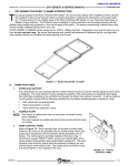
Installation and Operation Manual
TR5000 Series Transient Voltage Surge Suppressors
Model Types: TR5451 and TR5452
IMPORTANT NOTICE
THE ENTIRE CONTENT OF THIS INSTRUCTION MUST BE READ AND
FULLY UNDERSTOOD BEFORE ATTEMPTING ANY INSTALLATION
OR ENERGIZATION OF THE TVSS.
If the minimum requirements of this manual are not followed, the TVSS could become irreversibly damaged,
and/or the electrical system could be left unprotected. Failure to comply with the applicable requirements of
this instruction can void the TVSS warranty.
!
WARNING
SPECIAL ATTENTION MUST BE GIVEN TO VERIFY THAT A PROPER NEUTRAL-GROUND (XO) BOND
HAS BEEN MADE WHEN POWER IS SUPPLIED FROM AN UPSTREAM TRANSFORMER OR ANY OTHER
TYPE OF SEPARATELY DERIVED POWER SOURCE.
FAILURE TO PROVIDE THIS BOND, AS REQUIRED PER ARTICLE 250.30 OF THE NATIONAL ELECTRICAL
CODE, CAN RESULT IN ELEVATED PHASE TO GROUND SOURCE VOLTAGE POTENTIALS. THESE
VOLTAGES CAN CAUSE DAMAGE TO ELECTRICAL EQUIPMENT AS WELL AS SAFETY HAZARDS
INCLUDING FIRE, ELECTRICAL SHOCK, SERIOUS INJURY, OR DEATH.
THE EQUIPMENT COVERED BY THESE INSTRUCTIONS SHOULD BE INSTALLED AND SERVICED
ONLY BY COMPETENT PERSONNEL UTILIZING PROPER SAFETY PRACTICES AND PROCEDURES.
THESE INSTRUCTIONS ARE WRITTEN FOR SUCH PERSONNEL AND ARE NOT INTENDED AS A
SUBSTITUTE FOR ADEQUATE TRAINING AND EXPERIENCE IN SAFE PROCEDURES FOR THIS TYPE OF
EQUIPMENT.
POWER MUST BE PROVEN DISCONNECTED BEFORE STARTING INSTALLATION, INSPECTION OR
MAINTENANCE! FAILURE TO DO SO MAY CAUSE SERIOUS INJURY, DEATH AND/OR PROPERTY
DAMAGE.
PRODUCT DESCRIPTION:
GE TR5451 and TR5452 Model Transient Voltage Surge Suppressors (TVSS) are
designed for installation on low voltage electrical distribution systems, protecting electrical
equipment loads against the damaging effects of transient voltages.
PRE-INSTALLATION REQUIREMENTS:
Prior to installation of the TVSS, it is critical that the following items have been addressed.
DO NOT ATTEMPT TO CONTINUE WITH THE INSTALLATION IF ALL OF THESE CONDITIONS HAVE NOT
BEEN MET, OR ARE UNKNOWN.
Check the configuration and voltage supply ratings that will be feeding the TVSS
panel to ensure that the proper TVSS model number has been selected for your
2020003701 (08/06)
Page 1 of 4
PRE-INSTALLATION REQUIREMENTS (CONT.):
system. Refer to the “VOLTAGE RATINGS & POWER SOURCE
CONFIGURATIONS” chart below. The TVSS model number can be found on the
front of the unit.
Verify that an NEC (National Electrical Code) compliant X0 bond has been made at
the upstream transformer that feeds the electrical supply panel. Per NEC 250.30, this
bond must be in place on all grounded electrical systems.
The TR5451 or TR5452 model TVSS must be installed on a dedicated branch circuit
breaker. The maximum allowable rating for the circuit breaker is 30A / 22kAIC.
Do not attempt to install the TVSS on the upstream (line) side of the Main Breaker or
Fuse.
The TVSS should only be installed indoors in NEMA 1 type locations. Do not install
the TVSS outside or in wet locations.
VOLTAGE RATINGS & POWER SOURCE CONFIGURATIONS
MODEL
TYPE
NOMINAL
VOLTAGE
(50/60hZ)
MAXIMUM
CONTINOUS RMS
OPERATING
VOLTAGE
TR5451-120
ACT451-120
120V
150V (L-N / L-G)
SYSTEM
TYPE
SOURCE
CONFIGURATION
L1
Single Phase
2 Wire + Ground
ACT
451-240
TR5451-240
240V
270V (L-N / L-G)
ACT452-120
120 / 240V
150V (L-N / L-G)
TR5452-120
ACT452-120
120V
150V (L-N / L-G)
ACT452-240
240 / 480V
270V (L-N / L-G)
N
L1
Split Phase
3 Wire + Ground
N
L2
INSTALLATION:
POWER MUST BE PROVEN DISCONNECTED BEFORE
STARTING INSTALLATION, INSPECTION OR MAINTENANCE!
FAILURE TO DO SO MAY CAUSE SERIOUS INJURY, DEATH
AND/OR PROPERTY DAMAGE.
903-640-0555
800-950-2281
LISTED (48E6)
UL 1449, 2ND EDITION
FOR INDOOR USE ONLY
NOTE: If lamp is out, replace unit
Before attempting installation, make sure that the preinstallation requirements of this manual have been satisfied.
If the status of the pre-installation requirements are not
known, do not attempt to continue.
DUAL PHASE TVSS
120 VAC 50/60HZ
MOUNTING
SUPPRESSION VOLTAGES
330 L-N
600 L-L
TVSS
PART# ACT452120210N
DATE CODE: WO#
Spacer
Electrical
Panel
Threaded
Fitting
2020003701 (08/06)
1. TR5451 and TR5452 TVSS units are designed to be
mounted directly to the electrical panel through a ½”
knockout. Mounting feet are also supplied for instances
where direct connection to the panel is not practical. Select
a location that will allow the closest proximity to the breaker
that the TVSS will be connected to.
2. Use the ½” threaded fitting and spacer to secure the
TVSS to the Electrical Panel that is to be protected.
Page 2 of 4
INSTALLATION (CONT.):
Optional Alarm
Terminal
NO COM NC
903-640-0555
800-950-2281
LISTED (48E6)
UL 1449, 2ND EDITION
FOR INDOOR USE ONLY
3. The TVSS can be installed in any orientation, however
special consideration should be given to allow periodic
visual inspection of the status indicator lamps.
CONNECTION
NOTE: If lamp is out, replace unit
1. TR5451 and TR5452 Model TVSS units come equipped
with 10 AWG connection wires to allow termination to the
electrical system. It is important that the TVSS be installed
in a location that is as close to the termination point as
possible. Connection wires should be trimmed to prevent
excessive lead length. Do not coil, loop or make sharp
bends with the connection wires. Every inch of wire that
can be trimmed away will aid the TVSS in it’s ability to
provide the best possible protection level for your system.
DUAL PHASE TVSS
120 VAC 50/60HZ
SUPPRESSION VOLTAGES
330 L-N
600 L-L
TVSS
PART# ACT452120210N
DATE CODE: WO#
30 A. / 22kAIC
Max.
Black
White
Green
TR451 Wiring Diagram
Optional Alarm
Terminal
NO COM NC
903-640-0555
800-950-2281
LISTED (48E6)
UL 1449, 2ND EDITION
FOR INDOOR USE ONLY
NOTE: If lamp is out, replace unit
2. Refer to the wiring diagrams on the left for your selected
model type. The TR5451 and TR5452 models must be
connected to a branch circuit breaker. The breaker must
not exceed a 30A / 22kAIC rating.
3. Remote Alarm Relay Contacts are provided as an
optional feature on some model types. Contacts are
standard 1 Form C type, rated 5 A, 250 VAC max. Refer to
the wiring diagram on the left for contact configuration. The
relay contact will be closed between “NO” and “COM” under
normal operation. If the TVSS fails, or if power is lost to
the TVSS, the relay contact will open between “NO” and
“COM” and close between “NC” and “COM”.
4. Model types with 210N and 210S part number suffixes
are fitted with jumpers on the alarm terminal block which
connects the “COM” and “NC” contacts to the ground
terminal of the TVSS. This feature should only be utilized
for OEM installations where this type of configuration has
been evaluated as suitable. For all other installations, the
jumpers should be removed so that the alarm contacts will
function normally per paragraph 3 above.
OPERATION
DUAL PHASE TVSS
120 VAC 50/60HZ
SUPPRESSION VOLTAGES
330 L-N
600 L-L
TVSS
PART# ACT452120210N
DATE CODE: WO#
30 A. / 22kAIC
Max.
Black
1. When energized, the green LED status indicator lamps
located on the front of the TVSS will be illuminated. For
TR5451 models, there is 1 indicator. For TR5452 models,
there are 2.
2. If one or both of the of the status indicators are not
illuminated, verify the integrity of the connection
terminations, breaker status, the electrical supply voltage
and the electrical system grounding.
3. If no problems are found, the TVSS could be in failure
mode and require replacement. Contact your local GE
representative for further assistance.
White
MAINTENANCE
1. TR5451 and TR5452 model types contain no user
Black
Green
serviceable parts and require no annual maintenance or
calibration. Only a periodic visual inspection of the LED
indicators is required. Do not attempt to repair or otherwise
alter the TVSS unit.
TR452 Wiring Diagram
2020003701 (08/06)
Page 3 of 4
DIMENSIONS:
5.28
4.63
2.29
0.56
2.85
2.85
g
903-640-0555
800-950-2281
LISTED (48E6)
UL 1449, 2ND EDITION
FOR INDOOR USE ONLY
LISTED (48E6)
UL 1449, 2ND EDITION
FOR INDOOR USE ONLY
4.54
NOTE: If lamp is out, replace unit
NOTE: If lamp is out, replace unit
DUAL PHASE TVSS
DUAL PHASE TVSS
120 VAC 50/60HZ
120 VAC 50/60HZ
SUPPRESSION VOLTAGES
SUPPRESSION VOLTAGES
330 L-N
600 L-L
330 L-N
600 L-L
TVSS
PART# ACT452120210N
DATE CODE: WO#
TVSS
PART# ACT452120210N
DATE CODE: WO#
NO COM NC
STANDARD MODEL
903-640-0555
800-950-2281
210N / 210S MODEL TYPE
GENERAL SPECIFICATIONS:
Max. Surge Rating
40kA /Phase
TVSS Type
One Port / Parallel Connected
Connection Method
10 AWG Conductors
Operating Frequency
50Hz – 60Hz
Operating Temperature
-40o C to +70o C
Installation Location
Indoor / NEMA 1
Status Indication
Green LED Lamps / 1 per phase
Fusing
Thermally Protected MOV’s
Circuit Breaker
Required, 30A / 22kAIC Max. Rating
Regulatory
UL, cUL, CE
CERTIFICATE OF COMPLIANCE:
GE Zenith Controls hereby certifies that all TVSS products are manufactured in
accordance with the applicable drawing, specification and purchase order requirements in
compliance with the ISO 9001 Standard. Manufacturing Level Tests are performed on
100% of all units shipped. Verification Level Tests were also conducted on each product
family as part of the design verification process and was used to demonstrate that GE
Zenith has achieved the published design specifications . A certificate of compliance is
available upon request.
NOTICE:
These instructions do not purport to cover all details or variations in equipment nor to
provide for every possible contingency to be met in connection with installation, operation,
or maintenance. Should further information be desired or should particular problems arise
which are not covered sufficiently for the purchaser's purposes, the matter should be
referred to the GE Company.
GE DIGITAL ENERGY – GE Zenith Controls – 2501 Pecan Street – BONHAM, TEXAS 75418 USA
2020003701 (08/06)
Page 4 of 4