1
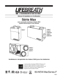
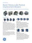
SPECIFICATIONS
ROOTS™ UNIVERSAL RAI-G®
Rotary Positive Gas Blowers
Frames 32 thru 615
BASIC BLOWER DESCRIPTION
Universal RAI-G® gas blowers are heavy duty rotary blowers
designed with mechanical seals and rugged steel mounting
feet. Optional feet are available for horizontal installations.
The compact, sturdy design is engineered for continuous
service when operated in accordance with speed and
pressure ratings.
The basic model consists of a cast iron casing, carburized
and ground alloy steel spur timing gears secured to steel
shafts with a taper mounting and locknut, and cast iron
involute impellers. Oversized anti-friction bearings are used,
with a cylindrical roller bearing at the drive shaft to withstand V-belt pull. The Universal RAI-G® features splash oil
lube on the gear end and grease lube on the drive end.
ROOT’s exclusive “figure-eight” gearbox design improves
oil distribution to maximize gear and bearing life.
Each unity is mechanically tested and given a 15 psig
static leak test. A 1/8” NPT purge port is provided at each
seal for buffer gas application as required. After testing, the
unit is sprayed with a protective paint, and boxed or skid
mounted for delivery.
Accessories are available through our distributors.
ROOTSTM Synthetic Oil and grease is recommended to
maintain warranty.
DESIGN AND CONSTRUCTION FEATURES
1.
2.
3.
4.
5.
6.
7.
8.
Mechanical seals
Rigid one-piece cast iron casing
Anti-friction bearings
Splash oil lubricated spur timing gears
Connections in standard pipe sizes
Straight, precision machined two-lobe impellers
Ground steel shafts
Detachable steel mounting feet
OPERATING PRINCIPLE
OUTLINE DRAWING & DIMENSIONAL TABLE
INLET & DISCHARGE CONNECTIONS
TOP DISCHARGE
P
C
P
M
AX
AX
TOP
SHAFT
O'
D1
O
D2
R
000
U -+001
D
BOTTOM DISCHARGE
A
LEFT DISCHARGE
RIGHT DISCHARGE
VERTICLE CONFIGURATION
Frame
32
33
36
42
45
47
53
56
59
65
68
615
A
7.25
7.25
7.25
8.00
8.00
8.00
10.50
10.50
10.50
11.00
11.00
11.00
A’
B
7.25
7.25
7.25
8.00
8.00
8.00
10.50
10.50
10.50
11.00
11.00
11.00
6.75
7.63
10.00
7.25
10.00
11.75
8.38
11.00
14.00
10.00
13.00
20.00
S-60A01 rev.0608
C
11.25
12.13
14.63
13.00
15.50
17.63
15.38
18.00
21.18
18.38
21.38
28.38
Two figure-eight lobe impellers mounted on parallel shafts rotate in
opposite directions. As each impeller passes the blower inlet, it traps
a definite volume of gas and carries it around the case to the blower
outlet, where the gas is discharged. With constant speed operation, the
displaced volume is essentially the same regardless
of pressure, temperature or barometric pressure.
A
BOTTOM
SHAFT
B
HORIZONTAL CONFIGURATION
D
D1
5.00
5.00
5.00
6.25
6.25
6.25
6.25
6.25
6.25
8.75
8.75
8.75
8.50
8.50
8.50
10.25
10.25
10.25
11.25
11.25
11.25
14.75
14.75
14.75
D2
M
O
O’
P
5.00 5.81 12.81 8.88 7.75
5.00 6.25 12.81 8.88 7.75
5.00 7.56 12.81 8.88 7.75
6.25 6.86 15.06 10.63 8.75
6.25 8.00 15.06 10.63 8.75
6.25 9.25 15.06 10.50 8.50
6.75 8.18 17.38 11.88 10.25
6.75 9.19 17.38 12.25 11.00
6.75 11.19 17.38 12.25 11.00
8.75 9.19 21.63 15.13 12.75
8.75 10.82 21.63 15.13 12.75
8.75 14.32 21.63 16.25 15.00
INLET
DISCH.
AX
12.13 6.75 .750 1.25 NPT
12.13 6.75 .750 2.0 NPT
12.13 6.75 .750 2.5 NPT
13.63 8.25 .875 1.5 NPT
13.63 8.25 .875 2.5 NPT
13.63 8.25 .875 3.0 NPT
17.25 8.75 1.125 .2.5 NPT
17.25 8.75 1.125 4.0 NPT
17.25 8.75 1.125 4.0 NPT
19.75 11.75 1.375 3.0 NPT
19.75 11.75 1.375 5.0 NPT
19.75 11.75 1.375 .6.0 FLG
1.75
1.75
1.75
2.00
2.00
2.00
2.50
2.50
2.50
3.00
3.00
3.00
P’
R
U
WGT
69
74
102
88
109
128
143
170
204
245
285
425
Timing gears control the relative position of the
impellers to each other and maintain small but
definite clearances. This allows operation without
lubrication being required inside the gas casing.
Dresser Roots
Houston, Texas Headquarters • U.S. Toll Free Phone: 1-877-363-ROOT(S) (7668) • Direct Phone: +1 832-590-2600
Connersville, Indiana Operations • U.S. Toll Free Phone: 1-877-442-7910 • Direct Phone: +1 765-827-9285
United Kingdom Operations • Phone: +44 (0) 1484 422 222
USA/Canada Sales • Phone: +1 773-444-3360
Houston, Texas Factory Service • Phone: +1 713-896-4810
Mexico City Sales and Factory Service • Phone: +52 55 5889 5811
Dubai Sales and Factory Service • Phone: +971 4-8830831
Malaysia Sales • Phone: +60 3 2163 0480
China Sales • Phone: +86 10 8486 2440
Shanghai Factory Service • Phone: +86 21 5858 7638
©2007 Dresser, Inc. all rights reserved. • Printed in the U.S.A. • All information subject to change
without notice. • Universal RAI and EasyAir are registered trademarks of Dresser, Inc. • ROOTS,
RAM X, and WHISPAIR, are trademarks of Dresser, Inc.
S-60A01 rev.0608
www.dresser.com
NOTES:
615U
68U
65U
59U
56U
53U
47U
45U
42U
36U
33U
41
95
122
58
132
169
109
231
292
64
136
172
136
281
354
183
375
470
92
168
313
164
292
536
259
447
802
190
333
481
305
535
772
572
1001
1445
1.7 37
3.0 91
3.7 118
2.4 54
4.1 128
5.0 165
3.9 102
6.8 224
8.3 286
2.4 59
4.1 132
5.1 168
4.7 129
8.2 274
10.1 346
6.2 174
10.8 366
13.3 461
3.4 86
5.2 163
9.1 308
5.7 155
8.7 283
15.0 527
8.4 248
12.8 436
22.0 791
6.4 181
9.9 324
13.9 471
10.3 291
15.7 520
21.8 757
19.1 544
29.1 973
40.0 1417
2.1
3.6
4.4
2.9
4.9
6.0
4.7
8.1
9.9
2.8
4.9
6.0
5.6
9.8
12.0
7.4
12.9
15.8
4.1
6.2
10.7
6.9
10.4
17.7
10.0
15.2
26.0
7.7
11.8
16.4
12.3
18.7
25.9
22.9
34.7
47.6
5 PSI
6 PSI
CFM BHP CFM BHP
34
88
115
49
123
160
96
218
279
56
128
165
122
267
340
166
357
453
81
157
302
147
275
518
238
425
780
172
315
463
277
506
743
519
948
1392
10.2
15.6
21.5
16.3
24.8
34.0
5.4
8.2
14.0
9.1
13.8
23.2
3.7
6.5
7.9
7.5
12.9
15.7
2.8
4.7
5.8
3.8
6.5
7.9
157
300
447
252
481
718
71
147
292
132
260
503
49
122
158
110
255
328
28
82
109
41
115
152
11.5
17.4
24.0
18.3
27.8
38.0
6.1
9.2
15.6
10.2
15.5
26.0
4.2
7.2
8.8
8.4
14.4
17.6
3.1
5.3
6.5
4.3
7.3
8.8
8 PSI
9 PSI
CFM BHP CFM BHP
2.4
31
4.2
85
5.1 112
3.3
45
5.7 119
6.9 1156
5.5
9.4
11.5
3.3
52
5.7 125
7.0 161
6.6 116
11.3 261
13.9 333
8.6
14.9
18.3
4.8
76
7.2 152
12.3 297
8.0 139
12.1 267
20.5 511
11.7
17.7
30.0
8.9 164
13.7 307
19.0 455
14.3 264
21.8 493
29.9 703
26.7
40.4
55.2
7 PSI
CFM BHP
150
293
426
241
470
707
66
143
288
125
253
496
46
119
155
104
249
322
25
79
106
38
112
149
12.7
19.3
26.5
20.3
30.8
42.1
6.8
10.3
17.2
11.4
17.2
28.7
4.7
8.0
9.8
9.3
16.0
19.5
3.5
5.9
7.2
4.7
8.1
9.8
10 PSI
CFM BHP
7.1
8.6
72
99
137
279
427
219
470
707
134
279
112
241
484
15.2
23.1
31.6
24.4
36.8
50.2
12.3
20.5
13.6
20.5
34.2
130
273
421
210
439
676
235
478
130
275
113 9.6 11.0
149 11.6 146
105 9.7
142 11.7
74
101
16.5
24.9
34.1
26.4
39.8
54.2
22.2
37.0
13.3
22.1
10.3
12.6
7.6
9.3
12 PSI
13 PSI
CFM BHP CFM BHP
1. Performance based on inlet methane at standard pressure of 14.7 psia, standard temperature of 68°F, and specific gravity of 0.55.
2. Vacuum ratings based on inlet methane at standard temperature of 68°F, discharge pressure of 30” Hg and specific gravity of 0.55.
1.4
2.4
3.0
1.9
3.3
4.1
3.2
5.5
6.7
1.9
3.3
4.1
3.8
6.7
8.2
5.0
8.8
10.9
2.7
4.2
7.4
4.6
7.0
12.2
6.7
10.3
18.0
5.2
8.0
11.4
8.3
12.7
17.8
15.4
23.2
32.4
45
99
126
64
138
174
116
238
300
68
141
177
144
289
362
193
385
480
99
175
320
174
302
546
272
459
815
201
343
491
322
551
788
603
1032
1476
32U
1750
2950
3550
1750
2950
3550
1750
2950
3550
1750
2950
3550
1750
2950
3550
1750
2950
3550
1170
1750
2850
1170
1750
2850
1170
1750
2850
1170
1750
2350
1170
1750
2350
1170
1750
2350
4 PSI
CFM BHP
Frame Speed
Size
RPM
PERFORMANCE TABLE: ROOTS Universal URAI-G
429
666
267
415
127
272
10.8
144
69
96
42.9
58.3
26.8
36.6
14.3
23.8
11.1
13.5
8.2
10.0
261
409
268
105
141
67
94
28.7
39.1
25.4
11.9
14.4
8.8
10.6
12
15
16
12
15
15
13
15
15
14
16
16
13
16
16
14
15
15
12
15
16
13
15
16
14
15
15
14
16
16
14
16
16
11
12
12
26
68
90
39
97
134
74
181
243
42
101
137
98
218
291
126
307
402
67
124
262
117
225
468
188
363
718
132
252
400
211
405
642
483
885
1329
2.0
4.3
5.6
2.8
5.9
7.2
5.0
9.8
11.9
3.0
6.2
7.6
5.9
12.5
15.2
8.4
15.4
18.8
4.3
7.5
13.4
7.2
12.6
21.0
11.4
18.4
30.8
8.7
15.1
20.6
13.9
24.0
32.8
20.5
33.7
46.0
14 PSI
15 PSI
VACUUM DATA
CFM BHP CFM BHP INHGV CFM BHP