1
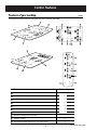
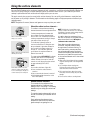
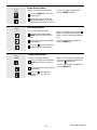
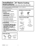
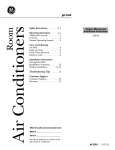
GE Consumer & Industrial
Technical Service Guide
January 2007
Profile
30- and 36-in.
Cooktops
PP945
PP975
GE
Profile
+
ON/OFF
+
POWER BOIL
ON/OFF
-
+
ON/OFF
+
ON/OFF
-
12 IN
9 IN
6 IN
HOT SURFACE
GE
+
ON/OFF
-
31-9149
GE Appliances
General Electric Company
Louisville, Kentucky 40225
+
-
+
WARMING ZONE
Profile
+
ON/OFF
12 IN
9 IN
6 IN
ON/OFF
+
ON/OFF
HOT SURFACE
CONTROL
LOCK
-
ON/OFF
CONTROL
LOCK
IMPORTANT SAFETY NOTICE
The information in this service guide is intended for use by
individuals possessing adequate backgrounds of electrical,
electronic, and mechanical experience. Any attempt to repair a
major ap pli ance may result in personal injury and property
damage. The manufacturer or seller cannot be responsible for the
interpretation of this information, nor can it assume any liability in
connection with its use.
WARNING
To avoid personal injury, disconnect power before servicing
this prod uct . If electrical power is required for diagnosis or test
purposes, disconnect the power immediately after performing the
necessary checks.
RECONNECT ALL GROUNDING DEVICES
If grounding wires, screws, straps, clips, nuts, or washers used to
complete a path to ground are removed for service, they must be
returned to their original position and properly fastened.
GE Consumer & Industrial
Technical Service Guide
Copyright © 2007
All rights reserved. This service guide may not be reproduced in whole or in part
in any form without written permission from the General Electric Company.
–2–
Table of Contents
Component Locator Views ...........................................................................................................................................13
Component Quick Reference Troubleshooting ...................................................................................................20
Control Features............................................................................................................................................................... 8
Cooktop Components .....................................................................................................................................................15
Cooktop Removal From Countertop ........................................................................................................................15
Daughter Relay Module (DRM)....................................................................................................................................16
Diagnostics and Service Information ......................................................................................................................20
Dimensions and Clearances ........................................................................................................................................ 7
Electrical Requirements ................................................................................................................................................. 6
Element Hot Light Troubleshooting .........................................................................................................................22
Element Resistance Troubleshooting ......................................................................................................................21
Glass Top .............................................................................................................................................................................15
Heating Elements ............................................................................................................................................................18
Installation .......................................................................................................................................................................... 6
Introduction ......................................................................................................................................................................... 5
Nomenclature .................................................................................................................................................................... 4
Operation Overview.........................................................................................................................................................12
Relay Power Supply Module (RPSM).........................................................................................................................17
Schematics and Wiring Diagrams ............................................................................................................................23
Warranty ..............................................................................................................................................................................27
–3–
Nomenclature
Model Number
P P 9 75 B M 1 BB
Product Color
B = Black
S = Black Glass W/Stainless Trim
W = White
Brand
P = Profile
Configuration
P = Cooktop
Engr. Revision
Model Year Designator
Feature Pack
Designates Features - the higher
the number, the more features
Mini Manual
Nomenclature Tag
The nomenclature tag of your cooktop
is located on the bottom of the burner
box. In addition to the model and serial
numbers, this tag tells you the power
ratings of the supply circuit for the
cooktop.
The mini-manual is located under the
glass top, inside the control enclosure.
Color Designator
Serial Number
The first two characters of the serial number
identify the month and year of manufacture.
Example:
AM123456S = January 2007
A - JAN
D - FEB
F - MAR
G - APR
H - MAY
L - JUN
M - JUL
R - AUG
S - SEP
T - OCT
V - NOV
Z - DEC
–4–
2007 - M
2006 - L
2005 - H
2004 - G
2003 - F
2002 - D
2001 - A
2000 - Z
1999 - V
1998 - T
1997 - S
1996 - R
The letter designating
the year repeats every
12 years.
Example:
T - 1974
T - 1986
T - 1998
Introduction
The new electronic cooktops make an eloquent statement of style, convenience, and kitchen planning
flexibility. The electronic touch controls are simple to understand and easy to operate–just read and touch.
Model Number PP945
GE
Profile
+
ON/OFF
+
POWER BOIL
ON/OFF
-
+
ON/OFF
+
ON/OFF
-
12 IN
9 IN
6 IN
HOT SURFACE
CONTROL
LOCK
Model Number PP975
GE
+
ON/OFF
-
+
+
WARMING ZONE
Profile
+
ON/OFF
12 IN
9 IN
6 IN
+
ON/OFF
-
ON/OFF
-
HOT SURFACE
CONTROL
LOCK
ON/OFF
-
These cooktops include many helpful features:
•
The controls lockout feature protects against power activation to a heating element during times of
unintended usage or when cleaning the cooktop.
•
The new warming feature keeps sauces and gravies warm (Model PP975).
The information on the following pages will help you service these new electronic cooktops effectively and
efficiently.
–5–
Installation
Electrical Requirements
GROUNDING SPECIFICATIONS
Ground Path Resistance 0.10 Ω Max.
Insulation Resistance 250K Ω Min.
POWER SUPPLY REQUIREMENTS
The cooktop must be connected to a supply circuit
of the proper voltage and frequency as specified
on the nomenclature tag. Wire size must conform
to the National Electrical Code or the prevailing
local code. The nomenclature tag is located on the
bottom of the burner box.
WIRING
Built-in power leads are UL approved for connection
to larger gauge household wiring. The insulation of
these leads is rated at temperatures much higher
than the temperature rating of household wiring.
The current carrying capacity of a conductor is
governed by the temperature rating of the insulation
around the wire rather than the wire gauge alone.
WARNING: Improper connection of aluminum house
wiring to these copper leads can result in a serious
problem. Use only connectors designed for joining
copper to aluminum and follow the manufacturer’s
recommended procedure closely.
OVERCURRENT PROTECTION
WIRING REQUIREMENTS
Wall-Mounted Oven or Counter-Mounted Cooktops
WARNING: This appliance must be properly
grounded.
NEC RATING
20 Amp
30 Amp
35 Amp
40 Amp
50 Amp
MAXIMUM KILOWATT RATING
208V
236V
240V
4.2
4.7
4.8
6.2
7.1
7.2
7.3
8.3
8.4
8.3
9.4
9.6
10.4
11.8
12.0
The branch circuit load for 1 wall-mounted oven
or 1 counter-mounted cooktop is the rating on the
nomenclature tag of the appliance.
The branch circuit load for a counter-mounted
cooktop and not more than 2 wall-mounted ovens―
all supplied from a single branch circuit and located
in the same room―shall be computed by adding the
nameplate ratings on the individual appliances and
treating this total as equivalent to 1 range.
All cooktops must be hard wired (direct wired)
into an approved junction box. The junction box
must be easily reached through the front of the
cabinet where the cooktop will be located. Allow
considerable slack in the conduit for serviceability.
A “plug and receptacle” is not permitted on these
products.
You must use a 2-wire, 3-conductor, 208/240 VAC,
60 Hertz electrical system. A white (neutral) wire
is not needed for this unit. The cooktop must be
installed in a circuit that does not exceed 125 VAC
nominal to ground.
Refer to the nomenclature tag on your cooktop for
the KW rating for your cooktop.
–6–
There must be 5 inches minimum vertical clearance
between the cooktop bottom and any combustible
surfaces.
Dimensions and Clearances
The following MINIMUM clearance dimensions must
be maintained.
13″ MAX. Depth of uprotected
overhead cabinets
2″ MIN.
Clearance from
cutout to side
wall on the right
of the unit
30″ MIN.
Clearance from
countertop to
unprotected
overhead
surface
5″ Min.
Vertical Clearance
15″ MIN. Height
from countertop
to nearest
cabinet on either
side of unit
2″ MIN. Clearance
from cutout to
side wall on the
left of the unit
Make sure the wall coverings, countertop and
cabinets around the cooktop can withstand heat up
to 200°F (93°C) generated by the cooktop.
If a 30-inch clearance between the cooking
surface and overhead combustible materials or
metal cabinets cannot be maintained, a minimum
clearance of 24 inches is required and the
underside of the cabinets above the cooktop must
be protected with not less than ¼-in. insulating
millboard covered with sheet metal not less than
0.0122 inches thick.
W all covering,
cabinets and
countertop must
withstand heat
up to 200°F ( 93° C ).
Overall Cooktop Dimensions - 36-in. Models
36″
(36-1/8″ SS)
20-7/8″ (21″ SS)
Depth on Monogram ZEU36K
is 21-1/4″ @ center.
Cooktop
33-3/4″
18-7/8″
3-1/4″ Front
4-5/8″ Rear
at the conduit
location
6-1/4″ Rear
on Model PP975
& PP980
Note: The junction box must be located where
it will allow considerable slack in the conduit for
serviceability.
Overall Cooktop Dimensions - 30-in. Models
29-3/4″
(29-7/8″ SS)
21-3/8″ (21-1/2″ SS)
Cooktop
18-7/8″
16″
Min.
33-3/4″
3-1/4″ Front
4-5/8″ Rear
at the conduit
location
6-1/4″ Rear
on Model PP945
& PP950
–7–
Install junction box so
that it can be reached
through the front of
the cabinet.
Control Features
Features of your cooktop.
ge.com
Throughout this manual, features and appearance may vary from your model.
WARMING ZONE
ON/OFF
ON/OFF
PP975
ON/OFF
W
AR
M
IN
G
ZO
N
O E
N
/O
FF
12IN
12
N
9I
N
LO TR
CK OL
O
6I
N
N
/O
FF
IN
O
N
/O
FF
9IN
O
N
/O
FF
H
O
T
SU
O
N
RF
AC
/O
E
FF
CO
6IN
ON/OFF
ON/OFF
CONTROL
LOCK
HOT SURFACE
ON/OFF
PP945
ON/OFF
ON/OFF
ON/OFF
12IN
9IN
6IN
HOT SURFACE
Feature Index (Features and appearances may vary.)
Explained on page
Single Surface Element
10
7
Dual Surface Element
10
7
Tri-Ring Surface Element
10
7
Warming Zone Surface Element
11
8
Single Surface Element Control Pad
10
7
Dual Surface Element Control Pad
7
10
Tri-Ring Surface Element Control Pad
7
10
Warming Zone Element Control Pad
11
8
Control Lock Pad
11
9
Hot Surface Indicator Lights (one for each surface element)
7,98
–8–
CONTROL
LOCK
5
(Continued next page)
Using the surface elements.
Your new Profile Cooktop makes an eloquent statement of style, convenience, and kitchen planning flexibility. Whether you
chose it for its purity of design, assiduous attention to detail, or for both of these reasons—you’ll find that your Profile
cooktop’s superior blend of form and function will delight you for years to come.
The touch controls give you precise control of the surface elements. You can quickly switch between a steady low heat
and full power or any setting in between. The information on the following pages will help you operate and maintain your
cooktop properly.
NOTE: Throughout this manual, features and appearance may vary from your model.
About the radiant surface elements…
SURFACE
COOKING
Never cook directly on the glass.
Always use cookware.
OFF CENTER
Always center the pan on the surface
element you are using.
DRAGGING
Do not slide cookware across the
control or cooktop surface because
it can scratch the glass. The glass is
scratch-resistant, not scratchproof.
The radiant cooktop features heating
elements beneath a smooth glass surface.
Cooktop temperatures increase with
the number of surface elements that
are on. With 3 or 4 elements turned on,
cooktop temperatures are high. Always
use caution when touching it.
The indicator lights will come on
next to the Dual and Tri-Ring burners
when activated. Lights also activate for
the Control Lock feature when it is
turned on. The indicator lights will
go off when the surface element or
feature is turned off.
The appropriate HOT SURFACE indicator
light will glow when its corresponding
radiant element is turned on and will
remain on until the surface has cooled
to approximately 150°F. (66°C).
NOTE:
Hot surface indicator light will:
■ Come on when the surface element is
turned on.
■ Stay on even after the element is turned off.
■ Glow brightly until the element has cooled
below 150°F. (66°C).
NOTE: A slight odor is normal when a new
cooktop is used for the first time. It is caused by
the heating of new parts and insulating materials
and will disappear in a short time.
It is safe to place hot cookware (from
the oven or surface) on the glass cooktop
when the surface is cool. Never place
cookware on the control area.
Even after the surface elements are
turned off, the glass cooktop retains
enough heat to continue cooking. To
avoid overcooking, remove pans from
the surface elements when the food is
cooked. Avoid placing utensils that could
become hot or plastics that could melt
on the surface element until it has cooled
completely.
■ Water stains (mineral deposits) are removable
using the cleaning cream or full strength white
vinegar.
■ Use of window cleaner may leave an
iridescent film on the cooktop. The cleaning
cream will remove this discoloration.
■ Don’t store heavy items above the cooktop.
If they drop onto the cooktop, they can cause
damage.
■ Do not use the surface as a cutting board.
Radiant Surface Elements
The controls for the radiant surface
elements allow for 11 different heat
settings: Low, 1–9 and High. The heating
element may not visibly glow at low heat
settings.
The surface heating element will cycle on
and off to maintain your selected control
setting.
Each radiant surface element has a
temperature limiter which protects the
glass cooktop from getting too hot.
–9–
(Continued next page)
ON/OFF
Single Surface Element
To turn on a single surface element:
Touch the ON/OFF pad, then touch
the (+)/(-) pad.
To turn off a single surface element,
touch the ON/OFF pad again.
Use the (+)/(-) pad to choose the
desired power setting. The control
will beep each time a pad is touched.
ON/OFF
Dual Surface Element
To turn on the surface elements:
Touch the dual surface element
ON/OFF pad, then touch the (+)/(-)
pad.
When the indicator light next to the
pad is on, the large surface element is on.
When it is off, the small surface element
is on.
Use the (+)/(-) pad to set the desired
power setting.
To turn the dual surface element off,
touch the ON/OFF pad.
Touch the
pad once to alternate
between large and small settings.
ON/OFF
Tri-Ring Surface Element
To turn on the surface elements:
Touch the Tri-Ring surface element
ON/OFF pad, then touch the (+)/(-)
pad.
Use the (+)/(-) pad to set the desired
power setting.
When one of the three surface elements
is on, the corresponding indicator light
next to the pad will be lit.
To turn the Tri-Ring surface element off,
touch the ON/OFF pad.
Touch the pad to alternate
between 12 in., 9 in. and 6 in.
settings.
– 10 –
(Continued next page)
Using the surface elements.
ON/OFF
Warming Zone Surface Element (on some models)
To turn on the warming zone surface
element:
Touch the warming zone ON/OFF
pad, then touch the (+)/(-) pad.
Use the (+)/(-) pad to choose a
setting of H (High) or L (Low).
To turn off the warming zone surface
element, touch the ON/OFF pad.
Use only cookware recommended for top-of-range
cooking.
The WARMING ZONE will keep hot,
cooked food at serving temperature.
Always start with hot food. Do not use to
heat cold food. Placing uncooked or cold
food on the warming zone could result in
foodborne illness.
For best results, all food on the
Error During Operation
If an error occurs in the control
operation, the cooktop operation will
discontinue and the unit will shut
down completely.
To correct:
Attempt to set the control to the
desired cooking setting.
Allow the cooktop to cool
completely.
If the cooktop will not operate, turn
off the cooktop power at the circuit
breaker or fuse box for one minute.
After one minute, turn on the
cooktop power at the breaker and
again attempt to set the control to
the desired cooking setting.
If the cooktop fails to operate, call
for service.
After the cooktop cools, attempt to
set the control to the desired
cooking setting.
CONTROL
LOCK
ErrortoDuring
Operation
How
Lock the
Cooktop
If an error occurs in the control
IMPORTANT:
As acooktop
convenience,
you will
operation, the
operation
can
lock
the
entire
cooktop
at
any
time
discontinue and the unit will shut
when it is not in use or before cleaning.
down completely.
Locking the cooktop will prevent surface
elements
from being turned on
To correct:
accidentally.
Attempt to set the control to the
To lock
the cooktop:
desired
cooking setting.
Touch
and
hold
the CONTROL
Allow the cooktop
to cool LOCK pad
for 3completely.
seconds.
A three-beep signal will sound and
After the
cooktop
attempt
the Control
Lock
light cools,
will turn
on, to
set the control to the desired
cooking setting.
– 11 –
If the cooktop will not operate, turn
indicating that the cooktop is locked.
off the cooktop power at the circuit
If the cooktop is locked while the surface
breaker or fuse box for one minute.
elements or timer are in use, they will
automatically
off. turn on the
After one turn
minute,
cooktop power at the breaker and
To unlock:
again attempt to set the control to
Touch
holdcooking
the CONTROL
theand
desired
setting.LOCK pad
again for 3 seconds.
If the cooktop
operate,
A three-beep
signalfails
willto
sound,
andcall
the
for service.
Control
Lock light will go out, indicating
that the cooktop is unlocked.
(Continued next page)
Operation Overview
DIGITAL CONTROL SYSTEM
The digital control system consists of 3 circuit boards:
1. The touch board (permanently adhered to the ceramic glass panel) senses user input, including control
lockout, displays user settings, contains HOT lights and key touch beeper. It is the “Main” board for the
system.
2. The relay power supply module (RPSM), located inside the drop box, provides DC for touch board
communications and to relays controlling the heating elements.
3. The daughter relay module (DRM) with additional relays is located under the touch board. The touch
board communicates with the RPSM board via 12-volt serial bus. The RPSM communicates with the DRM
via individual 5-volt and 12-volt DC levels.
There are no electronic sensors. Traditional-style sensors are located in the radiant elements providing overtemperature protection cycling and HOT lamp input to the RPSM board.
ELEMENT CONTROL
Each element is controlled by at least 2 relays. Both L1 and L2 are disconnected from the radiant elements
during standby (except the HOT lamp limiter switch). The setup relays remain constantly energized during
burner use. The cycle relays provide the duty cycling during non-HI settings. When non-Hi levels are
selected, the burners’ cycle relay will cycle 3 times per minute. When higher levels are selected, some cycling
of the element will occur due to the overtemperature limiter in the radiant element, which is in series with the
relays.
BURNER TOUCH KEYS
In standby, only the ON/OFF keys (and LOCK key) should respond. The +, –, and pan-size keys should not
respond until after the ON/OFF key has been touched first.
HOT LIGHT CHECK
The HOT lights are LEDs within the touch board. They are commanded "on" via serial bus responses from the
RPSM board to the touch board.
A HOT light glows from two sources:
1. Whenever a burner is activated, the HOT light is immediately on.
2. When the temperature of a ribbon heating element exceeds 150°F (66°C), the HOT light is on. At
temperatures over 150°F (66°C), the element's limiter switch closes, sending 240 VAC to the RPSM input at
J21 and initiating the serial bus response.
When the burner is cool to the touch and in standby, the HOT light should be off. When the burner is first
activated, HOT should glow immediately. If a burner has been on for approximately 1 minute (5 minutes for
model JP975), then returned to standby, the HOT light should remain on until cool.
Note: Due to the low wattage rating, the warming zone surface element (JP975) will not glow red even when
on highest heat setting. The warming zone surface element (JP975) does not utilize an overtemperature
limiter switch.
DEMO MODE
When 120 VAC is applied to the unit between the black and red leads, the touch board will operate normally,
but the relays and elements are prevented from operating.
– 12 –
Component Locator Views
Front View (Model PP945)
Glass Top With Permanently Attached Touch Board
Burner Box
Relay Power Supply Module Drop Box
Relay Power Supply Module (RPSM)
Top View - Glass Top Removed
Single Surface Element
Dual Surface Element
Daughter Relay Module
Single Surface Element
Tri-Ring Surface Element
– 13 –
(Continued next page)
Front View (Model 975PP)
Glass Top With Permanently Attached Touch Board
Burner Box
Relay Power Supply Module Drop Box
Relay Power Supply Module (RPSM)
Top View - Glass Top Removed
Tri-Ring Surface Element
Single Surface Element
Dual Surface Element
Daughter Relay Module
– 14 –
Warming Zone Surface Element
Dual Surface Element
Cooktop Components
WARNING: Before servicing the cooktop, power
must be removed from the cooktop by turning the
power off at the circuit breaker.
WARNING: Sharp edges may be exposed when
servicing. Use caution to avoid injury. Wear Kevlar
gloves or equivalent protection.
Glass Top
Note: The ceramic glass top and touch board will
be supplied as a complete assembly. If the touch
board is damaged or defective, the entire glass top
assembly must be replaced.
To replace the glass top:
Cooktop Removal From Countertop
To remove the cooktop from the countertop:
Caution: The hold-down brackets and screws
on the bottom of the burner box can damage
the countertop surface. Use care to protect the
countertop appearance.
Caution: To prevent electrostatic discharge that can
damage electronic controls, ground yourself to the
metal burner box or use an ESD wristband.
1. Remove the cooktop from the countertop. (See
Cooktop Removal From Countertop.)
2. Remove all screws along the top edge on all 4
sides of the burner box.
1. Remove screws that attach the hold-down
brackets to the inside of the cabinet.
Note: In the following step, it will be necessary to
utilize 2 strips of wood or cardboard.
2. Push upward on the bottom of the burner box
approximately 4 in. and rotate slightly left or
right (to the best working advantage). Shim
under the burner box with protective wood or
cardboard as shown.
3. Remove the mounting screw and hold-down
bracket from each side of the cooktop.
-
+
-
+
ON/OFF
-
ON/OFF
HOT SURFA
CE
LOCKCONTROL
+
6 IN 9 IN
-
ON/OFF
4. With the glass top tilted at an angle, disconnect
the wire harness that extends from the daughter
relay module (DRM) to the user interface by
pulling downward on the connector. Do not pull
on the wires.
Profile
12 IN
+
3. Slowly lift the front of the glass top (PP975),
or the right side of the glass top (PP945),
approximately 6 inches.
-
+
WARMING
ZONE
ON/OFF
ON/OFF
Mounting
Screw
Connector
Harness
Model PP975 Shown
5. Remove the glass top from the burner box. Place
the glass top on a protected surface.
– 15 –
Daughter Relay Module (DRM)
To replace the DRM:
1. Remove the glass top. (See Glass Top.)
2. Mark and disconnect wiring from the module.
Note: The module is held in place by 4 retainers
that lock the board in place using compression tabs.
It may be helpful to remove the ink tube from an
inexpensive ballpoint pen and place the barrel of the
pen over each retainer to compress the tab.
3. Compress the 4 tabs and lift the module from
the recess in the burner box.
Compression Tab
Retainer
Model PP975
Model PP945
– 16 –
Relay Power Supply Module (RPSM)
If the RPSM is damaged or defective, it can be
accessed by opening the drop box that is under the
cooktop.
Note: If the drop box is inaccessible, it will be
necessary to remove the cooktop from the
countertop. (See Cooktop Removal from Countertop.)
Place the cooktop upside down on a protected
surface.
Note: The module is held in place by 5 retainers
that lock the board in place using compression tabs.
It may be helpful to remove the ink tube from an
inexpensive ballpoint pen and place the barrel of
the pen over each retainer to compress the tab. (See
photo in Daughter Relay Module (DRM).)
4. Compress the 5 tabs and lift the module from
the drop box cover.
Caution:
To replace the RPSM:
•
When reinstalling the cover on the drop box,
ensure that the 2 insulating barriers are
positioned inside the drop box and against the
sides of the circuit board.
•
Make certain wiring is not pinched between the
cover and drop box.
1. Remove the five ¼-in. hex-head screws from the
drop box cover.
Insulating Barrier
2. Lift the cover up (or pull down if cooktop is
installed) and rotate it towards the rear of the
cooktop.
Insulating Barrier
Note: Make sure the 2 drop box cover tabs are
engaged in the drop box before replacing screws.
3. Mark and disconnect wiring from the module.
– 17 –
To remove heating elements:
Heating Elements
The radiant heating element consists of a ribbontype resistance wire attached to the support
insulation with molded ceramic walls in a corrosionprotected metal dish. On model PP975, the circular
heating elements come in 5 sizes.
1. Remove the glass top. (See Glass Top.)
2. Mark and remove the wires to the element.
3. Lift the element off the springs.
Note: When installing the new heating element,
make sure the 2 springs are on the 2 posts.
Post
Single Element
Dual Element
Spring
Dual Element
Tri-Ring Element
6-in. Warmer
On model PP945, the circular heating elements
come in 3 sizes.
Single Element
Dual Element
Tri-Ring Element
– 18 –
(Continued next page)
4. Mark the numbers on the bottom of the element
next to the tabs.
5. Remove the two ¼-in. hex-head screws and
tabs. Install them on the new element in the
same numbered position.
Tab
Mark Number
Mark Number
Tab
– 19 –
Diagnostics and Service Information
Component Quick Reference Troubleshooting
l
oo
sC t
las Ho
- G ss
e
p
tiv
On Gla
ys ve - art-u pera
ta
i
t S erat at St
Ino
igh
p
on
t L Ino ative lecti
r
Ho ght
e
i
pe in. S e
tL
no
v
i
I
Ho ght
r 6 erat tive
i
,o
a
p
r
o
tL
,9
e
12
op
Ho
t In
on
en
t In
cti
ing
-R Elem men lay
un
Tri
sF
e
sp
ing g El o Di -Key
-R
n
nt
Tri ri-Ri at-N
me
n T He Ele
No ents ny
m
nA
Ele at O ad
De
He
No tally
o
it T
Un
Supply Voltage
Wiring
RPSM
Touch Board
DRM
Element
DEAD UNIT: Turn off circuit breaker, wait 30 seconds, and turn circuit breaker on. Proceed to tests below.
DISPLAY CHECK: Turn burner on Level 8. All segments should light. Set 4 burners to 1, 2, 5, and 8. Check for
proper digit displays. When power is first applied, all the segments light in a sequence. Check for a consistent
pattern, none missing or doubled up.
VERSION DISPLAY: When the power is first applied, after the display test sequence, the 4-digit version
number of the touch board is momentarily shown in the display.
TOUCH KEYS IN GENERAL: Keys should respond to a grounded surface on the glass of 0.350-inch diameter,
which is the model for a finger. Keys should not respond to a grounded surface less than 0.130-inch
diameter. Water, etc., on the keys may cause them to not respond correctly because of unwanted ground
coupling. However, the OFF function will respond regardless of contamination. If the contamination is severe
enough to completely prevent touch key response, supervisory functions will turn off the burner. Removing
the contamination should restore proper key operation. After cleaning the keypad glass (ensure the keypad
is clean and dry), wait 30 - 60 seconds for keypad sensitivity to stabilize. A gap or moisture between the
touch board and glass will affect touch key performance. If this occurs, the glass assembly should be
replaced.
– 20 –
Element Resistance Troubleshooting
WARNING: The power must be disconnected from the cooktop.
The resistance of certain elements and the continuity of certain element circuit wiring can be tested without
removing the cooktop from its installation. This test will aid the service technician in determining if the RPSM
or the DRM should be replaced. This test assumes the touch board functions properly.
Model PP945
Component
Left Rear 1100W
Inner Element*
Left Rear 1300W
Outer Element*
Left Front 1200W
Element*
Right Front 1050W
Inner Element**
Right Front 900W
Center Element**
Right Front 1050W
Outer Element**
Right Rear 1200W
Element*
Ohms
50 Ω
Test Location
RPSM J2 to K7 Orange
43 Ω
RPSM J7-2 to K7 Orange
45 Ω
RPSM J7-12 to K10 Yellow
52 Ω
RPSM J7-1 to DRM K7 Blue
61 Ω
RPSM J7-3 to DRM K7 Blue
53 Ω
RPSM J7-4 to DRM K7 Blue
46.5 Ω
RPSM J7-8 to K14 Brown
Ohms
46 Ω
Test Location
RPSM J7-2 Orange/Black to K14 Orange
56.2 Ω
RPSM J7-4 Yellow/Black to K10 Yellow
46.2 Ω
RSPM J7-1 Yellow/Red to K10 Yellow
51.5 Ω
DRM J2 to K7 Gray
61.3 Ω
DRM J6-2 Gray/White to K7 Gray
52.3 Ω
DRM J6-6 Violet to K7 Gray
51.3 Ω
RPSM J7-8 Blue/White to K7 Blue
42.8 Ω
RPSM J2 to K7 Blue
0.5 Ω
RPSM J7-12 Brown to J7-3 Brown/White
Open Circuit Correction
Check Element and wiring.
Both OK - replace RPSM
Check Element and wiring.
Both OK - replace RPSM
Check Element and wiring.
Both OK - replace RPSM
Check Element and wiring.
Both OK - replace DRM
Check Element and wiring.
Both OK - replace DRM
Check Element and wiring.
Both OK - replace DRM
Check Element and wiring.
Both OK - replace RPSM
Model PP975
Component
Left Rear 1200W
Element*
Left Front 1000W
Inner Element*
Left Front 1200W
Outer Element*
Center 1050W
Inner Element**
Center 900W
Center Element**
Center 1050W
Outer Element**
Right Front 1100W
Inner Element*
Right Front 1300W
Outer Element*
Right Rear 120W
Element*
* Requires opening the drop box.
** Requires removing cooktop from it's installation and removing glass top.
– 21 –
Open Circuit Correction
Check Element and wiring.
Both OK - replace RPSM
Check Element and wiring.
Both OK - replace RPSM
Check Element and wiring.
Both OK - replace RPSM
Check Element and wiring.
Both OK - replace DRM
Check Element and wiring.
Both OK - replace DRM
Check Element and wiring.
Both OK - replace DRM
Check Element and wiring.
Both OK - replace RPSM
Check Element and wiring.
Both OK - replace RPSM
Check Element and wiring.
Both OK - replace RPSM
Element Hot Light Troubleshooting
Each element's hot light limiter switch and its wiring can be tested without removing the cooktop from its
installation. This test will aid the service technician in determining if the element should be replaced. This test
assumes the elements heat properly.
All circuits below element's glass top temperature of 150°F (66°C) should test open. If circuit tests 0
resistance, replace element.
All circuits above element's glass top temperature of 150°F (66°C) should test 0 resistance. If open, check
wiring and replace element, if necessary. Operate element, if necessary, then disconnect power before
testing cooktop.
Model PP 945
Left Rear Element*
Left Front Element*
Right Front Element*
Right Rear Element*
Test Location
RPSM J2 to J21-3
RPSM L1 to J21-2
RPSM L1 to J21-4
RPSM J2 to J21-1
Model PP 975
Left Rear Element*
Left Front Element*
Center Element*
Right Front Element*
Right Rear Element*
* Requires opening the drop box.
– 22 –
Test Location
RPSM L1 to J21-1
RPSM L1 to J21-2
RPSM L1 to J21-4
RPSM L1 to J21-3
RPSM L1 to J21-5
Schematics and Wiring Diagrams
Model PP945 - Element 240 VAC Schematic
WARNING: Disconnect electrical power before servicing.
Caution: Label all wires prior to disconnection. Wiring errors can cause improper and dangerous operation.
Verify operation after servicing.
– 23 –
(Continued next page)
WIRING DIAGRAM MODEL PP945
– 24 –
MODEL PP975 - ELEMENT 240 VAC SCHEMATIC
WARNING: Disconnect electrical power before servicing.
Caution: Label all wires prior to disconnection. Wiring errors can cause improper and dangerous operation.
Verify operation after servicing.
– 25 –
(Continued next page)
WIRING DIAGRAM MODEL PP975
– 26 –
Warranty
All warranty service provided by our Factory Service Centers,
or an authorized Customer Care® technician. To schedule
service, on-line, 24 hours a day, visit us at ge.com, or call
800.GE.CARES (800.432.2737). Please have serial number and
model number available when calling for service.
Staple your receipt here.
Proof of the original purchase
date is needed to obtain service
under the warranty.
For The Period Of:
GE Will Provide:
One Year
From the date of the
original purchase
Any part of the cooktop which fails due to a defect in materials or workmanship. During this
limited one-year warranty, GE will also provide, free of charge, all labor and in-home service
to replace the defective part.
Five Years
From the date of the
original purchase
A replacement glass cooktop if it should crack due to thermal shock, discolor, or
if the pattern wears off.
A replacement radiant surface element if it should burn out.
During this limited additional four-year warranty, you will be responsible for any labor or
in-home service.
What GE Will Not Cover:
■ Service trips to your home to teach you how to use
the product.
■ Replacement of house fuses or resetting of circuit
breakers.
■ Improper installation, delivery or maintenance.
■ Damage to the product caused by accident, fire, floods
or acts of God.
■ Failure of the product if it is abused, misused,
or used for other than the intended purpose or
used commercially.
■ Incidental or consequential damage caused by possible
defects with this appliance.
■ Damage to the glass cooktop caused by use of cleaners
other than the recommended cleaning creams and
pads.
■ Damage caused after delivery.
■ Product not accessible to provide required service.
■ Damage to the glass cooktop caused by hardened
spills of sugary materials or melted plastic that
are not cleaned according to the directions in
the Owner’s Manual.
EXCLUSION OF IMPLIED WARRANTIES—Your sole and exclusive remedy is product repair as provided in this Limited
Warranty. Any implied warranties, including the implied warranties of merchantability or fitness for a particular purpose,
are limited to one year or the shortest period allowed by law.
This warranty is extended to the original purchaser and any succeeding owner for products purchased for
home use within the USA. If the product is located in an area where service by a GE Authorized Servicer is not
available, you may be responsible for a trip charge or you may be required to bring the product to an Authorized GE
Service location for service. In Alaska, the warranty excludes the cost of shipping or service calls to your home.
Some states do not allow the exclusion or limitation of incidental or consequential damages. This warranty
gives you specific legal rights, and you may also have other rights which vary from state to state. To know
what your legal rights are, consult your local or state consumer affairs office or your state’s Attorney General.
Warrantor: General Electric Company. Louisville, KY 40225
– 27 –
19