1
GE
Lighting
Installation Guide
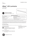
Albeo LED Luminaire
TM
Linear Lighting
(ALC3 Series)
BEFORE YOU BEGIN
Read these instructions completely and carefully.
WARNING/AVERTISSEMENT
RISK OF ELECTRIC SHOCK
• Turn power off before inspection, installation or removal.
• Properly ground electrical enclosure.
RISK OF FIRE
• Follow all NEC and local codes.
• Use only UL or IEC approved wire for input/output connections.
Minimum size 18 AWG.
RISQUES DE DÉCHARGES ÉLECTRIQUES
• Coupez l’alimentation avant d’’inspecter, installer ou déplacer le luminaire.
• Assurez-vous de correctement mettre à la terre le boîtier d’alimentation électrique.
RISQUES D’INCENDIE
• Respectez tous les codes NEC et codes locaux.
• N’utilisez que des fils approuvés par UL ou IEC pour les entrées/sorties de
connexion. Taille minimum 18 AWG.
This device complies with part 15 of the FCC Rules. Operation is subject to the following two conditions: (1) This device may not cause harmful interference, and
(2) this device must accept any interference received, including interference that may cause undesired operation. CAN ICES-3 (A)/NMB-3(A)
This equipment has been tested and found to comply with the limits for a Class A digital device, pursuant to part 15 of the FCC Rules. These limits are designed
to provide reasonable protection against harmful interference when the equipment is operated in a commercial environment. This equipment generates, uses,
and can radiate radio frequency energy and, if not installed and used in accordance with the instruction manual, may cause harmful interference to radio
communications. Operation of this equipment in a residential area is likely to cause harmful interference in which case the user will be required to correct the
interference at his own expense.
Save These Instructions
Use only in the manner intended by the manufacturer. If you have any questions, contact the manufacturer.
Prepare Electrical Wiring
Electrical Requirements
• The LED driver must be supplied with 120-277 VAC, 50/60
Hz per product label and connected to an individual properly
grounded branch circuit, protected by a 15 or 20 ampere
circuit breaker.
Grounding Instructions
• The grounding and bonding of the overall system shall be
done in accordance with National Electric Code (NEC) Article
600 and local codes.
imagination at work
Tools and Components Required
• ALC3 Series fixture
• Chain or cable (80 lbs. minimum load rated)
or RodMount kit
Cord Install:
• SJO or SJOW cable
• UL Listed strain relief(s)
(Hubbell SEC5O strain relief or
UL listed equivalent)
Conduit Install:
• 1/2” trade size flexible conduit
• 1/2” trade size conduit
Electrical Connections
1
Carefully unpack unit and properly inspect for defects
before installing. Wear work gloves to prevent dirt and
oil from being transferred to the luminaire.
A) Conduit
2
B) Power cord
For safety, turn off main power before installation of
fixture.
A) Conduit
B) Power cord
3
Option 1: power input from side. Remove knockout in
endcap and A) Install 1/2” conduit, or B) install AC power
cord with strain relief. Plug unused hole on top with
appropriate fitting.
4
Option 2: power input from top. A) Install 1/2” conduit,
or B) install AC power cord with strain relief.
5
Assuming Option 2 was chosen in previous step, remove
access panel to reach power supply wiring.
6
Connect the green (ground), black (line) and white
(neutral) wires of the AC line to the similarly colored
wires of the fixture’s power supply using UL listed
wire connectors. Re-attach access panel.
7
Restore main power.
Mounting Options
Please follow all UL, NEC and minimum load rating guidelines when selecting and installing a chain, cable or rod.
OPTION A Cable or Chain
1
Hang two chains/cables (rated to support a minimum load of 80 lbs.) from a structural member of the ceiling. Fixture must be
supported independently of an outlet box.
Attach to
structural member
2
Attach to
structural member
NOTE: When selecting chain, a joint in a
circular chain link shall be welded. A joint
in a chain link of another shape shall
not be located within 30 degrees of the
vertical unless welded.
Attach chain or cable to mounting holes on the end plates at both ends of the
fixture. Assure that the fixture is secure and cannot come free of mounting means.
OPTION B Rod Mount Kit
Materials Required:
• 3/8” threaded rod (Qty. 2)
• 3/8” nuts (Qty. 4)
• Rod Mount Kit
Attach to
structural member
Fasten
with nuts
1
Attach all rod mount brackets to fixture end plates
using screws and lock washers supplied in the Rod
Mount Kit.
GE Lighting • 1-888-MY-GE-LED
2
Secure 3/8” threaded rods into structural members in the
ceiling. Place a nut on each threaded rod where fixture
should hang. Slide fixture onto threaded rods, and place
second nut on to threaded rods to secure fixture in place.
Assure that the fixture is secure and cannot come free of
mounting means.
(1-888-69-43-533)
• www.gelighting.com
The GE brand, logo, and Albeo are trademarks of the General Electric Company.
© 2014 GE Lighting, LLC. Information provided is subject to change without notice. All values are design or typical values when measured under laboratory
conditions.
ALB008-030714