1
Gateway E-842R SAS RAID
USERGUIDE
®
Contents
Chapter 1: Introduction . . . . . . . . . . . . . . . . . . . . . . . . . . . . . . . . . . . . . . . . . . . 1
Overview . . . . . . . . . . . . . . . . . . . . . . . . . . . . . . . . . . . . . . . . . . . . . . . . . . . . . . . . . . . . . . . . . 2
Expansion enclosure . . . . . . . . . . . . . . . . . . . . . . . . . . . . . . . . . . . . . . . . . . . . . . . . . 2
The enclosure . . . . . . . . . . . . . . . . . . . . . . . . . . . . . . . . . . . . . . . . . . . . . . . . . . . . . . . . . . . . . 2
Enclosure chassis . . . . . . . . . . . . . . . . . . . . . . . . . . . . . . . . . . . . . . . . . . . . . . . . . . . . 3
Operator’s panel . . . . . . . . . . . . . . . . . . . . . . . . . . . . . . . . . . . . . . . . . . . . . . . . . . . . 4
Alarms . . . . . . . . . . . . . . . . . . . . . . . . . . . . . . . . . . . . . . . . . . . . . . . . . . . . . . . . . . . . . 4
The plug-in modules . . . . . . . . . . . . . . . . . . . . . . . . . . . . . . . . . . . . . . . . . . . . . . . . . . . . . . . 5
AC power supply module . . . . . . . . . . . . . . . . . . . . . . . . . . . . . . . . . . . . . . . . . . . . 5
Cooling module . . . . . . . . . . . . . . . . . . . . . . . . . . . . . . . . . . . . . . . . . . . . . . . . . . . . . 6
Controller module . . . . . . . . . . . . . . . . . . . . . . . . . . . . . . . . . . . . . . . . . . . . . . . . . . . 8
Battery module . . . . . . . . . . . . . . . . . . . . . . . . . . . . . . . . . . . . . . . . . . . . . . . . . . . . 10
Disk I/O module . . . . . . . . . . . . . . . . . . . . . . . . . . . . . . . . . . . . . . . . . . . . . . . . . . . 11
Drive carrier module . . . . . . . . . . . . . . . . . . . . . . . . . . . . . . . . . . . . . . . . . . . . . . . 12
Dummy carrier modules . . . . . . . . . . . . . . . . . . . . . . . . . . . . . . . . . . . . . . . . . . . . 13
Blank modules . . . . . . . . . . . . . . . . . . . . . . . . . . . . . . . . . . . . . . . . . . . . . . . . . . . . . 13
Chapter 2: Getting Started . . . . . . . . . . . . . . . . . . . . . . . . . . . . . . . . . . . . . . . 15
Introduction . . . . . . . . . . . . . . . . . . . . . . . . . . . . . . . . . . . . . . . . . . . . . . . . . . . . . . . . . . . . . . 16
Planning your installation . . . . . . . . . . . . . . . . . . . . . . . . . . . . . . . . . . . . . . . . . . . . . . . . . . 16
Enclosure drive bay numbering convention . . . . . . . . . . . . . . . . . . . . . . . . . . . 17
Drive carrier configuration . . . . . . . . . . . . . . . . . . . . . . . . . . . . . . . . . . . . . . . . . . 18
Enclosure installation procedures . . . . . . . . . . . . . . . . . . . . . . . . . . . . . . . . . . . . . . . . . . . 18
Preparing the site and host server . . . . . . . . . . . . . . . . . . . . . . . . . . . . . . . . . . . 18
Unpacking the enclosure system . . . . . . . . . . . . . . . . . . . . . . . . . . . . . . . . . . . . 18
Rack installation prerequisites . . . . . . . . . . . . . . . . . . . . . . . . . . . . . . . . . . . . . . . 19
Rack installation procedure . . . . . . . . . . . . . . . . . . . . . . . . . . . . . . . . . . . . . . . . . 20
Module installation . . . . . . . . . . . . . . . . . . . . . . . . . . . . . . . . . . . . . . . . . . . . . . . . . . . . . . . . 22
Enclosure configuration . . . . . . . . . . . . . . . . . . . . . . . . . . . . . . . . . . . . . . . . . . . . . . . . . . . 22
Enclosure cabling - single enclosure . . . . . . . . . . . . . . . . . . . . . . . . . . . . . . . . . . . . . . . . 22
Ethernet connection . . . . . . . . . . . . . . . . . . . . . . . . . . . . . . . . . . . . . . . . . . . . . . . . . . . . . . . 24
Enclosure cabling - multiple enclosures . . . . . . . . . . . . . . . . . . . . . . . . . . . . . . . . . . . . . 25
Drive slot arrangement . . . . . . . . . . . . . . . . . . . . . . . . . . . . . . . . . . . . . . . . . . . . . . . . . . . . 25
Drive location rules . . . . . . . . . . . . . . . . . . . . . . . . . . . . . . . . . . . . . . . . . . . . . . . . . 26
Power cord connection . . . . . . . . . . . . . . . . . . . . . . . . . . . . . . . . . . . . . . . . . . . . . . . . . . . . 28
Grounding checks . . . . . . . . . . . . . . . . . . . . . . . . . . . . . . . . . . . . . . . . . . . . . . . . . . . . . . . . . 28
Management interfaces . . . . . . . . . . . . . . . . . . . . . . . . . . . . . . . . . . . . . . . . . . . . . . . . . . . 29
StorView Storage Management software . . . . . . . . . . . . . . . . . . . . . . . . . . . . . 29
VDS . . . . . . . . . . . . . . . . . . . . . . . . . . . . . . . . . . . . . . . . . . . . . . . . . . . . . . . . . . . . . . . 29
Chapter 3: Operation . . . . . . . . . . . . . . . . . . . . . . . . . . . . . . . . . . . . . . . . . . . . 35
Before you begin . . . . . . . . . . . . . . . . . . . . . . . . . . . . . . . . . . . . . . . . . . . . . . . . . . . . . . . . . 36
Power on . . . . . . . . . . . . . . . . . . . . . . . . . . . . . . . . . . . . . . . . . . . . . . . . . . . . . . . . . . . . . . . . 36
Power supply module LEDs . . . . . . . . . . . . . . . . . . . . . . . . . . . . . . . . . . . . . . . . . 36
Ops panel LEDs . . . . . . . . . . . . . . . . . . . . . . . . . . . . . . . . . . . . . . . . . . . . . . . . . . . . 36
Controller module LEDs . . . . . . . . . . . . . . . . . . . . . . . . . . . . . . . . . . . . . . . . . . . . . 36
Cooling module LEDs . . . . . . . . . . . . . . . . . . . . . . . . . . . . . . . . . . . . . . . . . . . . . . . 36
iii
Contents
Disk I/O module LEDs . . . . . . . . . . . . . . . . . . . . . . . . . . . . . . . . . . . . . . . . . . . . . . .37
Starting the drives . . . . . . . . . . . . . . . . . . . . . . . . . . . . . . . . . . . . . . . . . . . . . . . . . . . . . . . .37
Disk drive LEDs . . . . . . . . . . . . . . . . . . . . . . . . . . . . . . . . . . . . . . . . . . . . . . . . . . . . .37
Starting StorView . . . . . . . . . . . . . . . . . . . . . . . . . . . . . . . . . . . . . . . . . . . . . . . . . . . . . . . . .37
Power down . . . . . . . . . . . . . . . . . . . . . . . . . . . . . . . . . . . . . . . . . . . . . . . . . . . . . . . . . . . . . .37
Chapter 4: Troubleshooting . . . . . . . . . . . . . . . . . . . . . . . . . . . . . . . . . . . . . . . 39
Overview . . . . . . . . . . . . . . . . . . . . . . . . . . . . . . . . . . . . . . . . . . . . . . . . . . . . . . . . . . . . . . . . .40
Initial start-up problems . . . . . . . . . . . . . . . . . . . . . . . . . . . . . . . . . . . . . . . . . . . .40
Status indicator LEDs . . . . . . . . . . . . . . . . . . . . . . . . . . . . . . . . . . . . . . . . . . . . . . . . . . . . . .41
Power supply module LEDs . . . . . . . . . . . . . . . . . . . . . . . . . . . . . . . . . . . . . . . . . .41
Cooling Module LED . . . . . . . . . . . . . . . . . . . . . . . . . . . . . . . . . . . . . . . . . . . . . . . .41
Ops panel LEDs . . . . . . . . . . . . . . . . . . . . . . . . . . . . . . . . . . . . . . . . . . . . . . . . . . . . .42
Controller module LEDs . . . . . . . . . . . . . . . . . . . . . . . . . . . . . . . . . . . . . . . . . . . . .43
Disk I/O module LEDs . . . . . . . . . . . . . . . . . . . . . . . . . . . . . . . . . . . . . . . . . . . . . . .43
Drive carrier LEDs . . . . . . . . . . . . . . . . . . . . . . . . . . . . . . . . . . . . . . . . . . . . . . . . . .43
Audible alarm . . . . . . . . . . . . . . . . . . . . . . . . . . . . . . . . . . . . . . . . . . . . . . . . . . . . . . . . . . . . .43
Audible alarm mute . . . . . . . . . . . . . . . . . . . . . . . . . . . . . . . . . . . . . . . . . . . . . . . .44
Drive carrier module faults . . . . . . . . . . . . . . . . . . . . . . . . . . . . . . . . . . . . . . . . . . . . . . . . .44
Auto start failure . . . . . . . . . . . . . . . . . . . . . . . . . . . . . . . . . . . . . . . . . . . . . . . . . . .44
Troubleshooting . . . . . . . . . . . . . . . . . . . . . . . . . . . . . . . . . . . . . . . . . . . . . . . . . . . . . . . . . .45
System faults . . . . . . . . . . . . . . . . . . . . . . . . . . . . . . . . . . . . . . . . . . . . . . . . . . . . . .45
Power supply faults . . . . . . . . . . . . . . . . . . . . . . . . . . . . . . . . . . . . . . . . . . . . . . . .45
Thermal control . . . . . . . . . . . . . . . . . . . . . . . . . . . . . . . . . . . . . . . . . . . . . . . . . . . .45
Thermal alarm . . . . . . . . . . . . . . . . . . . . . . . . . . . . . . . . . . . . . . . . . . . . . . . . . . . . .46
Thermal warnings . . . . . . . . . . . . . . . . . . . . . . . . . . . . . . . . . . . . . . . . . . . . . . . . . .46
Hardware faults . . . . . . . . . . . . . . . . . . . . . . . . . . . . . . . . . . . . . . . . . . . . . . . . . . . . . . . . . . .46
Continuous operation during replacement . . . . . . . . . . . . . . . . . . . . . . . . . . . . . . . . . . .47
Ops panel . . . . . . . . . . . . . . . . . . . . . . . . . . . . . . . . . . . . . . . . . . . . . . . . . . . . . . . . . .47
Replacing a module . . . . . . . . . . . . . . . . . . . . . . . . . . . . . . . . . . . . . . . . . . . . . . . . . . . . . . .47
Power supply modules . . . . . . . . . . . . . . . . . . . . . . . . . . . . . . . . . . . . . . . . . . . . . . . . . . . .47
AC Power supply module . . . . . . . . . . . . . . . . . . . . . . . . . . . . . . . . . . . . . . . . . . . .47
Cooling module . . . . . . . . . . . . . . . . . . . . . . . . . . . . . . . . . . . . . . . . . . . . . . . . . . . .49
Controller module . . . . . . . . . . . . . . . . . . . . . . . . . . . . . . . . . . . . . . . . . . . . . . . . . .50
Battery module . . . . . . . . . . . . . . . . . . . . . . . . . . . . . . . . . . . . . . . . . . . . . . . . . . . .52
Removing a battery module . . . . . . . . . . . . . . . . . . . . . . . . . . . . . . . . . . . . . . . . .53
Installing a battery module . . . . . . . . . . . . . . . . . . . . . . . . . . . . . . . . . . . . . . . . . .53
Removing and replacing a disk I/O module . . . . . . . . . . . . . . . . . . . . . . . . . . .53
Drive carrier module . . . . . . . . . . . . . . . . . . . . . . . . . . . . . . . . . . . . . . . . . . . . . . . . . . . . . .54
Removing a drive carrier module . . . . . . . . . . . . . . . . . . . . . . . . . . . . . . . . . . . .54
Installing a drive carrier module . . . . . . . . . . . . . . . . . . . . . . . . . . . . . . . . . . . . .55
Dummy drive carrier module removal and replacement . . . . . . . . . . . . . . . .56
Telephone support . . . . . . . . . . . . . . . . . . . . . . . . . . . . . . . . . . . . . . . . . . . . . . . . . . . . . . . .56
Appendix A: Specifications . . . . . . . . . . . . . . . . . . . . . . . . . . . . . . . . . . . . . . 57
Dimensions . . . . . . . . . . . . . . . . . . . . . . . . . . . . . . . . . . . . . . . . . . . . . . . . . . . . . . . . . . . . . . .58
Weight . . . . . . . . . . . . . . . . . . . . . . . . . . . . . . . . . . . . . . . . . . . . . . . . . . . . . . . . . . . . . . . . . . .58
iv
www.gateway.com
AC power (350 W power supply module) . . . . . . . . . . . . . . . . . . . . . . . . . . . . . . . . . . . . 58
Power consumption . . . . . . . . . . . . . . . . . . . . . . . . . . . . . . . . . . . . . . . . . . . . . . . . . . . . . . . 59
Power supply module safety and EMC compliance . . . . . . . . . . . . . . . . . . . . . . . . . . . 59
Environment . . . . . . . . . . . . . . . . . . . . . . . . . . . . . . . . . . . . . . . . . . . . . . . . . . . . . . . . . . . . . 59
Interfaces . . . . . . . . . . . . . . . . . . . . . . . . . . . . . . . . . . . . . . . . . . . . . . . . . . . . . . . . . . . . . . . . 60
Controller module specification . . . . . . . . . . . . . . . . . . . . . . . . . . . . . . . . . . . . . . . . . . . . 60
Disk I/O module specification . . . . . . . . . . . . . . . . . . . . . . . . . . . . . . . . . . . . . . . . . . . . . . 61
Drive carrier module specification . . . . . . . . . . . . . . . . . . . . . . . . . . . . . . . . . . . . . . . . . . 62
Appendix B: Legal Information. . . . . . . . . . . . . . . . . . . . . . . . . . . . . . . . . . . 63
Appendix C: Safety Information . . . . . . . . . . . . . . . . . . . . . . . . . . . . . . . . . . 67
v
Contents
vi
CHAPTER1
Introduction
• Overview
• The enclosure
• The plug-in modules
1
CHAPTER 1: Introduction
Overview
Important
Mixing of SAS and SATA drives in the same enclosure is only supported in columns,
for example, column 1 is all SAS and column 2 is all SATA. Also, mixing of drives of different
capacities in the same column is not supported.
The Gateway E-842R SAS Enclosure Platform is a 2U (rack space) disk drive enclosure, housing
twelve low profile (1-inch high), 3.5-inch form factor hard drives, which can be either:
• 3 GB direct dock SAS disk drives,
• 3 GB direct dock SATA disk drives, or
• 3 GB dual path SATA disk drives through an active/active SATA mux transition card.
The system provides as much as 6 TB of data storage per enclosure when 500 GB drives are
installed.
Expansion enclosure
RAID enclosure expansion is achieved by connecting expansion enclosures. Multiple enclosures are
connected together using SAS patch cables. You can connect as many as five enclosures. For more
information, see “Enclosure cabling - multiple enclosures” on page 25.
The enclosure
The Gateway E-842R design concept is based on an enclosure subsystem together with a set of
plug-in modules. The enclosure platform, as equipped, includes:
• Chassis and backplane with integrated (front panel mounted) operator’s panel.
• As many as 12 drive carrier modules, containing either:
• 3 GB direct dock SAS disk drives,
• 3 GB direct dock SATA disk drives, or
• 3 GB dual path SATA disk drives through an active/passive SATA mux transition card.
Important
Dummy carrier modules must be fitted in all unused drive bays to maintain
airflow. See “Dummy carrier modules” on page 13.
2
www.gateway.com
• Two plug-in power supply modules, 100-240 V AC, 350 W.
• One plug-in cooling fan module.
• Two plug-in controller modules, each incorporating a RAID controller and a StorView
Management Module.
Important
If only one controller module is installed, a blank module must be installed
in the unused slot.
Enclosure chassis
The chassis consists of a sheet metal enclosure assembly containing a backplane printed circuit
board (PCB) and module runner system.
• The chassis front panel incorporates an integrated operator’s (Ops) panel.
• The backplane PCB provides logic level signal and low voltage power distribution paths.
• The chassis has 19-inch rack mounting features so it fits into a standard 19-inch rack and
uses 2 EIA units of rack space (3.5” high).
Important
A drive bay is defined as the space required to house a single 1.0" high, 3.5inch disk drive in its carrier module.
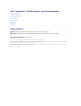
The chassis assembly contains 12 drive bays at the front, each of which accommodates the
appropriate plug-in drive carrier module. The 12 drive bays are arranged in 3 rows of 4 drives per
row. In the back, the chassis assembly contains five plug-in module bays to house two power supply
modules (PSUs), a cooling fan module, and two controller modules, which are installed horizontally
(one above the other) in the right bay.
0
1
0
1
PSU 1
PSU 2
Cooling Module
RAID Controller 0
RAID Controller 1
RAID enclosure (back)
FACTORY USE ONLY
FACTORY USE ONLY
PSU 1
PSU 2
Cooling Module
Disk I/O Module 0
Disk I/O Module 1
Expansion enclosure (back)
3
CHAPTER 1: Introduction
Operator’s panel
The enclosure’s front panel has an integrated operator’s (Ops) panel with four LEDs. The Ops panel
provides you with a high level indication of the operation of the enclosure. See “Ops panel LEDs”
on page 8 for details of the LED status conditions.
Caution
The Ops panel is an integral part of the enclosure assembly and cannot be replaced
separately. To replace the Ops panel, you must replace the entire enclosure.
Enclosure replacement should only be performed by trained personnel.
Alarms
Visible alarms
The functional modules have associated status LEDs. The Ops panel shows a consolidated status
for all modules. LEDs show constant green or blue to indicate good or positive status. Constant
or flashing orange LEDs indicate the presence of a fault within that module.
LED
State
Description
Power On
Constant green
Good or positive status
System Fault
Constant orange: fault present
Indicates a problem with a power supply, cooling, or
controller module. For more information, see the
tables in “Power supply module LEDs” on page 13,
“Cooling Module LED” on page 13, and “Controller
module LEDs” on page 15.
Logical Fault
Constant orange: fault present
Indicates failure of a drive module. The failing module
is indicated by the Fault LED. For more information,
see the table in “Drive carrier module faults” on
page 16.
Box Identity
Constant blue: enclosure identity
You can light this LED through the management
interfaces to indicate which enclosure requires
service actions.
See “Ops panel LEDs” on page 8 for a description of the Ops panel LED states.
4
www.gateway.com
Audible alarms
The Gateway E-842R enclosure includes an audible alarm which indicates when a fault state is
present. The following conditions activate the audible alarm:
• Fan fault
• Voltage out of range
• Over temperature
• Thermal overrun
• System fault
• Logical Fault
• Power supply module fault
When the audible alarm sounds, you can mute it by pressing the Alarm Mute button on the front
panel. For more information, see “Audible alarm mute” on page 16.
The plug-in modules
A Gateway E-842R enclosure requires the following modules for normal operation:
• Two 350 W AC power supply modules.
• One cooling module.
• One or two controller modules.
• As many as 12 drive carrier modules.
• Dummy drive carrier modules, as required.
Important
No drive bays should be left completely empty. Dummy carriers or blank modules
must be installed in all unused bays.
AC power supply module
Two, 100V-260 VAC 350 W power supply modules are supplied and mounted in the back of the
enclosure as part of the enclosure’s core product.
Power supply module input voltage operating ranges are nominally 115V or 230V AC, selected
automatically.
5
CHAPTER 1: Introduction
Two LEDs mounted on the rear panel of the power supply module indicate the status of the module:
Power On & OK
(Green)
Module Fault
(Orange)
Status
Off
Off
No AC power (either power supply module)
Off
On
No AC power (this power supply module only)
Power supply module fault (over temperature, over
voltage, over current, or power supply module fan fail)
On
Off
AC present, power supply module on and OK
On
On
Power supply module fan fault
Multiple power supply modules
In order to maintain the appropriate airflow, you must always operate the Gateway E-842R with
two power supply modules installed. The two power supply modules operate together so if one
fails, the other maintains the power supply and cooling while you replace the faulty module.
Module replacement should only take a few minutes to perform but must be completed within
10 minutes from removal of the failed module.
Cooling module
The cooling module provides system cooling, thermal monitoring, and control functions.
System airflow is from the front to the back of the enclosure:
• Cooling air passes over drives and through the midplane to a central air passage.
• The cooling module pulls air from the air passage and from the controller modules.
Important
The system must be operated with a low pressure rear exhaust installation
(back pressure created by rack doors and obstacles not to exceed 5 pascals (0.5 mm
water gauge)).
• The power supply modules pull cooling air from the air passage at the back of the enclosure.
6
www.gateway.com
The module has an orange Cooling Module Fault LED.
LED status is described in the following table:
Module Fault (Orange)
Status
Off
Enclosure Off - Indicated by power supply module and controller
module OK lights
Off
Enclosure On - Fan OK
On
Cooling module fan failure
7
CHAPTER 1: Introduction
Controller module
Caution
Operation of the enclosure with any modules missing disrupts the airflow and the
drives do not receive sufficient cooling. All openings must be filled before operating the
enclosure.
When only one controller module is installed, a blank module must be installed in the vacant
controller module slot at the rear of the enclosure to maintain airflow and ensure correct
operation.
Important
Do not mix Disk I/O modules and RAID Controller modules in the same enclosure. Disk
I/O modules are only installed in the expansion enclosure and RAID Controllers are only
installed in the RAID enclosure.
One or two controller modules (depending on your configuration) are supplied and mounted in
the back of the enclosure as part of the Gateway E-842R enclosure core product.
The plug-in controller modules have been designed for integration into the enclosure, providing
external FC cable interfacing with the host computer system.
The backplane incorporates a connection to each of the SAS ports within the controller modules.
The controller module’s internal processor monitors error conditions on each disk drive port.
Processors housed on the controller modules provide enclosure management interfacing to devices
on the backplane, power supply module, controller module, and Ops panel to monitor internal
functions. These processors operate in a dual active configuration to allow failover.
The module incorporates LED indicators. For the location of the LED indicators, see “Controller
module LEDs” on page 8.
External ports
The RAID controller module has the following external ports:
• Two external (host) SAS ports that allow for fitting of Small Form-Factor Pluggable (SFP)
modules, with auto-bypass at the output. Either or both of these SFP ports can be used to
provide connection to the host controllers. Each host port operates at 3 Gb/s, giving an
effective speed of 6 Gb/s. These ports are also backwards compatible with 2 Gb/s hosts.
• An SAS expansion port supports as many as four expansion enclosures through an SFF-8470
connector.
8
www.gateway.com
• An RJ45 10/100BaseT Ethernet port lets you connect the controller to a network to enable
out-of-band management and monitoring using the embedded StorView GUI software.
Important
Only shielded, Cat 5 (or better) cables should be used for connection to the
Ehternet port for EMC performance.
• There is also an RS232 socket which provides an alternative user interface to the RJ45
connector.
Caution
Although the RS232 port is similar in appearance to a USB port, it requires a
special cable and you should not attach a USB cable to it.
The recommended configurations are shown in “Ethernet connection” on page 24 and “Enclosure
cabling - multiple enclosures” on page 25.
StorView Management software
The StorView Storage Management software which is embedded in the controller module is a
full-featured, graphical, HTML-based software suite designed to configure, manage, and monitor
the controller module storage solution. The module is configured with a base IP address to let you
connect to it. See “StorView Storage Management software” on page 29 or the Gateway E-842R
StorView Storage Management Software User Guide for further information.
LED functions
LED state
Definition
Battery fault
Orange
When lit, this LED indicates that the backup
battery unit is missing, has low voltage, has
experienced a time-out on charge indicating a
faulty battery, or has experienced a fault in the
charging circuitry.
Cache active
Orange
When lit, this LED indicates that the RAID
controller cache has data saved in memory but
not written to the disk array.
Controller activity on drive
bank 0
Orange
When lit, this LED indicates activity on the Bank
0 disk drives.
Controller activity on drive
bank 1
Orange
When lit, this LED indicates activity on the Bank
1 disk drives.
9
CHAPTER 1: Introduction
Controller OK
Green
When lit, this LED indicates that RAID controller
activity is normal.
Controller fault
Orange
When lit, this LED indicates that a RAID
controller fault has occurred.
Ethernet status
Green
When lit, this LED indicates that the Ethernet
port has a valid connection.
Orange
When lit, this LED indicates that the Ethernet
port has activity.
Green
When lit, these LEDs show I/O activity on the
specific port lane indicated.
SAS activity
Battery module
Each controller module assembly includes a removable battery module (for the location, see
“Controller module” on page 8). The battery module contains a replaceable Li-Ion battery pack,
as shown in the following illustration. The battery pack protects the cache contents if the AC power
fails. You can check the amount of battery time available through the Management Interface. The
amount of time available is dependent on the amount of cache in the system.
See “Battery module” on page 24 for removal and replacement procedures.
10
www.gateway.com
Disk I/O module
The expansion enclosure houses one or two Disk I/O modules. They provide the drive expansion
for the RAID enclosure. When expanding the system, you may add up to four expansion enclosures.
This will give you a total of five enclosures including the RAID enclosure. A fully loaded system
will provide a total of 60 disk drives.
Important
Do not mix Disk I/O modules and RAID Controller modules in the same enclosure. Disk
I/O modules are only installed in the expansion enclosure and RAID Controllers are only
installed in the RAID enclosure.
Processors housed on the Disk I/O modules provide enclosure management and an interface to
the devices on the backplane, PSU, Disk I/O module and Ops panel, which monitor internal
functions. These Disk I/O module processors operate in a master-slave configuration to allow for
failover.
The enclosure may be configured with either one or two modules. If only one Disk I/O module is
installed, a blank module must be installed in the unused bay.
Each SAS connector has four LEDs adjacent to the connector. The LEDs indicate I/O activity on that
specific SAS port lane where each port has four lanes.
Important
The OUT port on the RAID Controller or DIsk I/O module connects to the IN port on
the Disk I/O module in the next E-842R enclosure in a multiple enclosure configuration, See
“Enclosure cabling - multiple enclosures” on page 25 for further information on enclosure
expansion.
11
CHAPTER 1: Introduction
Drive carrier module
The drive carrier module comprises a hard disk mounted in a carrier. Each drive bay houses a single,
low profile, 1.0-inch high, 3.5-inch form-factor disk drive in its carrier. The carrier has mounting
locations for SAS or SATA drives.
The front cap also supports an ergonomic handle which provides the following functions:
• Inserting the carriers into the drive bays
• Removing the carriers from drive bays
• Positive “spring loading” of the drive/backplane connector
• An anti-tamper lock operated by a torx-socket type key
Drive status indicators
Each drive carrier has two LEDs, an upper (green) and lower (orange). In normal operation the
green indicator is ON and flickers as the drive operates. The orange indicator is only ON if there
is a drive fault. If the green LED is OFF when the orange LED is ON, a power control circuit failure
is indicated.
Power On & OK
(Green)
Module Fault
(Orange)
Status
On
Off
Normal operation
On
On
Drive fault
Off
On
A power control circuit failure
Anti-tamper locks
Anti-tamper locks are installed in the drive carrier handles and are accessed through the small
cutout in the latch section of the handle. These locks are provided to disable the normal “pinch”
latch action of the carrier handle.
12
www.gateway.com
Dummy carrier modules
Dummy carrier modules are provided for fitting in all unused drive bays. They are designed as
integral drive module front caps and must be installed in all unused drive bays to maintain a
balanced airflow.
Blank modules
Caution
Operation of the enclosure with any modules missing disrupts the airflow and the
drives do not receive sufficient cooling. All openings must be filled before operating the
enclosure.
When only one controller module is installed, a blank module must be installed in the vacant
controller module slot at the rear of the enclosure to maintain airflow and ensure correct
operation.
Important
Do not mix Disk I/O modules and RAID Controller modules in the same enclosure. Disk
I/O modules are only installed in the expansion enclosure and RAID Controllers are only
installed in the RAID enclosure.
13
CHAPTER 1: Introduction
14
CHAPTER2
Getting Started
•
•
•
•
•
•
•
•
•
•
•
•
Introduction
Planning your installation
Enclosure installation procedures
Module installation
Enclosure configuration
Enclosure cabling - single enclosure
Ethernet connection
Enclosure cabling - multiple enclosures
Drive slot arrangement
Power cord connection
Grounding checks
Management interfaces
15
CHAPTER 2: Getting Started
Introduction
Caution
When connecting the enclosure, use only the power cords supplied or cords which
match the specification quoted in “Specifications” on page 29.
This chapter explains how to install your enclosure into an industry-standard, 19-inch rack cabinet
and configure the enclosure sub-system.
Planning your installation
Caution
Blank modules or dummy carrier modules MUST be installed in ALL unused bays or
the enclosure may overheat.
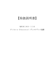
Before you begin installation, you should become familiar with the configuration requirements of
your enclosure, detailed in the following table. The correct positions of each of the optional plug-in
modules are shown in the illustration. See “Ethernet connection” on page 24 and “Enclosure cabling
- multiple enclosures” on page 25 for details of controller module configurations.
Module
Location
Drive bays
All drive bays must have a drive carrier module or dummy drive carrier module installed. No bays should
be left empty.
Power supply (PSU)
modules
Two power supply modules must be installed. Full power redundancy is provided while a faulty module
is replaced. Install the power supply modules in the left rear bays, as shown in the following illustration.
Cooling module
Install the cooling module in the rear bay, as shown in the following illustration.
Controller module
Two RAID controller modules (or one controller module and one blank module) can be installed,
depending on the configuration you require. The modules are installed horizontally (one above the
other) in the right rear bay.
Disk I/O module
Two Disk I/O modules (or one Disk I/O module and one blank module) can be installed, depending on
the configuration you require. The modules are installed horizontally (one above the other) in the right
rear bay.
0
1
0
1
PSU 1
PSU 2
Cooling Module
Enclosure module
16
RAID Controller 0
RAID Controller 1
www.gateway.com
FACTORY USE ONLY
FACTORY USE ONLY
PSU 1
PSU 2
Cooling Module
Disk I/O Module 0
Disk I/O Module 1
Disk I/O module
Enclosure drive bay numbering convention
Important
Drive carrier modules must always be installed in drive locations 1 and 12. This is the
minimum configuration required for the system to operate and provide SES Management
Services.
The enclosure drive bay numbering convention is shown in the illustration on page 16. A drive bay
is defined as the space required to house a single 1.0-inch high, 3.5-inch disk drive in its carrier
module.
Drive carrier configuration
Important
Before you begin installation, you should become familiar with the configuration
requirements of your enclosure. There must be a drive present in drive locations 1 and 12
to enable SES communications to operate. Installing drives in both of these bays provides
redundant SES communication paths.
When planning your system configuration, remember that all enclosure drive bays must be filled
with either a drive carrier or dummy drive carrier module. No bays should be left empty.
Enclosure installation procedures
Warning
An enclosure with all component parts installed is too heavy for a single person to
safely install alone into a rack cabinet.
The following procedures describe the installation of an enclosure and highlight any critical
requirements and good handling practices you should follow to ensure a successful installation.
Caution
Make sure that you wear a suitable anti-static wrist or ankle strap and observe all
conventional ESD precautions when handling modules and components. Avoid contact with
such things as backplane components and module connectors.
17
CHAPTER 2: Getting Started
Preparing the site and host server
Important
The E-842R system supports most of the widely used operating systems. However
deployment on Microsoft Windows requires the .inf driver file which is found on the Gateway
External Storage CD (ESCD). (For Windows Servers, insert the ESCD and install the .inf file.)
Before you begin, make sure that the site where you intend to set up and use your storage system
has the following:
• Standard AC power from an independent source or a rack power distribution unit with a
UPS (universal power supply).
• A host computer with a standard Fibre Channel HBA (host bus adapter) with the latest BIOS
and drivers. Follow the instructions provided with your HBA and install the HBA and its driver
software, if necessary.
Unpacking the enclosure system
The package contents and unpacking procedure are outlined in the following illustration.
The accessory box contains the AC power cord(s), a serial communication cord, and the software
and the Gateway External Storage CD (ESCD). The accessory box insert contains the adjustable rail
slides and hardware parts to rack mount the enclosure.
18
www.gateway.com
Rack installation prerequisites
The enclosure is designed for installation into an industry standard, 19-inch cabinet, capable of
holding the unit.
• A minimum depth of 28 inches (700 mm) from the front flange to the back metalwork
(excludes back cabling).
• Up to 70.5 lbs (32 kg) per enclosure, depending on configuration.
• A minimum gap of 1 inch (25 mm) of clearance between the rack cover and the front of the
drawer, and 2 inches (50 mm) of rear clearance between the back of the drawer and the
back of the rack is recommended, in order to maintain the correct airflow around the
enclosure.
• The rack should have a maximum back pressure of 5 pascals (0.5 mm water gauge).
Rack mounting rail kit
A set of mounting rails is available for use in 19-inch rack cabinets. These rails have been designed
and tested to handle the maximum enclosure weight and to ensure that multiple enclosures may
be installed without loss of space within the rack. Use of other mounting hardware may cause
some loss of rack space.
The rack mounting rail kit also incorporates a rear hold down mechanism to ensure shock and
vibration immunity.
Contact Gateway Customer Care to make sure that suitable mount rails are available for the rack
you are using.
Rack installation procedure
See the detail drawings supplied with the rack mounting rail kit for additional information.
Installation procedure
To install the rack mounting rail kit:
1 Attach left and right chassis slides to the enclosure sides using 8 M3x4 button head screws.
19
CHAPTER 2: Getting Started
2 Assemble the left and right chassis latches using the special chassis latch screws. Make sure
that the latch is orientated as shown in the following illustration, with the spring arm located
against its stop (on the right side at the top, on the left side at the bottom).
3 Assemble the rack brackets to the rack posts as follows:
a Fit the location pin at the back of the rail into the rear rail post.
b Extend the rail to fit between the front and rear rack posts.
c Attach the rail to both the front and rear of the rack using the washers and screws
supplied. The screws should be left loose enough to allow for sideways movement of
the rail.
d Tighten the two clamping screws located on the inside of the rear section of the rack
bracket.
Rear rack post
Clamping screws
Guide pin
Rack bracket
Guide pin
Slide washer
Phillips screw
Front rack post
Square hole rack
Remove the nut when you use
tapped hole rack posts.
20
Tapped hole rack
www.gateway.com
4
Mount the enclosure in the rack as follows:
a
b
c
d
Lift the enclosure and align it with the rack rails.
Carefully insert the chassis slides into the rack rails and push it fully into the cabinet.
Tighten the rear screws.
Withdraw the enclosure until it reaches the hard stops (approximately 15.75 inches
(400 mm)).
e Return the enclosure to the fully installed position and attach to the rack using the
captive thumbscrews on the front flanges.
Module installation
The enclosure comes fully populated with all plug-in modules installed. For information on removal
or replacement of plug-in modules, see “Troubleshooting” on page 11.
Enclosure configuration
Enclosures are configured with one internal domain of 12 drives per controller module.
Enclosure cabling - single enclosure
The RAID controller module provides bi-directional connection between the host-side interface and
the drives. The drives will not be presented to the Host until they are configured and mapped by
the controller.
21
CHAPTER 2: Getting Started
Each E-842R RAID controller module can be connected to up to two independent Host Bus Adaptors.
Some typical configurations utilizing one or two RAID controller modules and either one or two
HBAs are shown in the following.
Single host, single HBA, and single controller connection
Dual host, single HBA, and single controller connections
Single host, dual HBAs, and dual controller connections
22
www.gateway.com
Dual hosts, dual HBAs, and dual controller connections
Dual host, single HBA, and dual controller connections
Ethernet connection
Important
Only shielded Cat 5 (or better) cables should be used for connection to the Ethernet
port for EMC conformance.
An RJ-45 10/100BaseT Ethernet port lets you connect the controller to a network to enable out-of
-band management and monitoring using the Embedded StorView GUI software.
Make sure that the PC is connected either directly or through a switched LAN to the Ethernet.
23
CHAPTER 2: Getting Started
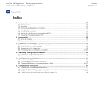
Enclosure cabling - multiple enclosures
You can connect additional expansion enclosures to an E-842R RAID enclosure. Multiple enclosures
are connected together using SAS patch cables, up to a maximum of five enclosures, including the
RAID enclosure. A typical two-expansion enclosure configuration is shown below. To fully populate
your installation to the maximum number of enclosures, follow the example below connecting the
enclosures in the same fashion for each additional expansion enclosure.
Drive slot arrangement
Each enclosure has 12 drives which are referenced by their locations as shown in the following
table. Drives are numbered column/row. For information on installing drive carrier modules, see
“Installing a drive carrier module” on page 27.
24
Column/row
1
2
3
4
1
Drive 1
Drive 2
Drive 3
Drive 4
2
Drive 5
Drive 6
Drive 7
Drive 8
3
Drive 9
Drive 10
Drive 11
Drive 12
www.gateway.com
Drive location rules
The E-842R storage enclosure supports two different types of disk drives, SAS and SATA. In order
to allow optimal configurations to be built, the following rules should be observed:
Different drive types cannot be mixed in the same column.
• Slots 1, 5, 9 = column 1
• Slots 2, 6, 10 = column 2
• Slots 3, 7, 11 = column 3
• Slots 4, 8, 12 = column 4
To achieve optimum performance, drives should be populated in the following sequence:
• Initially—Slots 2, 6, and 10
• Then—Slots 3, 7, and 11
• Then—Slots 1, 5, and 9
• Then—Slots 4, 8, and 12
Drive Location Sequence (1)
Column/row
1/#
2/#
3/#
4/#
#/1
-
2
-
-
#/2
-
6
-
-
#/3
-
10
-
-
Drive Location Sequence (2)
Column/row
1/#
2/#
3/#
4/#
#/1
-
2
3
-
#/2
-
6
7
-
#/3
-
10
11
-
Drive Location Sequence (3)
Column/row
1/#
2/#
3/#
4/#
#/1
1
2
3
-
#/2
5
6
7
-
#/3
9
10
11
-
Drive Location Sequence (4)
Column/row
1/#
2/#
3/#
4/#
#/1
1
2
3
4
#/2
5
6
7
8
#/3
9
10
11
12
25
CHAPTER 2: Getting Started
If you need to change drive technology, a new column of drives should be populated.
Column/row
1/#
2/#
3/#
4/#
#/1
-
SAS 2
SATA 3
-
#/2
-
SAS 6
SATA 7
-
#/3
-
-
SATA 11
-
All members of the column should have the same drive type.
Drive start
With two active power supply modules installed (required), all drives start immediately.
Activating the anti-tamper locks
The anti-tamper locks are installed in the drive carrier handles and are accessed through the small
cutout in the latch section of the handle.
Drives are supplied with the locks set in the locked position.
Important
You cannot install a drive carrier if its anti-tamper lock is activated before installing
it into the enclosure.
To activate the locks:
1 Carefully insert the provided lock key into the cutout in the handle.
2 Rotate the key clockwise until the indicator is visible in the opening beside the key.
3 Remove the key.
4 To deactivate the lock, rotate the key counter-clockwise until the indicator is no longer visible
in the opening beside the key.
26
www.gateway.com
Power cord connection
Caution
Before turning on the enclosure, carry out the grounding checks detailed in
“Grounding checks” on page 28.
To attach the power cord:
1 Attach the power cords to the power supply modules. The cable strain relief bale fits over
and onto the power cord. Lift the bale up first, insert the cable, and secure the bale onto
the power cord.
Caution
The power connections must always be disconnected prior to removal of the
power supply module from the enclosure.
2 Attach the power cord to the power distribution unit in the rack or other power source.
3 A Power On LED on the Ops panel indicates whether AC power is present.
Grounding checks
Perform these checks to make sure that a safe grounding system is provided.
• If a rack distribution system is being used.
• Make sure that power is removed from the rack.
• Connect the power cord to the rack distribution system and the enclosure.
• If a direct connection is made with the power cord, make sure that it is connected to the
enclosure.
Caution
Some electrical circuits could be damaged if external signal cables or power
control cables are present during the grounding checks.
• Check for continuity between the earth pin on the IEC 320 connector on one of the power
supply modules and any exposed metal surface of the enclosure.
27
CHAPTER 2: Getting Started
Management interfaces
The following management interfaces are used to configure, manage, and monitor the controller
module storage solution.
StorView Storage Management software
StorView Storage Management software is a full-featured, graphical, HTML-based, software suite
designed to configure, manage, and monitor the controller module storage solution.
StorView provides a centralized local and remote management tool to control primary storage
assets vital to ensuring maximum data reliability, network up-time, and system serviceability. This
tool also lets you manage and monitor the storage system from a host running StorView locally
and from a Web browser across the intranet or Internet.
StorView includes the StorView Server which runs as a background service and is responsible for
managing the installed modules.
The StorView Server discovers system storage devices, manages and distributes message logs, and
communicates with other StorView Servers installed on the same local and external subnet
networks.
A GUI provides the interface in an HTML-based front end which is accessed using a Web browser.
The software incorporates a Web server, Apache 2.0, that provides the interface between the
StorView Server and GUI. During installation, the Web server is automatically configured.
For more information, see the Gateway E-842R StorView Storage Management Application User
Guide.
RAID controller configuration utility
The controller module firmware-based programs are accessed through a VT-100 terminal or
emulation.
VDS
Introduction
VDS (Virtual Disk Service) is a feature of Microsoft Windows Server 2003. It provides a consistent
interface for managing storage devices and creating volumes.
The Gateway Hardware Provider for VDS enables Virtual Disk Service to be used with the E-842R
RAID controller.
System requirements
Use of the Gateway Hardware Provider for VDS requires the following:
Hardware:
• An enclosure with an E-842R controller.
Operating System:
• Windows Server 2003 R2 only.
Software:
• A VDS client (optional)
• The Microsoft utility programs Storage Manager for SANs (optional) and DiskRAID (optional).
28
www.gateway.com
Installation
If the VDS service is running, it is stopped automatically while the provider is installed.
Important
The Gateway Hardware Provider for VDS can be installed on a system that already has
VDS providers from other vendors. Likewise, other VDS providers can be installed after
Gateway’s without any conflict.
To install the hardware provider for VDS:
Double-click the installer executable.
1
2
3
4
Read the license agreement, then click I Agree to accept to the terms and conditions.
Choose a destination folder for the application (or accept the default), then click Install.
When you are prompted that the installation is finished, click Close to close the installation
window.
Starting the VDS service
The VDS service starts automatically when a client attempts to access it. However, under some
circumstances, you may need to manually start the VDS service.
To start the VDS service:
1 Click Start, Control Panel, Administrative Tools, then click Services.
2 Select Virtual Disk Services from the list, then click Start.
Using VDS
VDS is a Microsoft standard method for managing storage devices. Therefore, you should refer to
the official Microsoft documentation at:
http://www.microsoft.com/windowsserversystem/storage/storservices.mspx
The VDS Technical Reference is also available from Microsoft at:
http://technet2.microsoft.com/WindowsServer/en/Library/1dbc6c24-1477-4f73
-a0ae-57b4e90808d81033.mspx
Additional documentation is available from the SDK.
Two helpful tools exist for making use of VDS:
• DiskRAID is a test tool that can be used to interface with VDS. It is included with the VDS
SDK and can also be downloaded from Microsoft or found in the Resource Kit Tools.
• Storage Manager for SANs is a program for managing storage area networks that comes as
part of Windows Server 2003.
To install Storage Manager for SANs:
1 In the Windows Control Panel, click Add or Remove Programs, then click Add/Remove
Windows Components.
2 Select Management and Monitoring Tools from the list, then click Details.
3 Click the Storage Manager for SANs box, then click OK. Follow the on-screen instructions.
Supported VDS functions
The following VDS functions are supported by the Gateway Hardware Provider for VDS:
Object
Method name
IEnumVdsObject
Clone
Next
Reset
Skip
29
CHAPTER 2: Getting Started
30
Object
Method name
IVdsAsync
QueryStatus
Wait
IVdsController
GetPortProperties
GetProperties
GetSubSystem
Reset
SetStatus
QueryAssociatedLuns
Initialize (internal)
IVdsControllerControllerPort
QueryControllerPorts
IVdsControllerPort
Initialize (internal)
GetController
GetProperties
IVdsDrive
GetProperties
GetSubsystem
ClearFlags
SetFlags
SetStatus
Initialize (internal)
IVdsHwProvider
QuerySubSystems
Reenumerate
Refresh
IVdsHwProviderPrivate
QueryIfCreatedLun
IvdsHwProviderType
GetProviderType
IVdsLun
GetProperties
GetSubsystem
Initialize (internal)
QueryHints
QueryMaxLunExtendSize
QueryPlexes
Delete
Extend
SetStatus ("offline" and "online"
only)
SetMask
GetIdentificationData
IVdsLunControllerPorts
AssociateControllerPorts
QueryActiveControllerPorts
IVdsLunNaming
SetFriendlyName
IVdsLunPlex
GetLun
GetProperties
QueryExtents
QueryHints
IVdsMaintenance (controller)
PulseMaintenance
StartMaintenance
StopMaintenance
IVdsMaintenance (c-port)
PulseMaintenance
StartMaintenance
StopMaintenance
IVdsMaintenance (drive)
PulseMaintenance
StartMaintenance
StopMaintenance
www.gateway.com
Object
Method name
IVdsMaintenance (lun)
PulseMaintenance
StartMaintenance
StopMaintenance
IVdsMaintenance (subsystem)
PulseMaintenance
StartMaintenance
StopMaintenance
IVdsProvider
GetProperties
IVdsProviderPrivate
GetObject
OnLoad
OnUnload
IVdsProviderSupport
GetVersionSupport
IVdsSubSystem
GetDrive
GetProperties
GetProvider
QueryControllers
QueryDrives
QueryLuns
QueryMaxLunCreateSize
Reenumerate
SetControllerStatus
Initialize (internal)
CreateLun
IVdsSubSystemNaming
SetFriendlyName
Known issues and limitations
The following issues and limitations are present in the current release of the Gateway Hardware
Provider for VDS:
• Flashing of drive LEDs cannot be turned off - they can only be set to flash for a specific time
period.
• The following limitations relate to the SetFriendlyName method in the
“IVdsSubSystemNaming” object:
• The subsystem cannot be given a friendly name until at least one LUN has been created.
• If the subsystem is renamed without any other configuration being present, the
subsystem will retain the default name.
• If the subsystem has been renamed, then all LUNs are deleted, the subsystem name will
revert back to the default name.
• When using the Extend method in the “IVdsLun” object, if there is insufficient space on the
existing array, a whole new array will be created in the background on which to expand
the LUN.
Existing arrays cannot, in themselves, be extended. This has the following implications:
• RAID 5 arrays have to be extended by a minimum of 3 drives.
• RAID 1 arrays have to be extended by an even number of drives.
If there are an insufficient number of drives or if an incorrect number of drives is explicitly
specified, an invalid argument error occurs.
31
CHAPTER 2: Getting Started
• There are minimum allowable chunk sizes for RAID 0 and RAID 1 arrays (RAID 5 arrays have
no restrictions):
RAID 0:
Number of Drives
1 or 2
3
4 or more
Minimum Chunk Size
256K
128K
64K
Number of Drives
2 or 4
6
8 or more
Minimum Chunk Size
256K
128K
64K
RAID 1:
Stripe size = (chunk size) x (number of non-parity drives in the array).
32
www.gateway.com
33
CHAPTER3
Operation
•
•
•
•
•
Before you begin
Power on
Starting the drives
Starting StorView
Power down
7
CHAPTER 3: Operation
Before you begin
Before turning on the enclosure, make sure that all the modules are firmly seated in their correct
bays.
Power on
Caution
Do not operate this equipment until the ambient temperature is within the specified
operating range. If the drives have been recently installed, make sure that they have time
to acclimatize before operating them.
Important
See “Ops panel LEDs” on page 8 for details of the Ops panel LEDs and related fault
conditions.
To turn on the enclosure:
Important
The Power On LED on the Ops panel should be lit green at power up to indicate
that the system is functioning correctly. All other Ops panel LEDs are off. If any LEDs
show orange, a problem exists and the procedures in “Troubleshooting” on page 11
should be followed.
1 Connect AC power cables to the power distribution units (PDUs).
2 Connect AC power cables from the PDUs to the power supply modules.
When the enclosure is turned on, the Power On LED on the Ops panel lights green and the
disk drives start.
Important
If AC power is lost for any reason, the enclosure re-starts automatically on restoration
of power.
Power supply module LEDs
The power supply modules have 2 LEDs.
• Under normal conditions, the green Power On LED stays on continuously.
• If a problem occurs, the orange Module Fault LED turns on.
The LED states are detailed in “Power supply module LEDs” on page 13.
Ops panel LEDs
The Ops panel LEDs are shown in “Ops panel LEDs” on page 14.
Controller module LEDs
The controller module LEDs status conditions are defined in “Controller module LEDs” on page 15.
Cooling module LEDs
The cooling module LEDs status conditions are defined in “Cooling Module LED” on page 13.
8
www.gateway.com
Disk I/O module LEDs
The disk I/O module LEDs status conditions are defined in “Disk I/O module LEDs” on page 15.
Starting the drives
Unless otherwise selected during installation, all drives in the enclosure should start automatically.
If they do not start, there may be a power problem (an alarm and power fault indication would
normally be active).
Disk drive LEDs
Each drive carrier incorporates two indicators, an upper (green) and lower (orange).
• In normal operation, the green LED is ON and flickers as the drive operates.
• The orange LED is OFF In normal operation. It is only ON if there is a drive fault.
• If the green LED is OFF when the orange LED is ON, a power control circuit failure is indicated.
Starting StorView
At start-up, embedded StorView looks at the user preferences settings to determine if an IP address
exists. If one is defined, StorView initializes the network interface using that IP address. In the event
an IP address is not defined, StorView attempts to get a DHCP IP address. You need to contact your
network administrator for the IP address assigned by the DHCP server. To identify the new IP
address, you can look for esv0 or esv1 in your DHCP manager software. If an IP address cannot
be determined, StorView uses a default IP address of 10.1.1.5 for controller 0 and 10.1.1.6 for
controller 1. If an error is encountered, it assigns the embedded StorView server the IP address
10.1.1.7.
The first time you start StorView, you need to configure the network settings. On the first startup,
you are prompted for a user name and password. The default user name is admin and the default
password is password. You should change your password to protect your array. See the Gateway
E-842R StorView Storage Management Software User Guide for additional information.
Power down
You can turn off the enclosure at any time. If cached contents are present (look at the Cache Active
LED on the controller module), they are saved by the internal battery. If the enclosure is left in
this state for extended periods, the batteries discharge and the cached data is lost. Therefore, we
recommend that you shut down the controller prior to powering off the enclosure, especially if
the unit is to be powered down for an extended period. This ensures that the cache is flushed to
disc and prevents the battery from being discharged. Discharged batteries may also result in
reduced performance when the array is again powered up, because the write-back cache is
disabled until the batteries are fully charged.
To power down the enclosure:
1 Shut down the controller through the GUI interface. For more information, see the Gateway
E-842R StorView Storage Management Software User Guide.
2 Disconnect AC power at the power source.
9
CHAPTER 3: Operation
10
CHAPTER4
Troubleshooting
•
•
•
•
•
•
•
•
•
•
•
Overview
Status indicator LEDs
Audible alarm
Drive carrier module faults
Troubleshooting
Hardware faults
Continuous operation during replacement
Replacing a module
Power supply modules
Drive carrier module
Telephone support
11
CHAPTER 4: Troubleshooting
Overview
The Gateway E-842R enclosure includes a processor and associated monitoring and control logic
to enable it to diagnose problems within the enclosure’s power, cooling, and drive systems.
The sensors for power and cooling conditions are housed within the power supply modules. There
is independent monitoring for each unit.
If a fault is indicated on the Ops panel, see the table in “Ops panel LEDs” on page 14.
Initial start-up problems
Faulty cords
First make sure that you have wired up the subsystem correctly. Then, call Gateway Customer Care
for a replacement if:
• Cords are missing or damaged
• Plugs are incorrect
• Cords are too short
Alarm sounds on power up
See “Audible alarm” on page 15.
Green “Signal Good” LED on controller module is not lit
• Make sure that the SAS cables are properly connected.
• Try removing and re-inserting the suspect RAID controller.
• If the Fault LED is lit there are a few steps you can take to attempt to diagnose the problem:
• Connect the cable to the RS232 port and to your COM port or terminal. In your terminal
•
•
window, access the RAID Configuration Utility (RCU) and examine the event log to
determine if an event occurred. If an event is listed, refer to the VT-100 RAID
Configuration Utility User Guide for an explanation of the event. Perform the necessary
troubleshooting from known information.
Try power cycling the enclosure while monitoring the boot process from the terminal.
Refer to the VT-100 RAID Configuration Utility User Guide - Monitor Mode.
If you are still unable to capture and examine the boot process to determine the cause,
contact Gateway Customer Support. Refer to the VT-100 RAID Configuration Utility User
Guide.
Your computer does not recognize the enclosure
• Make sure that the interface cables from the enclosure to the host computer are connected
correctly.
• Make sure that all drive carrier modules are correctly installed and that the LEDs on all
•
12
installed drive carrier modules are lit green. Note that the drive LEDs are not be lit during
drive spinup.
Make sure that there is activity on the SAS connector activity LEDs. Also check for Controller
OK LEDs on both the upper and lower RAID controllers.
www.gateway.com
• Check the controller module setup as follows:
Important
For details on how to remove and replace a plug-in module, see “Replacing
a module” on page 19.
• Make sure that the controller module has been correctly installed and all external links
and cables are connected securely.
• Make sure that the maximum cable length has not been exceeded.
• Make sure that the RAID controller module is correctly set up at the Management Interface.
Status indicator LEDs
• Green LEDs are always used for good or positive indication.
• LEDs flashing green or orange indicate that non-critical conditions exist.
• Solid orange LEDs indicate there is a critical fault present within the module.
Power supply module LEDs
The Power Supply LED states are detailed in the following table.
• Under normal conditions, the Power On LED should be lit constant green.
• If a problem is detected, the Module Fault LED lights constant orange.
Power On & OK
(Green)
Module Fault
(Orange)
Status
Off
Off
No AC power (either power supply module)
Off
On
No AC power (this power supply module only)
Power supply module fault (over temperature, over
voltage, over current)
Power supply module fan fail
On
Off
AC present, power supply module on and OK
On
On
Fan fault
Cooling Module LED
The Cooling module has a Module Fault LED (orange), defined in the following table:
Status
Module Fault (orange)
Enclosure On - Fan OK
Off
Fan fail
On
13
CHAPTER 4: Troubleshooting
Ops panel LEDs
Important
The Ops panel is supplied as an integral part of the enclosure core product and is not
user replaceable.
The Ops panel displays the overall status of all the modules. The Ops panel LEDs are described in
the following table.
Ops panel LEDs
Other associated
LEDs or alarms
State description
Single beep, two
double beeps
Power On Self Test
Power
On
System
Fault
Logical
Fault
Box
Identify
(Green)
(Orange)
(Orange)
(Blue)
On
On
On
On
On
Off
Off
X
On
On
X
X
Power supply
module Fault LED
or Cooling Module
Fault LED
Any power supply module fault or fan fault
Over or under temperature
On
On
X
X
RAID Controller
Fault LED
A RAID controller fault
On
X
On
X
Drive Fault LED
A drive failure has occurred, causing loss of availability
or redundancy.
On
X
On
X
X
X
X
On
Power On, all functions good
“X” = no bearing on these states
14
Array is performing a background function, such as
parity check, initialization, or expansion.
Enclosure identification mode. When lit, it identifies a
specific enclosure.
www.gateway.com
Controller module LEDs
For details on how to remove and replace a controller module see “Controller module” on page 22.
The controller module incorporates the following LED indicators:
LED functions
LED state
Definition
Battery fault
Orange
When lit, this LED indicates that the backup battery unit is missing, has low voltage,
has experienced a time-out on charge, indicated a faulty battery, or has experienced
a fault in the charging circuitry.
Cache active
Orange
When lit, this LED indicates that the RAID controller cache has data saved in memory
but not written to the disk array.
Controller activity on
drive bank 0
Orange
When lit, this LED indicates activity on the Bank 0 disk drives.
Controller activity on
drive bank 1
Orange
When lit, this LED indicates activity on the Bank 1 disk drives.
Controller OK
Green
When lit, this LED indicates that RAID controller activity is normal.
Controller fault
Orange
When lit, this LED indicates that a RAID controller fault has occurred.
Ethernet status
Green
When lit, this LED indicates that the Ethernet port has a valid connection.
Orange
When lit, this LED indicates that the Ethernet port has activity.
Green
When lit, these LEDs show I/O activity on the specific port lane indicated.
SAS activity*
* These LEDs blink on and off when there is module activity.
Disk I/O module LEDs
LED Functions
SAS Activity
Description
These LEDs are adjacent to the SAS connectors. When
lit, they indicate I/O activity on a specific port lane (4
lanes).
Drive carrier LEDs
See “Drive carrier module faults” on page 16.
Audible alarm
The enclosure subsystem includes an audible alarm which indicates when a fault state is present.
The following conditions activate the audible alarm:
• Fan fault
• Voltage out of range
• Over temperature
• Thermal overrun
• System fault
• Logical fault
• Power supply module fault
15
CHAPTER 4: Troubleshooting
Audible alarm mute
When the audible alarm sounds, you can mute it by pressing the alarm mute button, located on
the enclosure’s front panel. Automatic muting takes place after two minutes if you do not press
the alarm mute button.
When the alarm is muted, it continues to sound with short intermittent beeps to indicate that a
problem still exists. The alarm turns off when all problems are cleared. (See “Thermal warnings”
on page 18).
LED test mode
You can also use the alarm mute button to activate the self- test feature for the LEDs on the Ops
panel. The test is activated when you press the mute button while no faults are present. While the
test is running, all LEDs flash.
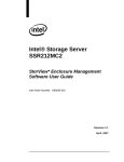
Drive carrier module faults
Use the green LED and orange LED mounted on the front of each drive carrier module to monitor
disk drive status. The LEDs indicate the following:
State
Green
Orange
No drive installed
Off
Off
Drive power ON
On
Off
Drive activity
On/Blink off
Off
Drive impacted
On
Blink
Drive fault
On
On
Power control circuit failure
Off
On
Important
The LED may be off for a length of time during power up.
Green (activity) LED
Orange (fault) LED
Auto start failure
Unless otherwise selected at installation, all drives in the enclosure should automatically start after
you turn on the enclosure. If this does not occur, there is a power problem (an alarm and power
fault indication would normally be active).
16
www.gateway.com
Troubleshooting
The following sections describe problems, with possible solutions, which can occur with your
Gateway E-842R Storage Area Network.
System faults
Symptom
Cause
Action
1. The CONTROLLER FAULT
LED lights orange on the
module.
2. The audible alarm sounds.
The ESI processor has
detected an internal
fault on one of the
following modules:
■
Power supply
■
Cooling
■
RAID
Replace the faulty module as appropriate.
Also see “Thermal warnings” on page 18.
Power supply faults
Symptoms
■
■
■
Causes
Ops panel SYSTEM FAULT LED
is orange.
An orange LED on one or
more power supply modules.
Audible alarm sounding.
■
■
■
■
Any power fault.
A fan failure.
A thermal condition which could
cause power supply module
overheating.
Fault on one of the following
modules:
■
Power supply
■
Cooling
■
RAID
■
Removal of 1 power supply
module.
Actions
■
■
■
■
Make sure that the AC power connections to power
supply module are live.
Disconnect the power supply module from AC power
and remove the module from the system, then
re-install. If the problem persists, replace the power
supply module.
Reduce the ambient temperature.
Replace the faulty module, as appropriate:
■
Power supply
■
Cooling
■
RAID
Thermal control
The Gateway E-842R storage enclosure uses extensive thermal monitoring and takes a number of
actions to make sure that component temperatures are kept low and that acoustic noise is
minimized. Airflow is from front to rear of the enclosure.
Symptom
Cause
Action
If the ambient air is cool
(below 77°F (25°C)) and the
fans are observed to increase
in speed, some airflow
restriction may be causing
the internal temperature rise.
Note: This is not a fault
condition.
The first stage in the thermal control process
is for the fans to automatically increase in
speed when a thermal threshold is reached.
This may be caused by higher ambient
temperatures in the local environment and
may be perfectly normal.
Note: This threshold changes according to the
number of drives and power supplies
installed.
■
■
■
■
■
Check the installation for any airflow
restrictions at either the front or rear of the
enclosure. A minimum gap of 1 inch (25 mm)
at the front and 2 inches (50 mm) at the rear
is recommended.
Check for restrictions caused by dust build-up
and clean as appropriate.
Check for excessive re-circulation of heated air
from the rear to the front. Installing in a fully
enclosed rack installation is not
recommended.
Make sure that all blank modules are installed.
Reduce the ambient temperature.
17
CHAPTER 4: Troubleshooting
Thermal alarm
Symptom
■
■
■
■
Cause
Ops panel SYSTEM FAULT LED
is orange.
An orange LED on one or
more power supply module.
An audible alarm is sounding.
Air temperature in the exiting
power supply module is
above 131°F (55°C).
If the internal temperature
measured in the airflow
through the enclosure
exceeds a pre-set threshold, a
thermal alarm sounds.
Cooling module failure.
■
■
Action
■
■
■
■
■
■
Make sure that the local ambient environment
temperature is below the upper 104°F (40°C)
specification.
Check the installation for any airflow restrictions at
either the front or rear of the enclosure. A minimum gap
of .98 inch (25 mm) at the front and 1.97 inches (50 mm)
at the rear is recommended.
Check for restrictions caused by dust build-up and clean
as appropriate.
Check for excessive re-circulation of heated air from the
rear to the front. Installing in a fully enclosed rack
installation is not recommended.
If possible, shutdown the enclosure and investigate the
problem before continuing.
Replace the cooling module.
Thermal warnings
Symptom
■
■
All orange LEDs on the Ops
panel and on all drive bays are
flashing.
The audible alarm sounds
almost continuously and
cannot be muted.
Cause
Action
The temperature is higher than the
thermal alarm threshold (this should
already have been activated).
OR - All fans have failed.
OR - Only 1 fan is operating and the
internal temperature is 104°F (40°C) or
above.
■
■
■
■
Power off immediately.
Check for airflow restrictions.
Check for power supply module faults.
Check for excessive local temperatures.
Hardware faults
Make sure that you have obtained a replacement module of the same type before removing any
faulty module.
Caution
If your Gateway E-842R enclosure is turned on and you remove any module, replace
it immediately. If the enclosure is used with plug-in modules, dummy carriers, or blank
modules missing for more than a few minutes, the enclosure can overheat, causing power
failure and data loss. Such use invalidates the warranty.
• Replace a faulty drive with a drive of the same type and equal or greater capacity.
• All drive bays must have a drive carrier or dummy carrier module installed in order to
•
18
maintain a balanced airflow.
All of the supplied plug-in power supply units, electronics modules, dummy carriers, and
blank modules must be installed for the air to flow correctly around the cabinet.
www.gateway.com
Continuous operation during replacement
Important
The power supply module replacement time must be as short as possible because
the Gateway E-842R enclosure is designed to operate with two power supply modules
installed.
Important
The fans within the cooling module are not user replaceable. In the event of a cooling
fan failure, the complete cooling module must be replaced.
Depending on how your Gateway E-842R enclosure is set up, you can normally replace a failed
disk unit without interrupting the use of the system.
In addition, each enclosure contains two power supply modules, either of which can maintain
power and cooling to the subsystem while the other is replaced.
Ops panel
Important
The Ops panel is an integral part of the enclosure assembly and can only be replaced
with a replacement enclosure. The enclosure should only be replaced by trained personnel.
Replacing a module
Caution
When replacing a module, never leave an empty space in the rear of the enclosure.
Obtain a replacement before removing the problem module.
Caution
Observe all conventional ESD precautions when handling modules and components.
Avoid contact with such things as backplane components and module connectors.
See “Getting Started” on page 15 for information on the initial installation of the plug-in modules
in your Gateway E-842R enclosure.
Power supply modules
Caution
The Gateway E-842R enclosure must only be operated with two power supply
modules installed.
AC Power supply module
Caution
Do not remove the faulty power supply module unless you have a replacement unit
of the correct type ready for insertion. The system must not be operated without both power
supply modules in place.
Removing a power supply module
You can continue working while replacing the faulty module because there should always be two
power supply modules in place.
19
CHAPTER 4: Troubleshooting
Warning
Do not remove covers from the power supply modules. There is a danger of electric
shock inside.
To remove a power supply module:
1 Make sure that you identify the faulty power supply module correctly. The Module Fault LED
on the faulty power supply module lights orange.
2 Disconnect the power supply cord.
3 Push the latch on the power supply module handle to the right, then grip the handle and
pull the power supply module out of the enclosure.
Installing a power supply module
Caution
Do not mix power supply modules of different types or makes.
To install a power supply module:
1 Check for damage, especially to the rear connector on the power supply module.
Caution
Handle the module carefully and avoid damaging the connector pins. Do not
install the module if any pins appear to be bent.
2 Slide the module into the enclosure (see “To install a power supply module:” on page 20).
3 Push the module until you hear a click as the handle latch engages.
20
www.gateway.com
4 Connect the power supply cord to the power source.
Important
The alarm sounds until the new power supply module is operating correctly.
Cooling module
Removing the cooling module
To remove the cooling module:
1 Grasp the latch between your thumb and forefinger. Squeeze your thumb and forefinger
together to release the latch.
2 Pull the latch outward to pull the module out of the enclosure.
3 Remove the module.
21
CHAPTER 4: Troubleshooting
Installing the cooling module
Caution
Handle the module carefully and avoid damaging the connector pins. Do not install
the module if any pins appear to be bent.
To install the cooling module:
1 Check for damage, especially to the rear connector on the supply.
2 With the latch in the open position, slide the module into the enclosure until the latch engages
automatically.
3 Secure the module by manually closing the latch. You should hear a click when the module
latch engages.
Controller module
Caution
If only one controller module is installed, a blank module must be installed in the
unused slot. If the slot is left open, the drive may overheat.
The following procedures apply to both the controller module and the blank module.
Removing a controller module
Caution
Do not remove this module unless a replacement can be installed immediately. The
system must not be run without all modules in place.
To remove a controller module:
1 Using two hands, grasp each latch between the thumb and forefinger of each hand. Squeeze
your thumb and forefinger together to release the latches.
2 Pull the latches outward to pull the module out of the enclosure.
22
www.gateway.com
3 Grip the latch handles and remove the module.
Installing a RAID controller module
To install a RAID controller module:
1 Check for damage, especially to the interface connector. Do not install if the pins are bent.
2 With the latches in the open position, slide the RAID controller module into the enclosure
until the latches engage automatically.
23
CHAPTER 4: Troubleshooting
3 Secure the module by manually closing the latches. You should hear a click when the latches
engage.
The controller module takes up to one minute to re-initialize onto the loop after re-cabling.
Battery module
Warning
There is a danger of explosion if the battery is incorrectly replaced.
Dispose of used batteries in accordance with the manufacturer’s instructions and national
regulations.
24
www.gateway.com
Removing a battery module
To remove a battery module:
• Operate the release latch and slide the battery module out of the controller module.
Installing a battery module
To install a battery module:
1 Check for damage. Do not install if there are any outer signs of damage.
2 Slide the battery module into the vacant slot on the right side of the controller module until
it clicks into place.
Removing and replacing a disk I/O module
To remove and replace a disk I/O module in an expansion enclosure, follow the procedures for
removing and replacing a controller module (see “Controller module” on page 22).
25
CHAPTER 4: Troubleshooting
Drive carrier module
Caution
Observe all conventional ESD precautions when handling modules and components.
Avoid contact with such things as backplane components and module connectors.
Removing a drive carrier module
To remove a drive carrier module:
1 Release the carrier handle by pressing the latch in the handle towards the right. The
anti-tamper lock must be off.
Caution
Damage can occur to a drive if it is removed while still spinning. We
recommend that you perform all steps in the following procedure to ensure that the
drive has stopped prior to removal.
2 Gently withdraw the drive carrier module approximately 1 inch (25 mm) and wait 30 seconds
to let the drive spin down.
3 Withdraw the module from the drive bay.
26
www.gateway.com
Installing a drive carrier module
Caution
All drive bays must have drive carrier modules or dummy carrier modules installed
to maintain a balanced airflow.
Dummy carrier modules are provided for fitting in all unused drive bays. They are designed
as integral drive module front caps and must be installed in all unused drive bays to maintain
a balanced airflow. If you plan to remove a drive for more than a few minutes, we recommend
that you temporarily install a dummy carrier module in its place.
Drive carrier configuration
Before you install the drive carrier modules in your E-842R enclosure, see “Planning your
installation” on page 16 for system configuration information.
Installation procedure
Important
Make sure that the carrier is orientated so that the drive is uppermost and the handle
opens from the left.
To install a drive carrier module:
1 Release the carrier handle by pressing the latch in the handle towards the right, then insert
the carrier into the enclosure.
If the anti-tamper locks have been activated, see “Activating the anti-tamper locks” on
page 27.
2 Gently slide the carrier all the way into the enclosure until it is stopped by the lever on the
right of the carrier.
Caution
Make sure that the carriers are fully engaged in the enclosure.
27
CHAPTER 4: Troubleshooting
3 Secure the carrier into the slot (the latch on the base of the carrier engages a slot in the
enclosure). Continue to push firmly until the handle fully engages. You should hear a click
when the latch engages and holds the handle closed.
Dummy drive carrier module removal and replacement
Dummy drive carrier modules are removed and replaced in the enclosure by pulling the dummy
module out of the enclosure or pushing it into place.
Telephone support
Gateway offers a wide range of customer service, technical support, and information services.
Telephone numbers
You can access the following services through your telephone to get answers to your questions:
28
Resource
Service description NEW
How to reach
Gateway
Customer Care
Talk to a Gateway Customer Care representative about a
non-tutorial technical support question.
877-485-1464 (US)(option #6)
800-846-3609 (Canada and Puerto
Rico)
605-232-2191
(all other countries)
Sales,
accounting, and
warranty
Get information about available systems, pricing, orders,
billing statements, warranty service, or other non-technical
issues.
800-846-2000 (US)
888-888-2037 (Canada)
APPENDIXA
Specifications
•
•
•
•
•
•
•
•
•
Dimensions
Weight
AC power (350 W power supply module)
Power supply module safety and EMC compliance
Environment
Interfaces
Controller module specification
Disk I/O module specification
Drive carrier module specification
29
APPENDIX A: Specifications
Dimensions
Enclosure
inches
mm
Height
3.46
87.9
Width across the mounting flange
19
483
Width across the body of the enclosure
17.6
447
Depth from the flange to the rear of the enclosure body
21.65
550
Depth from the flange to the maximum extremity of enclosure
(rear hold down)
22.72
577
Depth from the flange to the furthest extremity at the front of the
enclosure
1.44
36.5
We recommend that a rack with a depth of no less than 27.55 inches (700 mm) be used with this
product.
Weight
Maximum configuration
70.4 lb. (32 kg)
Empty enclosure
19.8 lb. (9 kg)
AC power (350 W power supply module)
30
Voltage range
100~240 VAC Rated
Frequency
50/60 Hz
Inrush current
<30 A @ 230 VAC
Power factor
>0.98
Harmonics
Meets EN61000-3-2
www.gateway.com
Power consumption
Power consumption of enclosure with 12x SAS drives running I/O, powered by a single power
supply module (Power One power supply module) with extended power lead between the power
supply module and the I/O backplane and with two controllers installed at IDLE and ACTIVE
operation.
Caution
The enclosure must be operated with two power supplies in place.
Voltage Rail
IDLE
ACTIVE
Average
Peak
Average
Peak
5V
11.51A
13.2A
13.53A
15.7A
12V
12.29A
15.1A
13.17A
20.1A
Power supply module safety and EMC compliance
Safety compliance
UL 60950-1
IEC 60950-1
EN 60950-1
EMC compliance
CFR47 Part 15B Class A
EN55022
EN55024
Environment
Temperature Range
Relative Humidity
Max. Wet Bulb
Operational
41°F to 104°F (5°C to
40°C)
8% to 80%
non-condensing
73.4°F (23°C)
Non-Operational
33.8°F to 122°F (1°C to
50°C)
8% to 80%
non-condensing
80.6°F (27°C)
Storage
33.8°F to 140°F (1°C to
60°C)
8% to 80%
non-condensing
84.2°F (29°C)
Shipping
-40°F to 140°F (-40°C to
60°C)
5% to 100%
non-precipitating
84.2°F (29°C)
Airflow
The system must be operated with a low pressure rear exhaust
installation (the back pressure created by the rack doors and obstacles
not to exceed 5 pascals [0.5mm Water gauge])
Altitude, Operational
0 to 10,000 ft. (0 to 3045 m)
Altitude, Non-Operational
-1000 to 40,000 ft. (-305 to 12,192 m)
31
APPENDIX A: Specifications
Shock, Operational
Vertical axis 5 g peak 1/2 sine, 10 ms
Shock, Non-Operational
30 g 10 ms 1/2 sine
Vibration, Operational
0.21 grms 5-500 Hz Random
Vibration, Non-Operational
1.04 grms 2-200 Hz Random
Vibration, Relocation
0.3 g 2-200 Hz sine
Acoustics
Sound Power Operating:
Less than 58 dB LwA measured at 73.4°F (23°C).
Sound Pressure Operating:
Less than 6.8 Bels LwA measured at 73.4°F (23°C).
Orientation & Mounting
19" rack mount (2 EIA units)
■
Rack Rails
To fit 31.5 inches (800 mm) depth racks, compliant with IEC 297
■
Rack Characteristics
Back pressure not exceeding 5 pascals (0.5mm water gauge)
Safety & Approvals
■
CE, UL, cUL
EMC
EN55022 (CISPR - A), FCC A
Interfaces
Drive support
See drive carrier specification
Attachment
■
1 domain of 12 drives per controller module
■
(2) SAS Host Ports (IN) - 2 x SFF8470 connector (4 lane)
(1) SAS expansion port (OUT) - 1 x SFF8470 connector (4 lane)
■
Controller module specification
Dimensions (internal)
4 inches x 10.5 inches (103 mm x 267 mm)
Component board - 4 inches x 9.5 inches (103 mm x 240 mm)
Speed
■
Mounting
Back, horizontal in Bay 4 (see “Enclosure chassis” on page 3)
Connectors
■
■
■
■
■
Power consumption
32
Host ports: two 3 Gb/sec SAS
Drive ports: 3 GB SAS, creates connections to a single domain of 12 drives
(2) 4 Lane SAS SFF connectors for IN 0 (Port 0) and IN 1 (Port 1) ports
(1) 4 Lane SAS Expansion SFF connector OUT ports
(1) RJ45, 10/100BaseT Ethernet port
(1) RS232 port
40 W
www.gateway.com
LED functions
LED functions
LED state
Definition
Battery fault
Orange
When lit, this LED indicates that the backup battery unit
is missing, has low voltage, has experienced a time-out
on charge, indicated a faulty battery, or has experienced
a fault in the charging circuitry.
Cache active
Orange
When lit, this LED indicates that the RAID controller cache
has data saved in memory but not written to the disk
array.
Controller activity on drive bank 0
Orange
When lit, this LED indicates activity on the Bank 0 disk
drives.
Controller activity on drive bank 1
Orange
When lit, this LED indicates activity on the Bank 1 disk
drives.
Controller OK
Green
When lit, this LED indicates that RAID controller activity
is normal.
Controller fault
Orange
When lit, this LED indicates that a RAID controller fault
has occurred.
Ethernet status
Green
When lit, this LED indicates that the Ethernet port has a
valid connection.
Orange
When lit, this LED indicates that the Ethernet port has
activity.
Green
When lit, these LEDs show I/O activity on the specific port
lane indicated.
SAS activity*
* These LEDs blink on and off when there is module activity.
Disk I/O module specification
Dimensions (internal)
4 inches x 10.5 inches (103 mm x 267 mm)
Component board - 4 inches x 9.5 inches (103 mm x 240 mm)
Speed
■
Connectors
■
■
■
Host ports: two 3 Gb/sec SAS
Drive ports: 3 GB SAS, creates connections to a single domain of 12 drives
(1) Host Port (IN) - SFF8470 connector (4 lane)
(1) expansion port (OUT) - SFF8470 connector (4 lane)
■
Attachment
■
■
(1) SAS 4 lane 3 Gbit/sec wide port Host connector
(1) SAS 4 lane 3 Gbit/sec wide port Expansion connector
LED functions
LED
LED state
Definition
IN (1-4)
Green
When lit, this LED indicates I/O activity on the specified
SAS port lane.
OUT (1-4)
Green
When lit, this LED indicates I/O activity on the specified
SAS port lane.
* These LEDs blink on and off when there is module activity.
33
APPENDIX A: Specifications
Drive carrier module specification
Important
Operating E-842R enclosures with non-approved drives may invalidate the warranty.
Contact Gateway Customer Care for details of approved drives.
The drive carrier module is not available separately.
34
Module dimensions
Height 1.06” (27.05 mm(
Width 4.19” (106.55 mm)
Depth 8.25” (209.55 mm)
Weight
1.91 lbs (0.86 kg) (with 1.0” 750 GB drive)
Operating temperature
41°F to 104°F (5°C to 40°C) (when installed in an E-842R storage
enclosure with dual power supply modules)
Power dissipation
18.5 Watts maximum
APPENDIXB
Legal Information
35
APPENDIX B: Legal Information
Regulatory compliance statements
United States of America
Federal Communications Commission (FCC)
Unintentional emitter per FCC Part 15
FCC Part 15 Class A Statement
The server is designated as complying with Class A requirements if it bares the following text on the rating label:
This device complies with Part 15 of the FCC Rules. Operation is subject to the following two conditions:
(1) This device may not cause harmful interference.
(2) This device must accept any interference received, including interference that may cause undesired operation.
This device has been tested and found to comply with the limits for a Class A digital device, pursuant to Part 15 of the FCC rules. These
limits are designed to provide reasonable protection against harmful interference in a commercial installation. This equipment
generates, uses, and can radiate radio frequency energy and, if not installed and used in accordance with the instructions, may cause
harmful interference with radio communications. Operation of this equipment in a residential area is likely to cause harmful
interference, in which case you will be required to correct the interference at your own expense.
Caution
Changes or modifications not expressly approved by Gateway could void the FCC
compliance and negate your authority to operate the product.
Telecommunications per FCC part 68
(applicable to products fitted with USA modems)
Your modem complies with Part 68 of the Federal Communications Commission (FCC) rules. On the computer or modem card is a label
that contains the FCC registration number and Ringer Equivalence Number (REN) for this device. If requested, this information must be
provided to the telephone company.
An FCC-compliant telephone line cord with a modular plug is required for use with this device. The modem is designed to be connected
to the telephone network or premises wiring using a compatible modular jack which is Part 68-compliant. See installation instructions
for details.
The Ringer Equivalence Number (REN) is used to determine the number of devices which may be connected to the telephone line.
Excessive RENs on a telephone line may result in the devices not ringing in response to an incoming call. In most areas, the sum of
RENs should not exceed five (5.0). To be certain of the number of devices that may be connected to a line, as determined by the total
RENs, contact the local telephone company.
If this device causes harm to the telephone network, the telephone company will notify you in advance that temporary discontinuance
of service may be required. The telephone company may request that you disconnect the equipment until the problem is resolved.
The telephone company may make changes in its facilities, equipment, operations, or procedures that could affect the operation of
this equipment. If this happens, the telephone company will provide advance notice in order for you to make necessary modifications
to maintain uninterrupted service.
This equipment cannot be used on telephone company-provided coin service. Connection to party line service is subject to state
tariffs. Contact the state public utility commission or public service commission for information.
When programming or making test calls to emergency numbers:
■
Remain on the line and briefly explain to the dispatcher the reason for the call.
Perform such activities in the off-peak hours such as early morning or late evenings.
The United States Telephone Consumer Protection Act of 1991 makes it unlawful for any person to use a computer or other electronic
device to send any message via a telephone fax machine unless such message clearly contains, in a margin at the top or bottom of
each transmitted page or on the first page of the transmission, the date and time it is sent, an identification of the business, other
entity, or other individual sending the message, and the telephone number of the sending machine or such business, other entity, or
individual. Refer to your fax communication software documentation for details on how to comply with the fax-branding requirement.
■
FCC declaration of conformity
Responsible party:
Gateway Companies, Inc.
610 Gateway Drive, North Sioux City, SD 57049
(605) 232-2000 Fax: (605) 232-2023
Product:
■
36
Gateway E-842R SAS RAID Storage Solution
www.gateway.com
For unique identification of the product configuration, please submit the 10-digit serial number found on the product to the
responsible party.
Caution
Changes or modifications not expressly approved by Gateway could void the FCC
compliance and negate your authority to operate the product.
This device complies with Part 15 of the FCC Rules. Operation of this product is subject to the following two conditions: (1) this device
may not cause harmful interference, and (2) this device must accept any interference received, including interference that may cause
undesired operation.
Canada
Industry Canada (IC)
Unintentional emitter per ICES-003
This digital apparatus does not exceed the Class A limits for radio noise emissions from digital apparatus as set out in the radio
interference regulations of Industry Canada.
Le présent appareil numérique n’émet pas de bruits radioélectriques dépassant les limites applicables aux appareils numériques de
Classe A prescrites dans le règlement sur le brouillage radioélectrique édicté par Industrie Canada.
Telecommunications per Industry Canada CS03
(for products fitted with an IC-compliant modem)
The Industry Canada label identifies certified equipment. This certification means that the equipment meets certain
telecommunications network protective, operation, and safety requirements. The Department does not guarantee the equipment will
operate to the users’ satisfaction.
Before installing this equipment, users should make sure that it is permissible to be connected to the facilities of the local
telecommunications company. The equipment must also be installed using an acceptable method of connection. In some cases, the
inside wiring associated with a single-line individual service may be extended by means of a certified connector assembly. The
customer should be aware that compliance with the above conditions may not prevent degradation of service in some situations.
Repairs to certified equipment should be made by an authorized Canadian maintenance facility designated by the supplier. Any
repairs or alterations made by the user to this equipment, or equipment malfunctions, may give the telecommunications company
cause to request the user to disconnect the equipment.
Warning
To avoid electrical shock or equipment malfunction do not attempt to make electrical
ground connections by yourself. Contact the appropriate inspection authority or an
electrician, as appropriate.
Users should make sure, for their own protection, that the electrical ground connections of the power utility, telephone lines, and
internal metallic water pipe system, if present, are connected together. This precaution may be particularly important in rural areas.
The Ringer Equivalence Number (REN) assigned to each terminal device provides an indication of the maximum number of terminals
allowed to be connected to a telephone interface. The termination on an interface may consist of any combination of devices subject
only to the requirement that the sum of the Ringer Equivalence Numbers of all the devices does not exceed 5.
Laser safety statement
All Gateway systems equipped with CD and DVD drives comply with the appropriate safety standards, including IEC 825. The laser
devices in these components are classified as “Class 1 Laser Products” under a US Department of Health and Human Services (DHHS)
Radiation Performance Standard. Should the unit ever need servicing, contact an authorized service location.
Warning
Use of controls or adjustments or performance of procedures other than those
specified in this manual may result in hazardous radiation exposure. To prevent exposure
to laser beams, do not try to open the enclosure of a CD or DVD drive.
California Proposition 65 Warning
Warning
This product contains chemicals, including lead, known to the State of California to
cause cancer and/or birth defects or reproductive harm.
37
APPENDIX B: Legal Information
Environmental information
The product you have purchased contains extracted natural resources that have been used in the manufacturing process. This product
may contain substances known to be hazardous to the environment or to human health.
To prevent releases of harmful substances into the environment and to maximize the use of our natural resources, Gateway provides
the following information on how you can responsibly recycle or reuse most of the materials in your “end of life” product.
Waste Electrical and Electronic Equipment (commonly known as WEEE) should never be disposed of in the municipal waste stream
(residential garbage collection). The “Crossed-Out Waste Bin” label affixed to this product is your reminder to dispose of your “end of
life” product properly.
Substances such as glass, plastics, and certain chemical compounds are highly recoverable, recyclable, and
reusable. You can do your part for the environment by following these simple steps:
■
When your electrical or electronic equipment is no longer useful to you, “take it back” to your local or regional
waste collection administration for recycling.
■
In some cases, your “end of life” product may be “traded in” for credit towards the purchase of new Gateway
equipment. Call Gateway to see if this program is available in your area.
■
If you need further assistance in recycling, reusing, or trading in your “end of life” product, you may contact us at
the Customer Care number listed in your product’s user guide and we will be glad to help you with your effort.
Finally, we suggest that you practice other environmentally friendly actions by understanding and using the energy-saving features of
this product (where applicable), recycling the inner and outer packaging (including shipping containers) this product was delivered in,
and by disposing of or recycling used batteries properly.
With your help, we can reduce the amount of natural resources needed to produce electrical and electronic equipment, minimize the
use of landfills for the disposal of “end of life” products, and generally improve our quality of life by ensuring that potentially
hazardous substances are not released into the environment and are disposed of properly.
Notices
Copyright © 2007 Gateway, Inc.
All Rights Reserved
7565 Irvine Center Drive
Irvine, CA 92618-2930 USA
All Rights Reserved
This publication is protected by copyright and all rights are reserved. No part of it may be reproduced or transmitted by any means or
in any form, without prior consent in writing from Gateway.
The information in this manual has been carefully checked and is believed to be accurate. However, changes are made periodically.
These changes are incorporated in newer publication editions. Gateway may improve and/or change products described in this
publication at any time. Due to continuing system improvements, Gateway is not responsible for inaccurate information which may
appear in this manual. For the latest product updates, consult the Gateway Web site at www.gateway.com. In no event will Gateway
be liable for direct, indirect, special, exemplary, incidental, or consequential damages resulting from any defect or omission in this
manual, even if advised of the possibility of such damages.
In the interest of continued product development, Gateway reserves the right to make improvements in this manual and the products
it describes at any time, without notices or obligation.
Trademark Acknowledgments
Trademarks used herein are trademarks or registered trademarks of Gateway, Inc. in the United States and other countries. All other
brands and product names are trademarks or registered trademarks of their respective companies.
38
APPENDIXC
Safety Information
39
APPENDIX C: Safety Information
Important safety information
Warning
Always follow these instructions to help guard against personal injury and damage
to your Gateway system.
Your Gateway system is designed and tested to meet the latest standards for safety of information technology equipment. However, to
ensure safe use of this product, it is important that the safety instructions marked on the product and in the documentation are
followed.
Setting up your system
■
■
■
■
■
■
■
■
■
Read and follow all instructions marked on the product and in the documentation before you operate your system. Retain all safety
and operating instructions for future use.
Do not use this product near water or a heat source such as a radiator.
Set up the system on a stable work surface.
The product should be operated only from the type of power source indicated on the rating label.
If your computer has a voltage selector switch, make sure that the switch is in the proper position for your area. The voltage
selector switch is set at the factory to the correct voltage.
Openings in the computer case are provided for ventilation. Do not block or cover these openings. Make sure you provide adequate
space, at least 6 inches (15 cm), around the system for ventilation when you set up your work area. Never insert objects of any kind
into the computer ventilation openings.
Some products are equipped with a three-wire power cord to make sure that the product is properly grounded when in use. The
plug on this cord will fit only into a grounding-type outlet. This is a safety feature. If you are unable to insert the plug into an outlet,
contact an electrician to install the appropriate outlet.
If you use an extension cord with this system, make sure that the total ampere rating on the products plugged into the extension
cord does not exceed the extension cord ampere rating.
If your system is fitted with a TV Tuner, cable, or satellite receiver card, make sure that the antenna or cable system is electrically
grounded to provide some protection against voltage surges and buildup of static charges.
Care during use
■
■
■
■
Do not walk on the power cord or allow anything to rest on it.
Do not spill anything on the system.
Some products have a replaceable CMOS battery on the system board. There is a danger of explosion if the CMOS battery is
replaced incorrectly. Replace the battery with the same or equivalent type recommended by the manufacturer. Dispose of batteries
according to the manufacturer’s instructions.
When the computer is turned off, a small amount of electrical current still flows through the computer. To avoid electrical shock,
always unplug all power cables and modem cables from the wall outlets before cleaning the system.
Warning
This unit has two power supplies. To remove power from all internal circuitry you must
disconnect both power cords.
■
Unplug the system from the wall outlet and refer servicing to qualified personnel if:
■
The power cord or plug is damaged.
■
Liquid has been spilled into the system.
■ The system does not operate properly when the operating instructions are followed.
■
The system was dropped or the cabinet is damaged.
■
The system performance changes.
Replacement parts and accessories
Use only replacement parts and accessories recommended by Gateway.
Warning
To reduce the risk of fire, use only No. 26 AWG or larger telecommunications line cord.
Important
Do not use Gateway products in areas classified as hazardous locations. Such areas
include patient care areas of medical and dental facilities, oxygen-laden environments, or
industrial facilities.
40
Index
A
H
T
accessories
HBA 18
safety precautions 68
help
alarm mute button 44
telephone support 56
anti-static wrist or ankle strap 18 Host Bus Adaptors (HBAs) 23
anti-tamper lock 12, 27, 54
I
Audible Alarm 43, 44, 45, 46
IEC 320 connector 28
audible alarm 5, 43, 45, 46
auto start failure 44
telephone support 56
troubleshooting
telephone support 56
U
Unpacking the Enclosure System
18
UPS 18
L
B
backplane 2, 3, 18, 47, 54
bay 16
C
CD
External Storage 18, 19
chassis 3
controller module 52
D
disc 37
disk drive 3, 17
disk drive LEDs 37
drive bay 16
drive carrier 56
drive carrier handles 12
drive carrier module 3, 12, 17, 37,
44, 54, 55
Drive Location Rules 26
dummy carrier module 13, 55
E
enclosure 2, 8, 13, 46
enclosure bay numbering
convention 17
enclosure system
interface/operators
panel 4
ESD 18, 47
ESD precautions 54
ESI processor 45
Ethernet Connection 24
External Storage CD 18, 19
F
fan failure 45
G
grounding system checks 28
LED 4, 6, 40, 41, 43, 44, 45, 46
O
operator’s (Ops) panel 2, 4, 28, 42,
47
Ops panel LEDs 36, 42
P
plug-in module 2, 3, 16
Power Distribution Unit 18
power on 36
power supply cord 28, 48
power supply module 46
power supply module LEDs 36, 41
power supply module voltage
operating ranges 5
power supply/cooling 3, 6, 16, 28,
40, 46, 47, 49
R
rack mounting 3
rack mounting rail kit 19, 20
RAID controller module 45, 51
replacing a module 47
RJ45 10/100/BaseT Ethernet port
9, 24
RS232 socket 9
S
safety
general precautions 68
SAS patch cables 25
SES 18
setting up
safety precautions 68
SFP port 8
Small Form Factor Pluggable (SFP)
modules 8
starting drives 37
StorView ® Storage Management
software 9
69
Index
70
A MAN E-842R SAS USR GDE R0 05/07