1
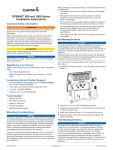
3 Select Download next to "Garmin Marine Network with SD GPSMAP 7400/7600 Series ® Installation Instructions Important Safety Information WARNING See the Important Safety and Product Information guide in the product box for product warnings and other important information. When connecting the power cable, do not remove the in-line fuse holder. To prevent the possibility of injury or product damage caused by fire or overheating, the appropriate fuse must be in place as indicated in the product specifications. In addition, connecting the power cable without the appropriate fuse in place will void the product warranty. CAUTION Always wear safety goggles, ear protection, and a dust mask when drilling, cutting, or sanding. NOTICE When drilling or cutting, always check what is on the opposite side of the surface. To obtain the best performance and to avoid damage to your boat, install the device according to these instructions. Read all installation instructions before proceeding with the installation. If you experience difficulty during the installation, contact Garmin Product Support. ® Registering Your Device Help us better support you by completing our online registration today. • Go to http://my.garmin.com. • Keep the original sales receipt, or a photocopy, in a safe place. Contacting Garmin Product Support • Go to www.garmin.com/support for in-country support information. • In the USA, call 913-397-8200 or 1-800-800-1020. • In the UK, call 0808 238 0000. • In Europe, call +44 (0) 870 850 1241. Software Update You may need to update the device software when you install the device or add an accessory to the device. Loading the New Software on a Memory Card 1 Insert a memory card into the card slot on the computer. 2 Go to www.garmin.com/support/software/marine.html. December 2014 4 5 6 7 card." Read and agree to the terms. Select Download. Select Run. Select the drive associated with the memory card, and select Next > Finish. Updating the Device Software Before you can update the software, you must obtain a software-update memory card or load the latest software onto a memory card. 1 Turn on the chartplotter. 2 After the home screen appears, insert the memory card into the card slot. NOTE: In order for the software update instructions to appear, the device must be fully booted before the card is inserted. 3 Follow the on-screen instructions. 4 Wait several minutes while the software update process completes. The device returns to normal operation after the software update process is complete. 5 Remove the memory card. NOTE: If the memory card is removed before the device restarts fully, the software update is not complete. Tools Needed • Drill and drill bits ◦ Bail mount: drill bits appropriate for the surface and hardware ◦ Flush mount: 13 mm (1/2 in.) drill bit, 7.2 mm (5/16 in.), and 3.5 mm (1/8 in.) drill bit • #2 Phillips screwdriver • Jigsaw or rotary tool • File and sandpaper • Marine sealant (recommended) Mounting Considerations NOTICE This device should be mounted in a location that is not exposed to extreme temperatures or conditions. The temperature range for this device is listed in the product specifications. Extended exposure to temperatures exceeding the specified temperature range, in storage or operating conditions, may cause device failure. Extreme-temperature-induced damage and related consequences are not covered by the warranty. Using the included hardware and template, you can mount the device using one of two methods. You can use the included bracket and hardware to bail mount the device, or you can use the included template and hardware to flush mount the device in the dashboard. When selecting a mounting location, you should observe these considerations. • The location should provide optimal viewing as you operate your boat. • The location should allow for easy access to all device interfaces, such as the keypad, touchscreen, and card reader, if applicable. • The location must be strong enough to support the weight of the device and protect it from excessive vibration or shock. • To avoid interference with a magnetic compass, the device should not be installed closer to a compass than the Printed in Taiwan 190-01841-02_0A compass-safe distance value listed in the product specifications. • The location must allow room for the routing and connection of all cables. Bail Mounting the Device NOTICE If you are mounting the bracket on fiberglass with screws, it is recommended to use a countersink bit to drill a clearance counterbore through only the top gel-coat layer. This will help to avoid any cracking in the gel-coat layer when the screws are tightened. The bail-mounting hardware (screws and washers, or nuts, washers, and bolts) is not included. Before you can bail mount the device, you must choose mounting hardware that fits the holes in the bail mount bracket and securely attaches it to your specific mounting surface. The size of the pilot holes required depends on the mounting hardware you choose. 1 Using the included bail mount bracket À as a template, mark the location of the four pilot holes Á. 7 After the device fits correctly in the cutout, ensure the mounting holes on the device line up with the larger 7.2 mm (5/16 in.) holes on the template. 8 If the mounting holes on the device do not line up, mark the new hole locations. 9 Using a 7.2 mm (5/16 in.) drill bit, drill the larger holes. 10 Starting in one corner of the template, place a nut plate À over the larger hole Á drilled in step 9. The smaller 3.5 mm (1/8 in.) hole  on the nut plate should line up with the smaller hole on the template. 11 If the smaller 3.5 mm (1/8 in.) hole on the nut plate does not line up with the smaller hole on the template, mark the new hole location. 12 Repeat steps 10 and 11 to verify placement of the remaining nut plates and holes on the template. 13 Using a 3.5 mm (1/8 in.) drill bit, drill the smaller holes. 14 Remove the template from the mounting surface. 15 Starting in one corner of the mounting location, place a nut plate à on the back of the mounting surface, lining up the large and small holes. The raised portion of the nut plate should fit into the larger hole. 2 Using a drill bit appropriate for your mounting hardware, drill the pilot holes. 3 Secure the bail mount bracket to the surface using your mounting hardware Â. 4 Install the bail mount knobs à on the sides of the device. 5 Place the device in the bail mount bracket, and tighten the bail mount knobs. Flush Mounting the Device NOTICE Be careful when cutting the hole to flush mount the device. There is only a small amount of clearance between the case and the mounting holes, and cutting the hole too large could compromise the stability of the device after it is mounted. The included template and hardware can be used to flush mount the device in your dashboard. 1 Trim the template, and make sure it fits in the location where you want to mount the device. 2 Secure the template to the selected location. 3 Using a 13 mm (1/2 in.) drill bit, drill one or more of the holes inside the corners of the solid line on the template to prepare the mounting surface for cutting. 4 Using a jigsaw or a rotary tool, cut the mounting surface along the inside line on the template. 5 Place the device in the cutout to test the fit. 6 If necessary, use a file and sandpaper to refine the size of the cutout. 2 16 Secure the nut plate to the mounting surface by fastening an included M3 screw Ä through the smaller 3.5 mm (1/8 in.) hole. 17 Repeat steps 15–16 to secure the remaining nut plates to the mounting surface. 18 Install the rubber gasket Å on the back of the device. The pieces of the rubber gasket have adhesive on the back. Make sure you remove the protective liner before installing them on the device. 19 If you will not have access to the back of the device after you mount it, connect all necessary cables to the device before placing it into the cutout. NOTE: To prevent corrosion of the metal contacts, cover unused connectors with the attached weather caps. 20 Apply marine sealant between the mounting surface and the device to properly seal and prevent leakage behind the dashboard. 21 If you will have access to the back of the device, apply marine sealant around the cutout. 22 Place the device into the cutout. 23 Secure the device to the mounting surface using the included M4 screws Æ. 24 Wipe away all excess marine sealant. 25 Install the decorative bezel by snapping it in place around the edges of the device. Cable and Connection Considerations NOTICE If your model has a DVI port, a blue rubber seal is included. This seal must be installed between the DVI port and DVI cable connector to avoid damage to the connectors. • For easer cable routing, the Garmin Marine Network cables, the power and NMEA 0183 cables, and the transducer cable are packaged without the locking rings installed. You should route the cables before you install the locking rings. • After connecting a locking ring to a cable, make sure the ring is securely connected and the o-ring is in place so the power or data connection remains secure. must be in place as indicated in the product specifications. In addition, connecting the power cable without the appropriate fuse in place will void the product warranty. 1 Route the wiring harness to the power source and to the device. 2 Connect the red wire to the positive (+) battery terminal, and connect the black wire to the negative (-) battery terminal. 3 Install the locking ring and o-ring on the end of the wiring harness. 4 Connect the wiring harness to the device by turning the locking ring clockwise. Power Cable Extensions If necessary, the power cable can be extended using the appropriate wire gauge for the length of the extension. ® About the Wiring Harness • The wiring harness connects the device to power, NMEA 0183 devices, and a lamp or a horn for visible or audible alerts. • The wiring harness is packaged without the locking ring installed. You should route the cable before you install the locking ring. • After connecting a locking ring to the wiring harness, you should make sure the ring is securely connected and the oring is in place so the connection remains secure. • The device has two internal NMEA 0183 ports that are used to connect to NMEA 0183 compliant devices. When connecting to a device for both transmitting and receiving, you must make sure to use wires from the same internal NMEA 0183 port. • If it is necessary to extend the power and ground wires, you must use 16 AWG (1.31 mm²) wire. • If it is necessary to extend the NMEA 0183 or alarm wires, you must use 22 AWG (.33 mm²) wire. Item À Á Â Ã Ä Å Æ Ç Wire Color Wire Function Red Power Black Ground (power and NMEA 0183) Blue NMEA 0183 internal port 1 Tx (out) Brown NMEA 0183 internal port 1 Rx (in) Gray NMEA 0183 internal port 2 Tx (out) Violet NMEA 0183 internal port 2 Rx (in) Orange Accessory on Yellow Alarm low Item À Á  Description Fuse Battery 1.8 m (6 ft.) without extension Item Description À Á Â Ã Ä Å Æ Splice • 12 AWG (3.31 mm²) extension wire, up to 4.6 m (15 ft.) • 10 AWG (5.26 mm²) extension wire, up to 7 m (23 ft.) • 8 AWG (8.36 mm²) extension wire, up to 11 m (36 ft.) Fuse 20.3 cm (8 in.) Battery 20.3 cm (8 in.) 11 m (36 ft.) maximum extension Additional Grounding Consideration This consideration is applicable only to devices that have a grounding screw. Not all models have a grounding screw. This device should not need additional chassis grounding in most installation situations. If you experience interference, the grounding screw on the housing can be used to connect the device to the water ground of the boat to help avoid the interference. Connecting the Wiring Harness to Power Garmin Marine Network Considerations WARNING When connecting the power cable, do not remove the in-line fuse holder. To prevent the possibility of injury or product damage caused by fire or overheating, the appropriate fuse This device can connect to additional Garmin Marine Network devices to share data such as radar, sonar, and detailed mapping. When connecting Garmin Marine Network devices to this device, observe these considerations. 3 • A Garmin Marine Network cable must be used for all Garmin Marine Network connections. ◦ Third-party CAT5 cable and RJ45 connectors must not be used for Garmin Marine Network connections. ◦ Additional Garmin Marine Network cables and connectors are available from your Garmin dealer. • The NETWORK ports on the device each act as a network switch. Any compatible device can be connected to any NETWORK port to share data with all devices on the boat connected by a Garmin Marine Network cable. NMEA 2000 Considerations ® NOTICE If you have an existing NMEA 2000 network on your boat, it should already be connected to power. Do not connect the NMEA 2000 power cable to an existing NMEA 2000 network, because only one power source should be connected to a NMEA 2000 network. If you are installing a NMEA 2000 power cable, you must connect it to the boat ignition switch or through another in-line switch. NMEA 2000 devices will drain your battery if the NMEA 2000 power cable is connected to the battery directly. This device can connect to a NMEA 2000 network on your boat to share data from NMEA 2000 compatible devices such as a GPS antenna or a VHF radio. The included NMEA 2000 cables and connectors allow you to connect the device to your existing NMEA 2000 network. If you do not have an existing NMEA 2000 network you can create a basic one using cables from Garmin. If you are unfamiliar with NMEA 2000, you should read the “NMEA 2000 Network Fundamentals” chapter of the Technical Reference for NMEA 2000 Products. You can find this document using the “Manuals” link on the product page for your device at www.garmin.com. The port labeled NMEA 2000 is used to connect the device to a standard NMEA 2000 network. Item Description NMEA 2000 power cable Ã Ä Å Æ Ç È NMEA 2000 drop cable 12 Vdc power source NMEA 2000 terminator or backbone cable NMEA 2000 T-connector NMEA 2000 terminator or backbone cable NMEA 0183 Connection Considerations • The installation instructions provided with your NMEA 0183 compatible device should contain the information you need to identify the transmitting (Tx) and receiving (Rx) A (+) and B (-) wires. • When connecting NMEA 0183 devices with two transmitting and two receiving wires, it is not necessary for the NMEA 2000 bus and the NMEA 0183 device to connect to a common ground. • When connecting a NMEA 0183 device with only one transmitting (Tx) wire or with only one receiving (Rx) wire, the NMEA 2000 bus and the NMEA 0183 device must be connected to a common ground. NMEA 0183 Connection Diagram + Item Description 12 Vdc power source À Á  Wiring harness NMEA 0183 compliant device Item Garmin Wire Function Ê Ë Ì Í Î - Garmin Wire Color NMEA 0183 Device Wire Function Power Red Power Ground Black Data ground Tx/Rx Tx/Rx/B (-) Tx Blue Rx/A (+) Rx Brown Tx/A (+) Lamp or Horn Connections Item À Á  4 Description NMEA 2000 compatible Garmin device GPS antenna Ignition or in-line switch The device can be used with a lamp, a horn, or both, to sound or flash an alert when the chartplotter displays a message. This is optional, and the alarm wire is not necessary for the device to function normally. When connecting the device to a lamp or horn, observe these considerations. • The alarm circuit switches to a low-voltage state when the alarm sounds. • The maximum current is 100 mA, and a relay is needed to limit the current from the chartplotter to 100 mA. • To toggle visual and audible alerts manually, you can install single-pole, single-throw switches. Specifications Item Description À Á Â Ã Ä Å Æ Item Ê Ë Ì Power source Physical Specifications Power cable Horn Device Specification Measurement Lamp All models Temperature range From -15° to 55°C (5° to 131°F) Material Die-cast aluminum and polycarbonate plastic Water rating* IEC 60529 IPX7 Dimensions (W × H × D) 222 × 142 × 66 mm (8.75 × 5.6 × 2.6 in.) Display size (W × H) 155 × 86 mm (6.1 × 3.4 in.) Weight 1.13 kg (2.5 lbs) Dimensions (W × H × D) 244 × 160 × 76 mm (9.6 × 6.3 × 3.0 in.) Display size (W × H) 178 × 102 mm (7.0 × 4.0 in.) Weight 1.41 kg (3.1 lbs) Dimensions (W × H × D) 290 × 206 × 79 mm (11.4 × 8.1 × 3.1 in.) Display size (W × H) 218 × 135 mm (8.6 × 5.3 in.) Weight 2.36 kg (5.2 lbs) Dimensions (W × H × D) 330 × 226 × 79 mm (13.0 × 8.9 × 3.1 in.) Display size (W × H) 262 × 163 mm (10.3 × 6.4 in.) Weight 2.72 kg (6.0 lbs) NMEA 0183 cable Relay (100 mA coil current) Toggle switches to enable and disable lamp or horn alerts Wire Color Wire Function Red Power Black Ground Yellow Alarm Video Input and Output Considerations This device allows video input from composite and digital video sources, depending on the model, and video output to a monitor. When connecting video input and output sources, observe these considerations. • The chartplotter may have one composite-video input port labeled CVBS IN or two composite-video input ports labeled VIDEO 1 and VIDEO 2. ◦ The composite-video ports use BNC connectors. You can use a BNC to RCA adapter to connect a composite-video source with RCA connectors to these ports. ◦ The video from sources connected to these ports is available only for display on the device or additional monitor connected to the device. Composite video is not shared across the Garmin Marine Network or NMEA 2000 network. • The chartplotter may have one DVI-D video output port. You can connect the port to view a mirror image of the screen on a computer monitor or HD TV using a DVI-D or DVI-I cable. ◦ If needed, you can use a DVI-D to HDMI adapter to connect to an HD TV or other HDMI compatible display. ◦ If needed, you can use a DVI-I to VGA adapter to connect to a computer monitor or other VGA compatible display. ◦ Although it is recommended to use DVI cables sold by Garmin, high-quality third-party DVI cables may be used. You should test the DVI cable by connecting the devices before routing the cable. Seven-inch models Eight-inch models Ten-inch models Twelve-inch models *The device withstands incidental exposure to water of up to 1 m for up to 30 min. For more information, go to www.garmin.com /waterrating. Electrical Specifications Device Specification Measurement All models Input power 10–32 Vdc Fuse 5 A, 125 V fastacting NMEA 2000 LEN 2 NMEA 2000 Draw 75 mA max. Max. power usage at 10 Vdc 24 W Typical current draw at 12 Vdc 1.5 A Max. current draw at 12 Vdc 2.0 A Compass-safe distance 310 mm (12.2 in.) ® Seven-inch models Eight-inch models Max. power usage at 10 Vdc 27 W 5 Device Specification Measurement Typical current draw at 12 Vdc 1.8 A Max. current draw at 12 Vdc 2.3 A Compass-safe distance 310 mm (12.2 in.) NMEA 0183 Information Max. power usage at 10 Vdc 30 W Type Sentence Description Typical current draw at 12 Vdc 1.95 A Transmit GPAPB APB: Heading or track controller (autopilot) sentence "B" Max. current draw at 12 Vdc 2.5 A GPBOD Compass-safe distance 460 mm (18.11 in.) BOD: Bearing (origin to destination) Max. power usage at 10 Vdc 36 W GPBWC Typical current draw at 12 Vdc 2.5 A BWC: Bearing and distance to waypoint GPGGA Max. current draw at 12 Vdc 3.0 A GGA: Global positioning system fix data Compass-safe distance 460 mm (18.11 in.) GPGLL GLL: Geographic position (latitude and longitude) NMEA 2000 PGN Information GPGSA GSA: GNSS DOP and active satellites Type PGN Description GPGSV GSV: GNSS satellites in view Transmit and receive 059392 ISO acknowledgment GPRMB RMB: Recommended minimum navigation information 060928 ISO address claim GPRMC 126208 NMEA: Command, request, and acknowledge group function RMC: Recommended minimum specific GNSS data GPRTE RTE: Routes 126464 Transmit and receive PGN list group function GPVTG VTG: Course over ground and ground speed 126996 Product information GPWPL WPL: Waypoint location 129026 COG and SOG: Rapid update GPXTE XTE: Cross track error 129029 GNSS position data PGRME E: Estimated error 129540 GNSS satellites in view PGRMM M: Map datum 130306 Wind data PGRMZ Z: Altitude 130312 Temperature SDDBT DBT: Depth below transducer 127250 Vessel heading SDDPT DPT: Depth 127258 Magnetic variance SDMTW MTW: Water temperature 128259 Speed: Water referenced SDVHW VHW: Water speed and heading DPT Depth 129025 Position: Rapid update DBT Depth below transducer 129283 Cross track error MTW Water temperature 129284 Navigation data VHW Water speed and heading 129285 Navigation route and waypoint info WPL Waypoint location 126992 System time DSC Digital selective calling information DSE Expanded digital selective calling HDG Heading, deviation, and variation HDM Heading, magnetic MWD Wind direction and speed MDA Meteorological composite MWV Wind speed and angle VDM AIS VHF data-link message Ten-inch models Twelve-inch models Transmit 127250 Vessel heading 127489 Engine parameters: Dynamic 127488 Engine parameters: Rapid update 127493 Transmission parameters: Dynamic 127505 Fluid level 128259 Speed: Water referenced 128267 Water depth 129025 Position: Rapid update 129038 AIS class A position report 129039 AIS class B position report 129040 AIS class B extended position report 129539 GNSS DOPs 129794 AIS class A static and voyage related data 129809 AIS class B "CS" static data report, part A 129810 AIS class B "CS" static data report, part B 130310 Environmental parameters 130311 Environmental parameters (obsolete) 6 PGN Description 130313 Humidity 130314 Actual pressure 059904 ISO request 128267 Water depth Receive Type Receive You can purchase complete information about National Marine Electronics Association (NMEA) format and sentences from: NMEA, Seven Riggs Avenue, Severna Park, MD 21146 USA (www.nmea.org) Garmin , the Garmin logo, and GPSMAP are trademarks of Garmin Ltd. or its subsidiaries, registered in the USA and other countries. These trademarks may not be used without the express permission of Garmin. ® ® NMEA , NMEA 2000 , and the NMEA 2000 logo are registered trademarks of the National Marine Electronics Association. HDMI is a registered trademark of HDMI Licensing, LLC. ® ® ® © 2014 Garmin Ltd. or its subsidiaries www.garmin.com/support