1
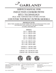
INSTALLATION AND
OPERATION MANUAL
GARLAND INDUCTION
SINGLE, MULTI-FUNCTIONAL
TABLE TOP UNITS,
MODELS: GMIU3.5 &
GMIU5.5
NITATION
SA
C
86037
FOR YOUR SAFETY:
DO NOT STORE OR USE GASOLINE
OR OTHER FLAMMABLE VAPORS OR
LIQUIDS IN THE VICINITY OF
THIS OR ANY OTHER
APPLIANCE
WARNING:
IMPROPER INSTALLATION, ADJUSTMENT,
ALTERATION, SERVICE OR MAINTENANCE
CAN CAUSE PROPERTY DAMAGE, INJURY,
OR DEATH. READ THE INSTALLATION,
OPERATING AND MAINTENANCE
INSTRUCTIONS THOROUGHLY
BEFORE INSTALLING OR
SERVICING THIS EQUIPMENT
LIS T E D
CM
CONFORMS TO UL-197 & NSF-4 CERTIFIED TO
CAN/CSA C22.2NO. 109 VDE EN60335-2-38.
PLEASE READ ALL SECTIONS OF THIS MANUAL
AND RETAIN FOR FUTURE REFERENCE.
THIS PRODUCT HAS BEEN CERTIFIED AS
COMMERCIAL COOKING EQUIPMENT AND
MUST BE INSTALLED BY PROFESSIONAL
PERSONNEL AS SPECIFIED.
INSTALLATION AND ELECTRICAL CONNECTION
MUST COMPLY WITH CURRENT CODES:
IN CANADA - THE CANADIAN ELECTRICAL
CODE PART 1 AND / OR LOCAL CODES.
IN USA – THE NATIONAL ELECTRICAL CODE
ANSI / NFPA – CURRENT EDITION.
Users are cautioned that maintenance and repairs must be performed by a Garland authorized service agent
using genuine Garland replacement parts. Garland will have no obligation with respect to any product that has been
improperly installed, adjusted, operated or not maintained in accordance with national and local codes or installation
instructions provided with the product, or any product that has its serial number defaced, obliterated or removed,
or which has been modified or repaired using unauthorized parts or by unauthorized service agents.
For a list of authorized service agents, please refer to the Garland web site at http://www.garland-group.com.
The information contained herein, (including design and parts specifications), may be superseded and is subject
to change without notice.
GARLAND COMMERCIAL INDUSTRIES
185 East South Street
Freeland, Pennsylvania 18224
Phone: (570) 636-1000
Fax: (570) 636-3903
Part##4020897
4520897(01/31/08)
(01/31/08)
Part
GARLAND COMMERCIAL RANGES, LTD.
1177 Kamato Road, Mississauga, Ontario L4W 1X4
CANADA
Phone: 905-624-0260
Fax: 905-624-5669
Enodis UK LTD.
Swallowfield Way, Hayes, Middlesex UB3 1DQ ENGLAND
Telephone: 081-561-0433
Fax: 081-848-0041
© 2004 Garland Commercial Industries,
Inc.
Page
Page Part # 4520897 (01/31/08)
TABLE OF CONTENTS
DIMENSIONS AND SPECIFICATIONS, . . . . . . . . . . . . . . . . . . . . . . . . . . . . . . . . . 4
Operation And Control. . . . . . . . . . . . . . . . . . . . . . . . . . . . . . . . . . . . . . . . . . . . . . . . . . . . . . . . . . . 5
Operation Conditions. . . . . . . . . . . . . . . . . . . . . . . . . . . . . . . . . . . . . . . . . . . . . . . . . . . . . . . . . . . . 5
INTRODUCTION . . . . . . . . . . . . . . . . . . . . . . . . . . . . . . . . . . . . . . . . . . . . . . . . . . . . 5
Application. . . . . . . . . . . . . . . . . . . . . . . . . . . . . . . . . . . . . . . . . . . . . . . . . . . . . . . . . . . . . . . . . . . . . . 5
Purpose of induction cookers. . . . . . . . . . . . . . . . . . . . . . . . . . . . . . . . . . . . . . . . . . . . . . . . . . . . .5
Description of products. . . . . . . . . . . . . . . . . . . . . . . . . . . . . . . . . . . . . . . . . . . . . . . . . . . . . . . . . . 5
INSTALLATION . . . . . . . . . . . . . . . . . . . . . . . . . . . . . . . . . . . . . . . . . . . . . . . . . . . . . 6
Location. . . . . . . . . . . . . . . . . . . . . . . . . . . . . . . . . . . . . . . . . . . . . . . . . . . . . . . . . . . . . . . . . . . . . . . . . 6
Installation Ambience. . . . . . . . . . . . . . . . . . . . . . . . . . . . . . . . . . . . . . . . . . . . . . . . . . . . . . . . . . . . 6
Clearances. . . . . . . . . . . . . . . . . . . . . . . . . . . . . . . . . . . . . . . . . . . . . . . . . . . . . . . . . . . . . . . . . . . . . . . 6
Electrical Connections . . . . . . . . . . . . . . . . . . . . . . . . . . . . . . . . . . . . . . . . . . . . . . . . . . . . . . . . . . . 6
OPERATION . . . . . . . . . . . . . . . . . . . . . . . . . . . . . . . . . . . . . . . . . . . . . . . . . . . . . . . . 7
Display. . . . . . . . . . . . . . . . . . . . . . . . . . . . . . . . . . . . . . . . . . . . . . . . . . . . . . . . . . . . . . . . . . . . . . . . . . 7
Function Test. . . . . . . . . . . . . . . . . . . . . . . . . . . . . . . . . . . . . . . . . . . . . . . . . . . . . . . . . . . . . . . . . . . . 7
Heating . . . . . . . . . . . . . . . . . . . . . . . . . . . . . . . . . . . . . . . . . . . . . . . . . . . . . . . . . . . . . . . . . . . . . . . . . 8
Comfort. . . . . . . . . . . . . . . . . . . . . . . . . . . . . . . . . . . . . . . . . . . . . . . . . . . . . . . . . . . . . . . . . . . . . . . . . 8
Cooking Process With Temperature Probe . . . . . . . . . . . . . . . . . . . . . . . . . . . . . . . . . . . . . . . . 8
Hold Function. . . . . . . . . . . . . . . . . . . . . . . . . . . . . . . . . . . . . . . . . . . . . . . . . . . . . . . . . . . . . . . . . . . 8
Pan Detection . . . . . . . . . . . . . . . . . . . . . . . . . . . . . . . . . . . . . . . . . . . . . . . . . . . . . . . . . . . . . . . . . . . 9
Control Of The Heating Area. . . . . . . . . . . . . . . . . . . . . . . . . . . . . . . . . . . . . . . . . . . . . . . . . . . . . .9
Out Of Operation. . . . . . . . . . . . . . . . . . . . . . . . . . . . . . . . . . . . . . . . . . . . . . . . . . . . . . . . . . . . . . . . 9
SAFETY CONCERNS . . . . . . . . . . . . . . . . . . . . . . . . . . . . . . . . . . . . . . . . . . . . . . . . . 9
Description Of Danger Signs . . . . . . . . . . . . . . . . . . . . . . . . . . . . . . . . . . . . . . . . . . . . . . . . . . . . . 9
Safety Conscious Work. . . . . . . . . . . . . . . . . . . . . . . . . . . . . . . . . . . . . . . . . . . . . . . . . . . . . . . . . . . 9
Operator/Operating Personnel Safety Information. . . . . . . . . . . . . . . . . . . . . . . . . . . . . . . . . 9
Unauthorized Reconstruction And Use Of Spare Parts. . . . . . . . . . . . . . . . . . . . . . . . . . . . 10
TROUBLE SHOOTING . . . . . . . . . . . . . . . . . . . . . . . . . . . . . . . . . . . . . . . . . . . . . . . 11
Error Messages . . . . . . . . . . . . . . . . . . . . . . . . . . . . . . . . . . . . . . . . . . . . . . . . . . . . . . . . . . . . . . . . . 11
Troubling Shooting Guide. . . . . . . . . . . . . . . . . . . . . . . . . . . . . . . . . . . . . . . . . . . . . . . . . . . . . . . 12
CLEANING AND SERVICING . . . . . . . . . . . . . . . . . . . . . . . . . . . . . . . . . . . . . . . . . 13
Cleaning. . . . . . . . . . . . . . . . . . . . . . . . . . . . . . . . . . . . . . . . . . . . . . . . . . . . . . . . . . . . . . . . . . . . . . . . 13
Support. . . . . . . . . . . . . . . . . . . . . . . . . . . . . . . . . . . . . . . . . . . . . . . . . . . . . . . . . . . . . . . . . . . . . . . . 13
Part # 4020897 (01/31/08)
Page DIMENSIONS AND SPECIFICATIONS,
5-3/8"
(138mm)
3-7/8"
(97mm)
removable
washable
airfilter
7-7/8"(198mm)
2-5/8"(65mm)
17-3/8" (440mm)
12-5/8" (320mm)
6'cord and plug
(208/240 volt, 60 cycle units only)
2-3/4"(70mm)
8-3/8"(210mm)
fresh air
view A: exhaust
12-5/8"(320mm)
5-7/8"
(144mm)
exhaust
15"(380mm)
Plug Configurations:
Electrical
Model
Characteristics
Plug
208V/60Hz/1Ø
GMUI-3.5
240V/60Hz/1Ø
GMUI-5.5
208V/60Hz/3Ø
Electrical Loading:
Model
Watts
208/60/1
208/60/3
240/60/1
230/50/1
400/50/3
440/60/3
GMIU‑3.5
3500
16 amp
N/A
14 amp
15 amp
N/A
N/A
GMIU‑5.5
5500
N/A
16 amp
N/A
N/A
9 amp
8 amp
Page Part # 4520897 (01/31/08)
DIMENSIONS AND SPECIFICATIONS, Continued
Operation And Control
Lamp operation 24V DC/max. 40mA (red)
Key pad and LED display
Operation Conditions
Max. Tolerance Of The Nominal
Supply Voltage
+6/-10%
Supply Frequency
50/60 Hz
Protection Class
Minimal Diameter Of The Pan
1P 43
5” (127mm)
INTRODUCTION
Application
Description of products
The following instructions contain information, which
is fundamentally important and must be taken into
account during assembly, operation and maintenance.
They must therefore read very carefully before installation
and operation by the responsible specialist staff and the
operator(s). They must always be available for consultation at
the place of operation.
We manufacture several basic types of induction cookers
with various performances and measurements. All are
built to last; they are also compact and powerful with a
revolutionary technology in a complete case of stainless
steel. All of our accessories are designed to coordinate with
the induction units and since each unit is equipped with
continuous control, they allow efficient cooking.
Purpose of induction cookers
Features include:
The Garland induction unit cookers are especially suitable
as cookers in the kitchen and for the preparation of meals
on the table. A cooker can be used for cooking, warming up,
keeping warm, flambéing, roasting, etc. The cookers are to
be used only with pans made of material which is suitable for
induction. There are specific manufacturers who sell special
types of pots and pans for induction cooking.
• Simple operation by key pad
DO NOT use induction cookers to heat up any other
metallic objects other than pots and pans provided for it.
• Short cooking time
• Power display with LED
• Compact powerful electronics enable flat construction
and safe operation
• A maximum of safety thanks to multiple safety functions
• Electronic checking
• Compact measurement – light weight
• Meets all current standards: VDE EN 60335-1/-2/36, CEconforming
• UL197; CAN/CSA/C22.2 No., 109, NSF 4-1996
Part # 4020897 (01/31/08)
Page INSTALLATION
Location
The cooker has to be set up on a stable place like a table.
It requires an area of at least 400 x 480 mm (15.7” x 18.9”).
The air inlet and air outlet must not be obstructed, the table
must be able to withstand a loading of 40 kg (88 lbs). The
cooker doesn’t have to be fixed on the table. The key pad
to operate the cooker must be easily accessible. It must be
set up in such a way that it cannot fall down or move in an
uneven position.
1. The induction unit is equipped with an additional grease
filter. Make sure that the induction unit does not take is
hot or grease laden air (concerns units standing side by
side, or one behind the other, or standing near a frying
pan or oven).
2. The induction unit must not be placed near or on a hot
surface.
3. The air intake temperature must be under 104°F (40°C).
5. The operating staff has to make sure that installation,
support and inspection is done by qualified personnel.
Installation Ambience
CONDITIONS
STORAGE
FUNCTION
Max. Ambient
Temperature
> -4°F(-20ºC) to
158°F(70ºC)
> 41ºF (5ºC) to
104ºF (40ºC)
Max. Relative
Humidity Of Air
> -10% to 90%
> 30% to 90%
Clearances
Induction Unit
Side View
d: minimum distance to the wall = 40 mm
d
Air Exit
Air Intake
Electrical Connections
Push “OFF” on the key pad before connecting the cooker with
the voltage supply.
The operator has to insure that all installation, maintenance
and inspection work is carried out by authorized and
qualified personnel.
1. Check and ensure that the supply voltage matches the
voltage given on the specification plate.
2. The electrical connections must satisfy local house
installation regulations. The valid national and local
regulations must be observed.
3. The cooker is provided with a cord and plug (60 cycle
units only).
There is a minimum clearance of 1.6” (40mm) from the back
wall.
This induction unit is equipped with an air cooling system.
Make sure that the air supply and air exhaust are not blocked
(wall, fabric etc).
Page Part # 4520897 (01/31/08)
OPERATION
Display
Your cooker must be positioned in a suitable place and
connected to a voltage supply. Make sure the cooker is well
positioned and free from exposure to vibration.
Make sure the unit is in the “OFF” position.
Remove all objects from the glass ceramic cooking zone,
verify if this area is neither cracked not broken. Don’t
continue with use when the glass ceramic cooking zone is
cracked or broken, immediately switch off and disconnect
the cooker from the outlet.
CAUTION The glass ceramic cooking zone is warmed up
from the heat of the pan. To avoid injuries (burning) do not
touch this area.
= Is actual value
With use of an external temperature probe
variables can be regulated infinitely.
= Actual temperature key with use of the temperature
probe,
/
the
Use a pan that is suitable for induction cooking, having a
bottom diameter of at least 127 mm (5 inches).
=Hold keeping warm facility.
= Cooking level “low, mid and high”, are
preprogrammed, but can be changed individually by
keys.
/
= On/Off key.
1. Put some water in the pan and place the pan in the center
of the heating area.
2. Push “ON” as well as a position between 1 and 12. The
indicator will illuminate lights (red) and the water will be
heated.
3. Take the pan away from the heating area, the indicator
light will flash.
4. Place the pan back on the heating area, the indicator light
will illuminate and the heating process will continue.
Function Test
Before carrying out function checks, the operator must know
how to operate the cooker.
Induction Unit
Surface View
5. Push “OFF”, the heating process will stop, indicator light
turns off.
The shining indicator light operation means that energy is
being transferred to the pan.
Heating Area
If the indicator operation remains off, check the following:
1. Is the cooker connected to the outlet?
2. Are the indicator lights “ON”?
Coil
3. Did you use a suitable pan (bottom diameter at least
127mm (5 inches), pan made of suitable material)?
4. Is the pan placed in the center of the heating area?
To verify if the pan is suitable, use a permanent magnet and
find out if it sticks to the bottom of the pan. If not, your pan
is not suitable for induction cooking. Choose a pan which is
recommended for induction cooking.
If in spite of all positive controls and tests the cooker doesn’t
work, refer to the Trouble Shooting Section.
Part # 4020897 (01/31/08)
Page OPERATION Continued
Heating
The induction cooker is immediately ready for operation by
pushing the “ON/OFF” key. The shining indicator operation
lights shows that energy is transferred to the pan. The power
ratings “low, mid and high” are fixed and can be changed
infinitely by pushing the
/ keys. The inductive power
depends on the power stage (LED indicator).
LED position 1 >
minimum power
LED position 12
>
maximum power
Temperature in °C
TEMPERATURE CURVE
88
86
84
82
80
78
76
74
72
70
68
66
64
62
60
58
56
54
Comfort
The cooker only transmits energy if a pan is
placed on the heating area, independently of the
position of the control knob. If you take the pan
away from the heating area, power transfer stops
immediately. If the pan is put back on the heating
are, the selected power will be transferred to the
pan again.
After switching the cooker to the OFF position the
cooking process will stop.
Cooking Process With Temperature Probe
You can use the temperature probe to set and control the
operation of the unit when cooking sauces, soups, creams etc.
Temperature control
1
2
3
Power Stages
4
5
6
7
8
9
10
11 12
Due to the following characteristics the operator must be
more attentive when using the induction cooker than would
be required with other appliances.
The heat storage capacity of this system is very low. If the
heating level is changed by pushing the / keys, the
food is immediately exposed to a different temperature. Do
not put empty pans on the glass ceramic cooking zone, first
put grease or liquid into the pan and start cooking process
after that. Empty pans and pots will heat up very quickly.
Adjust carefully the heating level to the required cooking
mode adjusting the temperature with / keys.
Page The pan should always remain in the center of the heating
area, otherwise the bottom of the pan is heated unequally
and the food inside the pan may burn. When heating oil or
grease, constantly check the pan to prevent oil and grease
from overheating and burning.
The temperature probe can be fixed with the holding device
at the pan and put into the liquid, then connect the probe
plug into the receptacle. You can now choose the required
temperature for cooking or keeping warm by using the
/ keys. Pressing on the temperature key will show the
actual temperature.
When finished with the temperature probe, disconnect
it completely and stop the induction unit by pressing the
“OFF/ON” key.
Hold Function
The hold function can be used as simple keeping warm
function. The temperature control is done by the sensing
element that is placed directly under the Ceran plate. You
can choose the required temperature by pressing on
/
keys.
Part # 4520897 (01/31/08)
OPERATION Continued
Pan Detection
Out Of Operation
During pan detection, the indicator operation flashes. No
power is transferred and the indicator lamp flashes if no pan
or an unsuitable pan is detected. Pans having a diameter
smaller than 127 mm (5”) are not detected.
If the cooker is out of operation make sure that the control
knob is in the “OFF” position. If you don’t use the cooker for
a longer period (several days) unplug the unit. Make sure
that no liquid can enter into the cooker and don’t clean the
cooker with a jet of water.
Control Of The Heating Area
The heating area is controlled with a temperature sensor.
Overheated pans (hot oil, empty pans) will be detected.
Energy transfer will be stopped. The induction unit must be
restarted after it has cooled down.
SAFETY CONCERNS
Description Of Danger Signs
This symbol identifies the safety
information which may cause
danger (personal injury) for people
at non-observance of proper
operation.
CAUTION
Indicates a hazard or unsafe
practice which could result in
minor personal injury or property
damage.
Information signs mounted directly on the cooker must be
observed at all times and kept in a fully legible condition.
EXAMPLE:
CAUTION Refer to instructions before operating or servicing
the unit.
Safety Conscious Work
The safety information contained in these instructions for
use, the existing national regulation for the prevention of
accidents as well as any internal working operating and
safety regulations stipulated by the operator must be
observed.
Part # 4020897 (01/31/08)
Certain risks may be associated with non-observance of
precautions, including:
1. Danger to persons through electrical causes.
2. Danger to persons through overheated pans.
3. Danger to persons through an overheated cooking
platform (ceran plate).
The operating reliability of the cookers can only be
guaranteed with proper use.
Operator/Operating Personnel Safety
Information
Any risks from electric power must be eliminated. The
induction unit shall only be used if the installation of the
electricity is fitted by an approved installation contractor in
accordance with specific national and local regulations.
The heating area is warmed up from the heat of the pan. To
avoid injuries (burning) do not touch the heating area.
1. To avoid overheating of pans by means of evaporating
the contents, don’t heat up pans unattended.
Page SAFETY CONCERNS Continued
2. Switch the control knob off it you take the pan away for a
while. This will avoid having the heating process continue
automatically when a pan is placed back on the heating
area. So, if any person starts to use the cooker, he/she will
have to start the heating process by turning the control
knob in the ON-position.
3. Do not insert any piece of paper, cardboard, cloth, etc.
between the pan and the heating area, as this might
initiate a fire.
4 As metallic objects are heated up very quickly when
placed on the operating heating area, do not place any
other objects (closed cans, aluminum foil, cutlery, jewelry,
watches etc.) on the induction cooker. Persons with a
pacemaker should ask their doctor whether they are safe
near an induction cooker or not.
5. Do not place credit cards, phone cards, cassette tapes,
or other objects that are sensitive to magnetism on the
Ceran plate.
6. The induction cooker has an internal air-cooling system.
Do not obstruct the air inlet-and air outlet-slots with
objects (cloth). This would cause overheating and
therefore the cooker would switch off.
Page 10
7. This induction unit is equipped with a grease filter, placed
at the bottom of the case. The grease filter is fixed on a
mounting with support angles and can be pulled out
from the operator’s side.
8. Make sure that this filter is cleaned in the dishwasher
once a week otherwise the air cooling system can not
work perfectly and this would lead to overheating the
unit.
9. Avoid liquid entering into the cooker. Do not let water or
food overflow the pan. Do not clean the Cooker with a jet
of water.
10.If the heating area (Ceran plate) is cracked or broken, the
induction cooker must be switched off and disconnected
from the electric connection. Don’t touch any parts inside
the cooker.
Unauthorized Reconstruction And
Use Of Spare Parts
Reconstruction of the cooker or changes to the cooker are
not allowed. Contact the manufacturer if you intend to
make any changes on the cooker. To guarantee the safety,
use only genuine spare parts and accessories authorized
by the manufacture. The use of other components voids all
warranties.
Part # 4520897 (01/31/08)
TROUBLE SHOOTING
CAUTION Do not open the cooker, dangerous electric
voltage inside
The cookers may only be opened by authorized service
personnel.
Stop any actions if the heating area (Ceran plate) is cracked
or broken, the induction cooker must be switched off and
disconnected from the electric supply. Don’t touch any parts
inside the cooker.
NUMBER OF FLASHING
SIGNALS – CODE
Error Messages
Order of error message: The indicator lamp “ON” flashes for
an interval of 0.6 sec. The number of the following short
flashes has to be counted and indicating the kind of error
corresponding to the following mentioned code system.
SIGNIFICATION
NOTES
--
No fault, normal operation
01
No spool current, Hardware overcurrent
02
High spool current, Software overcurrent
03
Temperature cooling plate
04
Temperature cooking platform, overheating
05
Power rotary switch line break
06
Raised inside temperature
07
Sensing element of cooking platform, short circuit
*
12
Power reduction cooling plate temperature
**
13
Power reduction cooking platform temperature
**
14
Power reduction caused by bad pan material
**
***
*
08
09
10
11
* The induction unit continues working but the temperature of the cooking platform is not
controlled anymore.
** The induction unit continues working with reduced power cycles.
*** Bad pan material.
Part # 4020897 (01/31/08)
Page 11
TROUBLE SHOOTING Continued
Troubling Shooting Guide
Fault
No heating indicator operation is OFF
(dark)
Possible Cause
Action to take through operator or
operating personnel
No electrical supply
Check if the electrical supply (cable
plugged in the wall socket), check
preliminary fuses
Control in off-position
Push control on
Pan too small (bottom diameter less
than 5” (127 mm )
Use a suitable pan
Pan is not placed in the center of the
heating area (the cooker can’t detect
the pan)
Move the pan to the center of the
heating area
Unsuitable pan
Choose a pan which is recommended
for induction cooking *
Cooker defective
Ask your supplier for repair service,
unplug the cooker from the electrical
supply
Used pan is not ideal
Use a pan which is recommended for
induction cooking, compare results
with ‘your’ pan
Air-cooling system obstructed
Verify, that air inlet and air outlet are
not obstructed with objects
Ambient temperature is too high (the
cooling system is not able to keep the
cooker in normal operating conditions
**
Verify, that no hot air is sucked in by the
fan. Reduce the ambient temperature.
The air inlet temperature must be lower
than 40ºC/110ºF
One phase is missing (only with three
phase supply)
Check preliminary fuses
Cooker defective
Ask your supplier for repair service,
unplug the cooker from the electrical
supply
No reaction to control knob positions
Control knob defective
Ask your supplier for repair service,
unplug the cooker from the electrical
supply
Heating cycle switches off and on
within minutes, fan is active
Air inlet or outlet obstructed
Remove objects from air inlet and air
outlet slots, clean the slots
Grease filter is dirty
Clean grease filter
Fan defective
Ask your supplier for repair service
Poor heating, indicator operation is ON
(shines)
Heating switches off and on within
minutes, fan is never active
Page 12
Fan control defective
Part # 4520897 (01/31/08)
TROUBLE SHOOTING Continued
Fault
Possible Cause
After a longer permanent operating
time, the heating switches off and on
within minutes
Coil overheated, cooking area too hot
Small metallic objects (e.g. Spoon) are
heated up within the cooking area
Pan detection tuned incorrectly
Empty pan
Action to take through operator or
operating personnel
Switch cooker off, remove pan and wait
until the cooking area has cooled off
Pan with overheated oil
Control logic board
* To verify if the pan is suitable, use a permanent magnet and find out if it sticks on the bottom of the pan. If not, your pan is
not suitable for induction cooking. Choose a pan which is recommended for induction cooking. Choose pan material suitable
for induction appliances.
** The cooling-system (fan) starts to operate when the heat temperature exceeds 55°C/130°F. At heat temperatures higher
then 70°C/160°F, the controller automatically reduces the power to keep the power unit in normal operating conditions. The
cooker runs in a non continuous mode. This mode can be heard.
CLEANING AND SERVICING
Cleaning
Support
Common types of soiling and recommendations how to treat
them:
Good maintenance of the induction cooker requires regular
cleaning, care and servicing. The operator has to ensure that
all components relevant to safety are in perfect working
order at all times.
Slight soiling, no burned residues
Wipe with a moist cloth (scotch), without cleaning agent
Lime deposits, caused by water which has boiled over
These spots can be removed with vinegar or a special
cleaning agent
Grease filter
The cooker has to be examined at least once a year by an
authorized technician.
CAUTION Do not open the cooker, dangerous electric
voltage inside.
The cookers may only be opened by authorized personnel.
Clean this filter once a week by putting it in the dishwasher
Make sure that no liquid can enter in the induction unit. Do
not clean the Cooker with a jet of water.
Part # 4020897 (01/31/08)
Page 13
Page 14
Part # 4520897 (01/31/08)
Part # 4020897 (01/31/08)
Page 15