1
Back
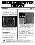
Installation Manual
COLOR SCANNING SONAR
FSV-30/FSV-30S
SAFETY INSTRUCTIONS................................................................................................i
SYSTEM CONFIGURATION..........................................................................................iii
EQUIPMENT LISTS ....................................................................................................... iv
1. MOUNTING THE EQUIPMENT................................................................................1-1
1.1 Hull Unit ................................................................................................................................1-1
1.2 Processor Unit ......................................................................................................................1-8
1.3 Control Unit...........................................................................................................................1-9
1.4 Transceiver Unit ..................................................................................................................1-12
1.5 Grounding the Equipment ...................................................................................................1-12
1.6 Installing the Attachment Flange (option)............................................................................1-13
1.7 Cable Extension Kit (option) ...............................................................................................1-14
1.8 Installing the Attachment Kit (option)...................................................................................1-15
2. WIRING ....................................................................................................................2-1
2.1 How to Use the Crimping Tool, Pin Extractor ........................................................................2-1
2.2 Wiring....................................................................................................................................2-2
2.3 Processor Unit .................................................................................................................... 2-4
2.4 Transceiver Unit ..................................................................................................................2-10
2.5 Cable Extension Kit ............................................................................................................2-14
2.6 Input Voltage and Fuses .....................................................................................................2-18
3. ADJUSTMENT AND CHECK ...................................................................................3-1
3.1 Hull Unit Check .....................................................................................................................3-1
3.2 Heading Adjustment..............................................................................................................3-5
3.3 Configuring Own Ship Mark ..................................................................................................3-7
3.4 Other SYSTEM Menu Items .................................................................................................3-9
3.5 CONE Board Setting in the Processor Unit.........................................................................3-13
3.6 DIP Switch Setting ............................................................................................................3-14
4. CONNECTING THE EXTERNAL INTERFACE CS-120A ........................................4-1
PACKING LISTS ......................................................................................................... A-1
OUTLINE DRAWINGS ................................................................................................ D-1
INTERCONNECTION DIAGRAMS ............................................................................. S-1
www.furuno.co.jp
The paper used in this manual
is elemental chlorine free.
・FURUNO Authorized Distributor/Dealer
9-52 Ashihara-cho,
Nishinomiya, 662-8580, JAPAN
Telephone : +81-(0)798-65-2111
Fax
: +81-(0)798-65-4200
All rights reserved.
Printed in Japan
A : DEC . 2003
F : DEC . 13, 2010
Pub. No. IME-13230-F
(TATA )
FSV-30/30S
*00014857415*
*00014857415*
* 0 0 0 1 4 8 5 7 4 1 5 *
SAFETY INSTRUCTIONS
DANGER
Keep away from moving
shaft of the hull unit.
Gears may cause injury.
WARNING
WARNING
Install the specified transducer tank
in accordance with the installation
instructions. If a different tank is to be
installed the shipyard is solely responsible for its installation, and it should
be installed so the hull will not be
damaged if the tank strikes an object.
The tank or hull may be damaged if the
tank strikes an object.
Do not open the cover
unless totally familiar with
electrical circuits and
service manual.
If a steel tank is installed on a wooden
or FRP vessel, take appropriate
measures to prevent electrolytic
corrosion.
High voltage exists inside the
equipment, and a residual
charge remains in capacitors
several minutes after the
power is turned off. Improper
handling can result in electrical shock.
Electrolytic corrosion can damage the
hull.
Turn off the power at the switchboard
before beginning the installation.
Fire or electrical shock can result if the
power is left on.
Do not install the equipment where it
may get wet from rain or water splash.
Be sure that the power supply is
compatible with the voltage rating of
the equipment.
Connection of an incorrect power supply
can cause fire or damage the equipment.
CAUTION
Ground the equipment to
prevent electrical shock and
mutual interference.
Water can cause fire or electrical shock, or
damage the equipment.
Be sure no water leaks in at the transducer installation site.
Water leakage can sink the vessel. Also
confirm that the transducer will not loosen
by ship's vibration. The installer of the
equipment is solely responsible for the
proper installation of the equipment.
FURUNO will assume no responsibility for
any damage associated with improper
installation.
i
CAUTION
Maximum speed while the transducer is
projected or being raised or lowered
is as below, to prevent damage to the
transducer.
Projected
Raising/
Lowering
1200 mm stroke Max. 18 kt Max. 15 kt
1600 mm stroke Max. 15 kt Max. 12 kt
Observe the following compass safe
distances to prevent interference to a
magnetic compass:
Standard
compass
Steering
compass
Processor Unit
1.55 m
1.05 m
Control Unit
0.20 m
0.15 m
Other equipment should be positioned at
least 7 m away from a magnetic compass.
ii
SYSTEM CONFIGURATION
VGA Monitor
CONTROL UNIT
FSV-3001
AD Converter
AD-10
Loudspeaker
Current
Indicator
Sub Monitor
Current
Indicator/Log
Echo Sounder,
Current Indicator,
other
PROCESSOR UNIT
Navigator 1
Gyrocompass
E/S Interface
VI-1100A
FSV-3002/3002S
Net Recorder
Navigator 2
VI-1100A
External
Interface CS-120A
(Note 1)
100/110/115/
220/230 VAC,
1φ, 50/60 Hz
TRANSCEIVER
UNIT
FSV-301
Net Sonde
Junction Box
CS-170
Cable for
Extension Kit
FSV-305-5 or
FSV-305-15
(incl. Junction
Box)
100/110/115/
220/230 VAC,
1φ, 50/60 Hz
Note 1: Power Kit FSV-2403 (option, installed in
processor unit) required to connect CS-120A.
VI-1100A
Net Sonde
220 VAC,
3φ, 50/60 Hz
HULL UNIT
Hull unit
Specifications
FSV-303
1200 mm stroke
FSV-303-R
FSV-304
FSV-304-R 1600 mm stroke
Standard
Local Supply
Option
iii
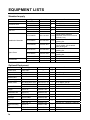
EQUIPMENT LISTS
Standard supply
Name
Control Unit
Type
FSV-3001
FSV-3002
FSV-3002S
FSV-301
FSV-303/303-R
FSV-304/304-R
Processor Unit
Transceiver Unit
Hull Unit
Installation Materials
Code No.
—
—
—
—
—
—
Qty
1
1
Accessories
With cable
For FSV-30
For FSV-30S
1
1
CP10-06000
000-144-389
1 set
CP10-06201
007-008-540
1 set
CP10-06100
000-067-067
SP10-03101
007-008-530
1 set
SP10-02601
006-921-340
1 set
SP10-02603
FP10-02901
FP10-02201
006-921-360
007-008-780
006-922-390
1 set
1 set
1 set
1 set
Spare Parts
Remarks
1200 mm stroke
1600 mm stroke
Signal cable 10S2078
(between transceiver unit and
hull unit, 8 m)
For transceiver unit. See
packing list.
For processor unit
CP10-04502, CP10-04506.
See packing list.
For transceiver unit. See
packing list.
For processor unit. See
packing list.
For processor unit
For processor unit
For control unit
Optional Equipment
Name
Control Unit
37-core Cable
E/S Interface
Net Sonde
Junction Box
Power Supply Kit
NMEA Cable
8-core Cable
Attachment
Flange
Attachment Kit
Loudspeaker
Installation
Materials
Cable Extension
Kit
Data Recording
Kit
Calibration Ball
iv
Type
FSV-3001
10S1258
VI-1100A
CS-170
Code No.
—
001-113-000-10
—
—
Qty
1
1
1
1
FSV-2403
MJ-A6SPF0012-100C
MJ-A6SPF0012-050C
VVS 0.3×8C *6M*
000-067-013
000-154-037-10
000-154-053-10
000-555-043
1
1
1
1
OP10-27
000-067-050
1
OP10-24
SEM-21Q
006-943-530
000-144-917
1
CP10-04801
006-934-240
1
FSV-305-5
FSV-305-15
000-067-072
000-067-073
1
OP10-31
000-017-095
1
OP10-33
OP10-34
000-017-096
000-017-097
1
1
Remarks
Specify length
For connection of CS-120A
10 m, NMEA, 6P-6P
5 m, NMEA, 6P-6P
6 m, for echosounder, 02S8040
See back of manual for details.
Junction box, 10S2240, 10S2144
Junction box, 10S2240, 10S2145
φ38.1
φ47.625
1. MOUNTING THE EQUIPMENT
NOTICE
Do not apply paint, anti-corrosive sealant
or contact spray to coating or plastic
parts of the equipment.
Those items contain organic solvents that
can damage coating and plastic parts,
especially plastic connectors.
1.1 Hull Unit
Note 1: The raise/lower control box on the hull unit contains a motion sensor. Therefore,
never drop the hull unit.
Note 2: Handle the transducer carefully. Shock will damage its sensitive components.
1.1.1 Mounting considerations
Decide the location of the hull unit through consultation with the dockyard and ship owner.
When deciding the location, the following points should be taken into account.
• Choose an area where propeller noise, cruising noise, air bubbles and interference from
turbulence are at a minimum. Generally, the point at 1/3 to 1/2 of the ship’s length from
the bow on or near the keel is optimum. On-the-keel installation is advantageous for
minimizing oil consumption in comparison with off-the-keel. If the hull unit can not be
installed on the keel, the center of the retraction tank should be within 600 mm of the keel
to prevent a rolling effect. For large ship with deep draft, the hull unit can be installed at
the bow.
1/2
1/3
Within 600 meter
Hull unit mounting location
• Choose a place where the hull bottom is flat and the draft is sufficiently deep. Normally,
the transducer should protrude at least 500 mm beyond the keel to minimize the effect of
air foam and bubbles.
• Choose a place where interference from other transducers is minimal. The hull unit
should be at least 2.5 m away from the transducers of other equipment.
1-1
• No obstacle should be in the fore direction since it causes a shadow zone and aerated
water, resulting in poor sonar performance.
• The physical distance between the hull unit and the transceiver unit should be no more
than 5 m.
• The space shown in the figure on the next page is required around the hull unit for wiring
and maintenance.
• If the ambient temperature around the unit will be below 0°C, provide the sonar
compartment with a heater to keep the temperature above 0°C.
650
650
650
1300
Maintenance space, example sonar compartment
Note: After mounting the equipment, install anti-vibration stays, referring to page 1-7.
1-2
1.1.2 Shortening the retraction tank
The retraction tank is 1300 mm in length when supplied. Shorten the tank as necessary so
that the transducer positions well below the keel when it is fully lowered. The following table
provides guidelines for shortening the tank. Refer also to the retraction tank installation
drawing at the back of this manual.
Installation
Method
D
XDCR Travel
1200 mm
stroke
1600 mm
stroke
D
Remove 280
Remove 280 - 290 mm
- 290 mm
from the bottom.
from the
Same as left. Note that the length
bottom.
"D" must be less than
1170 mm.
Same as left.
Remove less than
290 mm from the
bottom. Note that the
Same as left.
length "D" must be less
than 1570 mm.
Same as left.
Remove
less than
290 mm
from the
bottom.
Guidelines for shortening the retraction tank
Note 1: For the 1200 mm stroke hull unit, the transducer will not fully protrude unless the
tank is shortened by at least 280 mm from the bottom, and cannot be fully retracted
if more than 290 mm is removed.
Note 2: For the 1600 mm stroke hull unit, the transducer cannot be fully retracted if the tank
is removed more than 290 mm.
Note 3: When 290 mm is removed and “D” is minimum, the effect of air foam is minimized
because the transducer fully protrudes in water.
1-3
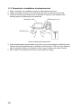
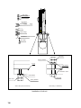
1.1.3 Remarks for installation of retraction tank
1. Make, if possible, the installation location a double bottom structure.
2. Install, if possible, the tank on the keel where the tank can be most firmly fixed.
3. Install the reinforcement ribs as near as possible to the top of the retraction tank,
allowing space for tightening of nuts and bolts.
Retraction tank
Reinforcement rib
250-300 mm
How to install reinforcement ribs
4. Add a doubling plate (a plate added to another to give extra strength or stiffness) at the
location where the retraction tank is welded to the hull bottom. The size of the doubling
plate is normally 1300 mm in diameter so that it may lie across two bottom frames.
5. Use a chisel to inscribe the bow mark on the attachment flange.
1-4
1.1.4 Installing hull unit on retraction tank
After welding the retraction tank and allowing sufficient time for cooling, install the hull unit
as follows:
1. Clean the hull unit flange, the O-ring and O-ring groove. Coat them with a slight amount
of grease. Place the O-ring in position on the tank flange.
2. Orient the hull unit so that the bow mark (inscribed) on its flange points toward the ship’s
bow. Note that heading adjustment is required if the bow mark is not facing the ship’s
bow.
3. Confirm that the O-ring is in position. Place the hull unit on the tank.
4. Coat every washer, nut and bolt with a slight amount of grease to ease removal. Fasten
the hull unit to the retraction tank with flat washers, spring washers and hex bolts.
5. Reinforce the hull unit against vibration by extending stays to the ship’s hull from the two
eye bolts at the top of the hull unit, referring to the procedure on page 1-7.
1-5
Hex. Nut
Spring Washer
Flat Washer
Bow Mark
Hull Unit Flange
O-ring
Tank Flange
Flat Washer
Hex. Bolt
Hex. Nut
Spring Washer
O-ring
Flat Washer
O-ring
Retraction Tank
Flat Washer
Hex. Bolt
Hex. Nut
Spring Washer
Stern side (seven locations)
Bow side (17 locations)
Installation of hull unit
1-6
1.1.5 Installing stays (anti-vibration measure)
Install stays from the top of the hull unit to the ship’s hull. The stays should be angle iron
with a size of 75×75×9 mm or more and at least two pieces should be used; one each to
ship’s bow and stern directions. Install if possible, two more stays in ship’s transverse
direction. This measure must be done to prevent damage to the transducer.
Bow
Stay
Stay
Hull Unit
Proper installation of stays
Do not install the stays on a crossbeam on an overhead. Vibration-resistance effect is
reduced since vibration is applied to the stays as rotation force. Install them horizontally.
Crossbeam
on overhead
(WRONG installation method)
Stay
Eye Bolt
PROPER installation
Hull Unit
90
Proper and improper stay installation methods
1-7
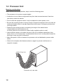
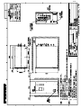
1.2 Processor Unit
Mounting considerations
When choosing a mounting location, keep in mind the following points:
• The processor unit must be mounted upright.
• Locate the unit out of direct sunlight and away from heat sources because of heat that
can build up inside the cabinet.
• Do not locate the equipment where it may be subjected to water splash or rain.
• Be sure the mounting location is strong enough to support the weight of the unit under the
continued vibration which is normally experienced on the ship. If necessary reinforce the
mounting location.
• Determine the mounting location considering the length of the cables below.
● Signal cable from the transceiver unit
● Control cable from the control unit (when locally supplied monitor is used)
• Leave sufficient space on the sides and rear of the unit to facilitate maintenance. Also,
leave a foot or so of "service loop" in cables behind the unit so it can be pulled forward for
servicing or easy removal of connectors.
• Make free space of 400 mm between the processor unit and bulkhead to prevent cable
stress.
• Observe the compass safe distances shown on page ii to prevent interference to a
magnetic compass.
Cable fixing hole
Processor unit, rear view
1-8
Mounting procedure
1. Unfasten two bolts from the bottom of the front side of the processor unit. Pull the unit
toward you to separate it from the mounting base.
2. Use six bolts (M6×20, supplied as installation material) to fix the mounting base.
3. Place the processor unit in front of the mounting base.
4. Push the unit forward until it touches the end of the mounting base.
5. Refasten two bolts removed at step 1 to fix the unit to the mounting base.
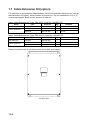
504
477
160+1
5.5
34
8
200+1 195+1
Front view
Top view
Processor unit
1.3 Control Unit
The control unit may be mounted on a tabletop with or without the KB (keyboard) fixing
plate (supplied), which mounts the control unit at an angle. If the control unit is not to be
fixed permanently, lay it atop the rubber feet (supplied as accessories). Be sure to observe
the compass safe distances noted on page ii to prevent interference to a magnetic
compass.
(1) Rubber feet
Attach four rubber feet to the bottom of the control unit if it is not going to be permanently
fixed.
1-9
(2) Mounting without KB fixing plate
1. Drill four mounting holes of 6 mm diameter to fasten the control unit, referring to the
outline drawing at the back of this manual.
2. Referring to the outline drawing for the control unit at the back of this manual, make a
cutout in the mounting location large enough to accommodate the name plate so the
control unit will lie flat.
3. Fix the control unit with four bolts (M5) from under the tabletop. (M5 bolts with a
sufficient length for the thickness of the tabletop should be provided locally.)
467±1
75 ±1 22
Fixing hole φ6
FSV-30
Control unit
(3) Mounting with KB fixing plate
1. To fix the control unit to a desired location at an angle, fasten the KB fixing plate to the
control unit and desired location with two upset screws (M5×10, supplied) and two
tapping screws (φ6.5, local supply) as below.
Upset screw (M5x10)
FSV-30
Tapping screw
( 6.5)
KB fixing plate
How to attach KB fixing plate
2. Set dust cover (supplied) to the control unit.
1-10
Passing the cable through the bottom of the control unit (for permanent mounting)
For permanent mounting methods (2) and (3), the control cable can be passed through the
bottom of the control unit as follows:
1.
2.
3.
4.
Unfasten eight screws (M4) to remove the cover from the bottom of the control unit.
Unscrew two screws (M4×10) to remove the cable clamp.
Disconnect two connectors J1 and J2 from the circuit board.
Attach the control cable to the control unit cover with the cable clamp (removed at step
2), two flat head screws (M4), flat washers, spring washers and nuts (hardware:
supplied).
Screw
M4x8 (8 pcs.)
Co
ntr
ol
un
it c
Clamp
ov
er
Previous cable hole
Nut
Spring washer
Flat washer
Screw (M4x12)
Fasten the cable with the clamp here.
Control unit, cover removed
5.
6.
7.
8.
Re-connect two connectors disconnected at step 3.
Fasten eight screws to attach the control unit cover.
Attach the connector seal (supplied) to the hole at the rear of the control unit.
Drill a hole of 30 mm in diameter to pass the cable from the bottom of the control unit
through the tabletop
9. Attach the connector seal (supplied) to the hole at the bottom of the control unit when
the above modification is not done.
10. Fix the control unit referring to (2) or (3) on the previous page.
Cable
Cable
Without KB fixing plate
With KB fixing plate
Control unit, side view
1-11
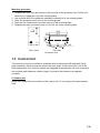
1.4 Transceiver Unit
The physical distance between the hull unit and the transceiver unit should be no more than
5 m. The transceiver unit should be mounted on a mounting base (shipyard supply) whose
dimensions are as shown in the outline drawing of the transceiver unit at the back of this
manual. Reinforce the transceiver unit against vibration by stays extending from the
eyebolts on the top of the unit. Fasten four bolts (M12, local supply) at the bottom of the
transceiver unit to fix the unit to the mounting location.
CHARGE
BV ERR
OV ERR
FUSE
Transceiver unit
1.5 Grounding the Equipment
Transceiver unit, junction box: Use copper strap (supplied).
Processor unit:
Use a ground wire (IV-8SQ).
Junction box for hull unit:
Use the wing bolt on the junction box.
1-12
1.6 Installing the Attachment Flange (option)
The attachment flange permits use of the tank for the CSH-20 series using the 1200 mm
stroke transducer.
Attachment flange Type: OP10-27, Code no: 000-067-050)
Name
Attachment flange
O-ring
Hex. nut
Flat washer
Spring washer
Type
10-077-5802
CO 0318A (V585)
M20 SUS304
M20 SUS304
M20 SUS304
Code No.
100-303-610
000-166-370-10
000-863-116
000-864-136
000-864-270
Qty
1
1
48
24
24
Remarks
Procedure
1. Clean the hull unit flange, O-ring and O-ring groove. Coat them with a slight amount of
grease.
2. Use 48 hex. nuts, flat washers and spring washers to fasten the attachment flange to
retraction tank.
3. Place the O-ring in position on the attachment flange.
To install the attachment flange and the hull unit, see paragraph 1.1.4.
Hex. Bolt
Flat Washer
Hull Unit Flange
O-ring
Flat Washer
Spring Washer
Hex. Nut
Attachment Flange
O-ring
Existing Tank
Flat Washer
Spring Washer
Hex. Nut
Attachment flange for 1200 mm stroke transducer, sectional view
1-13
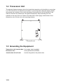
1.7 Cable Extension Kit (option)
For extension of the transducer cable between the hull unit and the transceiver unit, use the
cable extension kit (option), which includes a junction box. The kit is available in 5 m or 15
m extension lengths. Below are the contents of each kit.
Name: Cable Extension Kit, Type: FSV-305-5, Code No.: 000-067-072
Name
Junction box
Cable assembly
Type
Code No.
Qty
Remarks
FSV-305
10S2240
000-067-032
000-148-369-03
1
1
5m
10S2144
000-145-360
1
12.9 m
Name: Cable Extension Kit, Type: FSV-305-15, Code No.: 000-067-073
Name
Type
Code No.
Qty
Junction box
FSV-305
000-067-032
1
Cable assembly
10S2240
10S2145
000-148-370-03
000-145-361
1
1
Remarks
15 m
22.9 m
Fasten the junction box to a bulkhead with 4 bolts (M6, local supply).
Junction box
1-14
1.8 Installing the Attachment Kit (option)
The attachment kit permits use of the tank for the CSH-20 series using the 1600 mm stroke
transducer and FSV-243E/244E.
Attachment kit (Type: OP10-24, Code no.: 006-943-530)
Name
Insulation gasket (1)
Insulation gasket (2)
Type
MS-1000-67
MS-1000-68
Code No.
000-857-220
000-857-221
Qty
24
24
1. Clean the hull unit flange, the O-ring and O-ring groove. Coat them with a slight amount
of grease. Place the O-ring in position on the tank flange.
2. Lay the insulation gasket (1) on the top of the tank flange.
3. Orient the hull unit so that the bow mark (inscribed) on its flange points toward the ship’s
bow. Note that heading adjustment in the monitor is required if the bow mark does not
face the ship’s bow.
4. Confirm that the O-ring and the insulation gasket (1) are in position.
5. Place the hull unit on the tank.
6. Seven of the 24 bolt holes on the hull unit flange have already been fitted with bolts
(stern side). Insert the insulation gasket (2) into the bolt holes of the tank flange to which
these seven bolts are fitted.
7. Coat every bolt, washer and nut with a slight amount of grease to ease removal. Fit the
insulation gasket (2) into the bolt holes of the tank flange. Fasten the hull unit to the
retraction tank with insulation gasket (2), flat washers, spring washers and hex bolts.
8. Reinforce the hull unit against vibration by extending stays to the ship’s hull from the two
eye bolts at the top of the hull unit, referring to the figure at the top of page 1-8.
1-15
Hex. nut
Spring washer
Flat washer
Flange of hull unit
Flange of hull unit
O-ring
O-ring
Insulation gasket (1)
Insulation gasket (1)
Insulation gasket (2)
Insulation gasket (2)
Flat washer
Spring washer
Flat washer
Hex. nut
Hex. bolt
Spring washer
O-ring
Flat washer
O-ring
Insulation gasket
Retraction tank
Insulation gasket (2)
Flat washer
Hex. bolt
Hex. nut
Spring washer
Bow side
(17 locations)
Stern side
(Seven locations)
Installation of attachment kit
1-16
2. WIRING
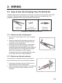
2.1 How to Use the Crimping Tool, Pin Extractor
A special crimping tool is necessary for connection of wires to the contact pins of the 38P
connector. The pin extractor removes the contact pin from the connector body. This
paragraph describes how to crimp and extract the contact pin.
Crimping Tool
06-1001-016
Pin Extractor
06-1877-04
(000-519-595)
Contact Pin
60-8017-0313-00-339
(000-519-542)
Crimping tool, contact pin, pin extractor
2.1.1 How to use the crimping tool
1. Remove the vinyl sheath by 3 to 4 mm to expose
the core.
2. Hold the crimping tool horizontally and insert the
contact pin with its slit facing downward into the
crimp hole on the crimping tool.
3. Insert the wire onto the contact pin and squeeze
the handle until the rachet releases. (The wire
should be placed deep enough into the contact pin
so that its end comes in contact with the stopper
plate of the crimping tool.) With crimping
completed, pull the wire while holding the contact
pin to make sure that it is tightly fastened.
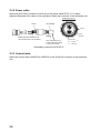
2.1.2 How to use the pin extractor
If a contact pin is inserted into an incorrect hole on
the connector body, remove it with the pin extractor.
1. Push the pin extractor into the pin hole from the
side opposite to the pin inserting side.
2. Push in the head of the pin extractor. The retaining
spring comes free and the contact pin can be
removed.
2
1
2-1
2.2 Wiring
10S2077 (10 m)
FSV-30
CONTROL UNIT FSV-3001
Monitor
(Local supply)
Transceiver
unit
Control unit
Monitor cable
(Local supply)
Control unit
External
monitor
*1
10S1258-1
Processor unit clamp
DPYCY-1.5 *2
*1: If connector may loosen by
vibration monitor cable may also
be connected inside.
PROCESSOR UNIT
FSV-3002/3002S
100/110/115/
220/230 VAC
1φ, 50/60 Hz
TRANSCEIVER UNIT
FSV-301
10S2078 (8 m)
*3
*4 *5
DPYCYS-2.5 *2
100/110/115/
220/230 VAC
1φ, 50/60 Hz
220 VAC
3φ, 50/60 Hz
TPYCY-4 *2
HULL UNIT
FSV-303
(1200 mm stroke)
FSV-304
(1600 mm stroke)
10S2223 (14.6 m)
*4 *5
*2: Japan Industrial Standard cable
*3: The same type of connector is fitted at each end, however the connector where the amount of sheath
removed is greater should be connected to the transceiver unit.
*4: When running the cables of 10S2078, 10S2223 refer to next page.
*5: When using cable for extension kit, the length of the cable between the transceiver unit
and the hull unit is 5 m or 10 m.
Wiring
2-2
Transceiver unit side
P2
(40 pin)
P1
(34 pin)
0.38 m
0.07 m
0.6 m
Clamp point
Clamp point.
10S2223
14.6 m
14.0 m
7.2 m
Hull unit side
10S2078
8m
Clamp point
0.07 m
0.28 m
Raise/lower control box
of the hull unit side
Note that the amount of cable inside the cable clamp on the cable between the hull unit and
transceiver unit may be shorted depending on cable length.
2-3
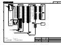
2.3 Processor Unit
Cables (10S2074, 10S1258-1 and control cable) from the various units are connected to the
CONE Board (10P6905) in the processor unit.
NOTICE
Divide cables attached to the back of the
processor unit between right and left side.
Tie each group with a cable tie at the
position 15 cm from connectors.
This is necessary to prevent cable stress.
15 cm
Cable tie
Processor unit, rear view
2.3.1 10S1258-1 cable
This cable runs between the processor unit and transceiver unit.
Shield
Anticorrosive Sheath
1. BLK
2. BLK/BRN
3. BLK/RED
4. BLK/ORG
5. BLK/YEL
6. BLK/GRN
7. BLK/BLU
8. BLK/PPL
19 8 9
10
18 7 2 3 11
1 4
17 6
12
5
13
16
15 14
Armor
9. BLK/GRY
10. BLK/WHT
11. BRN/RED
12. BRN/ORG
13. BRN/YEL
14. BRN/GRN
15. BRN/BLU
16. BRN/PPL
1:
Coaxial cable
2 to 19: Twisted pair cable
Cable type 10S1258-1, sectional view
2-4
17. BRN/GRY
18. BRN/WHT
19. RED/ORG
Fabrication of connector 00-8016-038-313761HV (CN-A101)
320
45
40
Shield
Vinyl Sheath
Core
Anticorrosive
Sheath
Armor
Insulating Tape
After exposing cores,
wind shield around the armor.
Fabrication of cable for connector 00-8016-038-313761HV
Guide Pin A
Guide Pin B
Position No.
Guide Pin A
(Large)
Guide Pin B
(Small)
Assembling 38P connector
Positioning guide pins
Guide pins of the connector identify the mating receptacle. They are;
• Guide pin A (Large): 1
• Guide pin B (Small): 1
2-5
2.3.2 Power cable
Attach the NCS-253-P connector (CN-A110) to the power cable DPYCY-1.5 (Japan
Industrial Standard (JIS) cable) or the equivalent. Attach the connector to the processor unit.
Cable DPYCY-1.5
Armor
Vinyl sheath
Armor
Solder lead wire to armor and
connect it to #1 pin of connector.
Vinyl
sheath
Taping
Use cable DPYCY-1.5
(Japan standard cable)
or equivalent cable.
Conductor
2
S = 1.5 mm
∅ = 1.56 mm
Assembling connector NCS-253-P
2.3.3 Control cable
Attach the control cable (10S2074 or 10S2075) to the CN-A103 connector in the processor
unit.
2-6
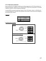
2.3.4 Optional equipment
With connection of a navigator and electronic fishing equipment, the FSV-30 provides true
motion presentation, target lock, echo sounder picture, FNZ marker presentation, and digital
indication of position, water temperature and depth.
Use the SRCN connectors (optionally supplied, Type: CP10-4801, Code no.: 006-934-240)
to connect equipment to the rear of the processor unit. Refer to the interconnection diagram
at the back of this manual.
Cable list
Outline of core
Simple
w/shield
Twisted
Sectional view of cables
02S8040
9 mm
Shield
No.
Color
1 WHT/BLU
2
BLK
3
PNK
4
GRN
5
ORG
6
YEL
7
RED
CO-SPEVV-SB-C 0.2sq, 5P
Shield
14 mm
No.
1
2
3
4
5
Color
YEL/BLK
YEL/WHT
YEL/RED
YEL/BLU
YEL/GRN
Armor
2-7
J5 (CIF1)
J7 (GYRO)
J8 (LOG)
J10 (FNZ)
J13 (EXT-KP)
Cable with armor
: SRCN6A13-5P
: SRCN6A16-10P
: SRCN6A13-3P
: SRCN6A21-10P
: SRCN6A21-10S
8 cm
2 cm
1 cm
Armor
Shield
3 mm
Vinyl sheath
Clamp fixing screw
Solder unused cores and
earth to braided shield.
Clamp
Solder earth wire.
Set screw
Wind shield
tape.
Connector case
Soldering side
Wind vinyl tape.
Attach conector at
shield to ground.
J9 (ES1)
: SRCN6A16-7P
J12 (ES2/NET) : SRCN6A16-10P
Cable without armor
2 cm
3mm
Shield
Vinyl sheath
Solder unused cores and
earh wire to braided shieeld.
Clamp fixing screw
Clamp
Set screw
Vinyl sheath
Wind vinyl tape
Connector case
Soldering-side
2-8
Synchronizing with echo sounder or other sonar
To synchronize the transmission of the FSV-30 with an echo sounder or other type of sonar,
make connections as shown below.
For current driven KP input
Processor EXT-KP
unit
KP signal
EXT-KP-IN-H 8
EXT-KP-IN-C 9
E/S
Sonar
For voltage driven KP (12 V) input
Processor EXT-KP
unit
KP signal
EXT-12VKP-H 10
0V 7
E/S
Sonar
Voltage driven KP output
Processor
unit
KP signal
EXT-KP
INTKP1
GND
INTKP2
GND
INTKP3
GND
1
2
3
4
5
6
E/S,
Sonar,
Current
indicator
Menu setting
See EXT KP INPUT on page 3-9.
2-9
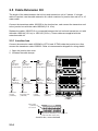
2.4 Transceiver Unit
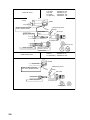
2.4.1 Fabrication of connector 00-8016-038-313761HV (CN-B101)
400
45
40
Shield
Vinyl Sheath
Anticorrosive
Sheath
Armor
Core
Insulating Tape
After exposing cores,
wind shield around the armor.
Fabrication of cable for 00-8016-038-313761HV
Shorten the unused wires appropriately and treat their ends with vinyl tape to prevent short
circuit.
Guide Pin A
Guide Pin B
Position No.
Guide Pin A
(Large)
Assembling 38P connector
Positioning guide pins
Use the tool shown below to position guide pins.
Connector
Tool
CN-B101
Guide Pin
2-10
Guide Pin A (large)
1
Guide Pin B (small)
1
Guide Pin B
(Small)
13-L
CN-B210
CN-B209
CN-B208
CN-B207
CN-B206
CN-B205
CN-B204
CN-B203
CN-B202
CN-B201
6962
6963
CN-B101
16-L
VH-3P
CN-B102
TRX-10
TRX-9
TRX-8
TRX-6
TRX-7
TRX-5
TRX-4
TRX-3
TRX-2
TRX-1
SB-1909
SB-1909
EDS3
05-L
EDS3
07-L
EL9P
SM18P
J202
J203
SM4P
EDS3
EL12P
J201
SM8P
SM12P
EL3P
J204
J205
J206
J601
F601
5A
F602
MAIN
I
5A
MAINTENANCE
Maintenance
Use Only.
(Should be OFF
for Normal
operation.)
INPUT
TB-B101
I
100/110/115
/220/230 VAC
:15A
50/60Hz
1
J301
J302
S603
H
YL8P
SM12P
2
J303
S604
H
S605
H
TB-B101
EL4P
15A
15A
INPUT(TB-B101) S603
100V
L
110V
H
115V
H
220V
H
230V
H
L
L
S604
L
L
H
L
H
S605
L
L
L
H
H
L
To Processor Unit
(cable 10S1258-1)
To Hull Unit
(cable 10S2078)
To Power Source
Transceiver unit, inside view
2-11
2.4.2 Fabrication of power cable type DPYCYS-2.5 (TB-B101)
Fabricate the cable DPYCYS-2.5 as below for connection to the power source.
Cable DPYCYS-2.5
Armor
Vinyl
sheath
Conductor
S = 4 mm 2
∅ = 2.55 mm
140
35
30
FV2-4 (2 pcs)
Anticorrosive
sheath
Amor
Vinyl sheath
Fabrication of cable type DPYCYS-2.5
2.4.3 Hull control cable (10S2078)
Connect the hull control cable (10S2078) to the CN-B102 in the transceiver unit.
Note: The same type of connector is fitted at each end, however the connector which has a
larger portion of its sheath removed should be connected to the transceiver unit.
2-12
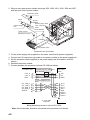
2.4.4 Wiring in transceiver unit
1. Open the transceiver unit cover.
2. Plug the P1 and P2 connectors at the end of signal cables into the proper receptacles in
the transceiver unit, referring to the interconnection diagram at the back of this manual.
3. Lead the signal cables into the transceiver unit appropriately.
4. Fasten the cables with cable clips after wiring the hull unit.
From right to left B201 to B210
P2
(40 pin)
13-L
P1
(34 pin)
CN-B210
CN-B209
CN-B208
CN-B207
CN-B206
CN-B205
CN-B204
CN-B203
CN-B202
CN-B201
6962
6963
VH-3P
16-L
TRX-10
TRX-9
TRX-8
TRX-6
TRX-7
TRX-5
TRX-4
TRX-3
TRX-2
TRX-1
SB-1909
SB-1909
EDS3
EDS3
07-L
Cable clip
05-L
10S2223
EL9P
SM18P
J202
J203
SM4P
EDS3
EL12P
J201
SM8P
SM12P
EL3P
J204
J205
J206
J601
F601
5A
F602
MAIN
I
5A
MAINTENANCE
Maintenance
Use Only.
(Should be OFF
for Normal
operation.)
INPUT
TB-B101
I
100/110/115
/220/230 VAC
:15A
50/60Hz
1
J301
J302
2
J303
S603
H
S604
H
S605
H
EL4P
SM12P
YL8P
15A
INPUT(TB-B101) S603
100V
L
110V
H
115V
H
220V
H
230V
H
15A
L
L
S604
L
L
H
L
H
S605
L
L
L
H
H
L
Secure
here with
metal clamp.
Fix signal cables with clamp.
Transceiver unit
Cable
number
10
9
8
7
6
5
4
3
2
1
Transceiver unit, top view
2-13
2.5 Cable Extension Kit
The length of the cable between the hull unit and transceiver unit is 5 meters. If a longer
cable is required, use the cable extension kit, which consists of a junction box and a 5 or 15
meter cable.
Connect the transducer cable 10S2223 to the junction box, and connect the transceiver unit
to the junction box with the cable 10S2240 (5 or 10 m).
Replace the cable (10S2078, 8 m) connected between the hull unit and transceiver unit with
the cable 10S2144 (12.9 m) or 10S2145 (22.9 m). Those cables are supplied with the
extension cable kit.
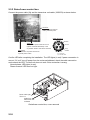
2.5.1 Junction box
Connect the extension cable 10S2240 to JCTN1 and JCTN2 inside the junction box. Also,
connect the transducer cable 10S2223. Refer to interconnection diagram for wiring details.
1. Open the junction box cover.
2. Unfasten the cable clamps.
P1
P3
Connect to
the J20 in
JCTN1 Board
P3
P1
Connect to
the J2 in
JCTN1 Board
Connect to
the J19 in
JCTN1 Board
JCTN1
Board
Connect to
the J1 in
JCTN1 Board
J1
J20 J19
J2 J1
J20 J19
J2 J1
J1
P2
Connect to
the J20 in
JCTN2 Board
Cable from
hull unit
(10S2223)
P2
Connect to
the J2 in
JCTN2 Board
P4
Connect to
the J19 in
JCTN2 Board
Cable from
transceiver unit
(10S2240)
Cable from
hull unit
(10S2223)
JCTN2
Board
P4
Connect to
the J1 in
JCTN2 Board
CSK
clamp
Cable from
transceiver unit
(10S2240)
Cable clamp
Signal cables
(10S2223)
from hull unit
Junction box
10 9
8 7
6
10 9 8 7 6
5
5
4
3 2 1
4 3 2 1
Signal cables (10S2240) from transceiver unit
("JUNCTION BOX" display side)
Junction box, cover removed
2-14
3. Lead in cable thru the appropriate location on the cable clamp and fix cable with
appropriate CKS clamp. Connect each cable to circuit board as shown in the figure on
the previous page.
Signal cable (10S2240) connects to “JUNCTION BOX” display side.
4. Lay the shield of each cable in the cable clamp.
5. Fasten the cable clamps.
2-15
2.5.2 Raise/Lower control box
Connect the power cable (3φ) and the transceiver unit cable (10S2078) as shown below.
CN-C101
Connect the transceiver
cable (10S2078) here.
Cable TPYCY-4
Sheath
TB-C101
Connect the power cable TPYCY-4
(Japan Industrial Standard) or the
equivalent cable to this terminal board.
LED (Red)
For detection of phase reversal on
3 phase power cable
Armor
Vinyl
sheath
Conductor
S = 4 mm2
∅ = 2.55 mm
Confirm LED after completing the installation. The LED lights (in red) if power connection is
correct. If it is off, turn off power from the mains switchboard, check the cable connection
and recheck the LED. The hull unit does not work if this connection is wrong.
Normal phase: LED lights (in red).
Phase reversal: LED does not light.
Power cable (3φ)
TPYCY-4
Cable from
transceiver unit
10S2078
Raise/lower control box, cover removed
2-16
100
25
20
M4(yellow) x 3
FV5.5-4
Vinyl
sheath
Sheath
Armor
(Clamp here by cable clamp.)
Power cable fabrication
2-17
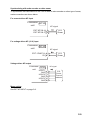
2.6 Input Voltage and Fuses
The transceiver unit is shipped from the factory with its input voltage set for 230 VAC and a
10 A fuse inserted in F601 and F602. For other voltages, change toggle switch positions
and fuses as below.
Input voltage
Set the toggle switches S603, S604 and S605 according to input voltage, referring to the
table below.
Input
(TB-B101)
100 V
110 V
115 V
220 V
230 V
S603
S604
S605
L
H
H
H
H
L
L
H
L
H
L
L
L
H
H
Default setting
Default setting
Fuses
Change the fuse in F601 and F602 according to input voltage, referring to the table below.
Input
(TB-B101)
100 V
110 V
115 V
220 V
230 V
Fuse
F601
F602
20A
20A
10A
10A
Default
setting
WARNING
Use the proper fuse.
Default
setting
Use of a wrong fuse can result in damage
to the equipment or cause fire.
Marking the label
After setting toggle switches and changing the
fuses, mark the voltage which applies on the label
on the inside of the cover. In the example shown
right, 100 V is marked so 20A fuses must be used.
FUSE
FUSE
F601
F602
INPUT
(TB-B101)
FUSE
F601 F602
100V
110V
115V
220V
230V
2-18
20A
20A
10A
10A
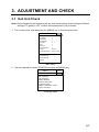
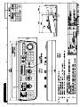
3. ADJUSTMENT AND CHECK
3.1 Hull Unit Check
Note: Before conducting this check (at the dry dock) transmission must be stopped. Default
setting of TX power is OFF. Confirm that transmission is off as follows:
1. Turn on the power, and then press the [MENU] key to show the main menu.
MENU
TX PULSE LENGTH-H
TX POWER-H
TVG-NEAR-H
TVG-MEDIUM-H
TVG-FAR-H
AGC-H
2ND AGC-H
ECHO AVERAGE-H
COLOR-H
COLOR RESPONSE-H
QUIT
:9
:9
:0
:0
:0
:0
:0
:0
: COLOR 1
: COLOR CURVE 3
H-SCAN SETTING...
V-SCAN SETTING...
OTHERS...
Main menu
2. Use the trackball to choose OTHERS and press the [MENU] key.
MENU
QUIT
OTHERS
QUIT
ES1 SETTING...
ES2 SETTING...
ERASE MARKS...
DISPLAY SETTING...
ALARM & AUDIO...
PRESET, MEMORY CARD...
INITIAL SETTING...
OTHERS menu
3-1
3. Choose INITIAL SETTING and press the [MENU] key.
CAUTION
YES
THIS ITEM IS DEFINED AS NONCHANGEABLE ITEM, ARE YOU
SURE TO CHANGE IT TO CHANGEABLE ?
NO
4. Choose YES and press the [MENU] key.
MENU
QUIT
OTHERS
QUIT
INITIAL SETTING
QUIT
MARK DISPLAY...
MARK SIZE...
DATA DISPLAY...
CURRENT VEC & WIND...
NET SONDE SETTING...
NET SHOOT SETTING...
TARGET LOCK...
STABILIZATION...
TEST...
INITIALIZATION...
INITIAL SETTING menu
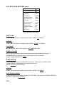
5. Choose TEST and press the [MENU] key.
MENU
QUIT
OTHERS
QUIT
INITIAL SETTING
QUIT
TEST
QUIT
BOARD TEST...
PANEL TEST...
TEST PATTERN...
RX TEST...
NOISE TEST...
TX
: OFF
TEST menu
6. Choose TX and press the [MENU] key.
7. Choose OFF (if it is not already selected) and press the [MENU] key.
8. Choose QUIT at the top of the menu screen and press the [MENU] key.
3-2
How to check the hull unit
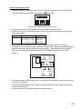
1. Press the POWER (|) switch on the control unit to turn on the equipment. Confirm that
“ ON” lamp above the POWER switch and theª switch light.
Transducer switches of the control unit
2. Confirm that the 5V and UP lamps on the raise/lower control box are lit.
3. Remove the cover of the raise/lower control box and use a multimeter to measure the
following voltages:
Terminal
TB-C101
Terminal No.
(1) – (2), (6) – (7)
(2) – (3), (7) – (8)
(1) – (3), (6) – (8)
Voltage
220 VAC
220 VAC
220 VAC
4. In the raise/lower control box, set the TEST/NORMAL switch to TEST. Press the
[DOWN] switch to confirm that the transducer lowers. Also, while the transducer is being
lowered, check that the MD LED lights when the MD L. SW kicks. Note that the MD L.
SW does not stop the transducer when the TEST/NORMAL switch is in the TEST
position.
TEST
OFF
NORMAL
5V
L.SW
UP MD DN
UP
DOWN
Control unit (in hull unit)
5. Press and release the [DOWN] switch. Confirm that the transducer stops at the moment
the switch is released.
6. Press the [DOWN] switch again. Confirm that the transducer stops at the moment the
lower limit switch kicks.
7. Confirm that the [UP] switch operates in a similar manner.
3-3
8. Check that LEDs on the panel of the raise/lower control box light as follows:
1) UP, MD and DN LEDs light when corresponding limit switch is kicked.
2) UP and DOWN LEDs light while UP and DOWN switches are pressed and extinguish when
the switches are released.
3) Set the TEST/NORMAL switch to NORMAL.
9. At the control unit, press the ª (mid position) switch. Confirm that the lamp above the
switch blinks while the transducer is being lowered, a short beep sounds when the mid
limit switch kicks, and the lamp lights when the transducer is lowered to the mid position.
10. Press the ª switch. Confirm that the lamp above the switch blinks while the transducer
is being lowered, a short beep sounds when the mid limit switch is kicked, and the lamp
lights when the transducer is fully lowered.
11. Press the © switch. Confirm that the lamp above the switch blinks while the transducer
is being raised, a short beep sounds when the mid limit switch is kicked, and the lamp
lights when the transducer is fully raised.
12. Press the OFF switch. Confirm that the transducer is completely retracted and then the
power is turned off.
13. With the transducer lowered (mid or fully lowered), confirm that the transducer is raised
when © or OFF is pressed.
3-4
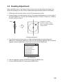
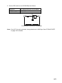
3.2 Heading Adjustment
When the BOW mark on the flange of the hull unit cannot be directed toward ship’s bow,
adjust the heading so an echo which is dead ahead appears dead ahead on the display.
1. Referring to the previous section, set the TX (transmission) to ON.
2. Locate a target in the bow direction (buoy, for example) and display it on a near range. If
the target appears at 12 o’clock the heading alignment is correct. If it does not, measure
the error and go to step 2.
Buoy
If target's on-screen
position is right of ship's
bow for example, heading
is skewed left.
Heading adjustment
3. Turn off the power and then turn it on again while pressing and holding down the
[MENU] key. Release the [MENU] key after the self-test screen appears. After the picture
appears, press the [MENU] key three times to open the SYSTEM menu.
SYSTEM MENU
QUIT
INTERFACE SETTING..
EXT DATA SETTING..
OWN SHIP MARK..
TEST&INITIALIZATION..
TX/RX SETTING..
TX/RX SETTING - H..
TX/RX SETTING - V..
OTHERS..
SYSTEM menu
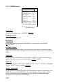
4. Use the trackball to choose OTHERS and press the [MENU] key.
5. Choose HEADING ADJUST and press the [MENU] key.
3-5
MENU
QUIT
OTHERS
QUIT
LANGUAGE
: ENGLISH
HEADING ADJUST
:0
ES2 SELECT
: ES
QUIT
CANCEL
ES DRAFT OFFSET : 0.0 m
EVENT KEY
: EVENT
AUTO TILT
: WIDE
SELECT USER PROG
: H/V INTERLOCK
TRACKBALL SPEED : NORMAL
HULL UNIT STROKE : 1200mm
OTHERS menu, HEADING ADJUST
6. Choose ▲ or ▼ to choose direction (plus or minus, respectively) in which to increment
or decrement setting and then press the [MENU] key to set. Each pressing of the
[MENU] key changes the setting in increments of 1°. The setting range is -180° to +179°.
7. Choose QUIT to finish the adjustment and press the [MENU] key.
8. Choose QUIT at the top of the menu screen and press the [MENU] key to close all
menus.
3-6
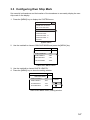
3.3 Configuring Own Ship Mark
Set own ship’s dimensions and the location of the transducer to accurately display the own
ship mark on the display.
1. Press the [MENU] key to display the SYSTEM menu.
SYSTEM MENU
QUIT
INTERFACE SETTING..
EXT DATA SETTING..
OWN SHIP MARK..
TEST&INITIALIZATION..
TX/RX SETTING..
TX/RX SETTING - H..
TX/RX SETTING - V..
OTHERS..
System menu
2. Use the trackball to choose OWN SHIP MARK and press the [MENU] key.
MENU
QUIT
OWN SHIP MARK
SHIP'S LENGTH
: 75m
SHIP'S WIDTH
: 20m
TD POSITION 1
: 15m
TD POSITION 2
: 0.0m
QUIT
OWN SHIP MARK menu
3. Use the trackball to choose SHIP’S LENGTH.
4. Press the [MENU] key to show the setting window.
MENU
QUIT
OWN SHIP MARK
SHIP'S LENGTH
: 75m
SHIP'S WIDTH
: 20m
TD POSITION 1
: 15m
TD POSITION 2
: 0.0m
QUIT
QUIT
CANCEL
OWN SHIP MARK menu, setting window
3-7
5. Choose ▲ or ▼ and then operate the [MENU] key to set the ship’s length (15 to 150 m).
6. Choose QUIT to finish the setting.
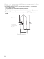
7. Set the SHIP’S WIDTH (5 to 30 m), TD POSITION 1 (5 to 50 m) or TD POSITION 2
(-10.0 to 10.0 m) similarly.
TD POSITION 1: Set the transducer’s distance from the bow.
TD POSITION 2: Set the transducer’s distance from the keel. Choose [+] for starboard,
[-] for port.
8. Choose QUIT at the top of the menu screen and press the [MENU] key to close all
menus.
TD Position 1
Ship's
Length
TD Position 2
(Negative value
for port)
Ship's Width
Ship shape description
3-8
3.4 Other SYSTEM Menu Items
This section mainly shows you how to set up according to external equipment connected.
Default settings are underlined.
3.4.1 INTERFACE SETTING menu
MENU
QUIT
INTERFACE SETTING
QUIT
NMEA 1 BAUD RATE: 4800 bps
NMEA 2 BAUD RATE: 4800 bps
CIF BAUD RATE
: 4800 bps
AUX BAUD RATE
: 19200 bps
EXT KP INPUT
: DISABLE
EXT KP OUTPUT
: NEGATIVE
INTERFACE SETTING menu
NMEA 1 BAUD RATE
Set the transmission rate for the NMEA 1 port.
(4800 bps, 9600 bps, 19200 bps, 38400 bps)
NMEA 2 BAUD RATE
Set the transmission rate for the NMEA 2 port.
(4800 bps, 9600 bps, 19200 bps, 38400 bps)
CIF BAUD RATE
Set the transmission rate for the CIF port. If the CS-120A is connected, choose “2400 bps”.
(2400 bps, 4800 bps, 9600 bps, 19200 bps)
AUX BAUD RATE
Set the transmission rate for the AUX port. (2400 bps, 4800 bps, 9600 bps, 19200 bps)
EXT KP INPUT
Set the input logic of KP from an external equipment. (DISABLE, POSITIVE, NEGATIVE)
DISABLE: No use external KP.
POSITIVE: Synchronize with leading edge of input pulse.
NEGATIVE: Synchronize with trailing edge of input pulse
Note: To transmit with external KP, set the TX INTERNAL to “0” in the H-SCAN SETTING
menu.
EXT KP OUTPUT
Choose the KP output logic, POSITIVE or NEGATIVE. (POSITIVE, NEGATIVE)
3-9
3.4.2 EXT DATA SETTING menu
MENU
EXT DATA SETTING
QUIT
QUIT
DATE&TIME
: CIF
HEADING
: AD10S
LOG PULSE
: 200p/NM
SPEED&COURSE
: NMEA
SPEED SENSOR
: GPS/DR
LAT/LON
: NMEA
POSITIONING SENSOR
: AUTO SEL.
WATER DEPTH
WATER TEMP.
: NMEA
: NMEA
WATER CURRENT
: CIF
WIND
: CIF
NET DEPTH
: PULSE
EXT DATA SETTING menu
DATE & TIME
Choose the input format for data and time data. (NONE, CIF, NMEA)
HEADING
Choose the input format for heading data. (NONE, AD10S, CIF, NMEA)
LOG PULSE
Set the log pulse rate for the log signal. (200 p/NM, 400 p/NM)
SPEED & COURSE
Choose the input format for ship’s speed and course data. When choosing the
LOG&HEADING, the heading data is used instead of the course data.
(NONE, LOG&HEADING, CIF, NMEA)
SPEED SENSOR
Choose the input format for speed and course data. This setting is ineffective when
LOG&HEADING is selected as speed and course source.
(NONE, GPS/DR, DOPPLER/DR)
LAT/LON
Choose the input format for ship’s position data. (NONE, CIF, NMEA)
POSITIONING SENSOR
Choose the type of the navigator to use. For AUTO SEL., the priority is GPS/DR>LORAN-C.
(LORAN-C, GPS/DR, AUTO SEL.)
3-10
WATER DEPTH
Choose the input format for depth data. (NONE, CIF, NMEA)
WATER TEMP.
Choose the input format for water temperature data. (NONE, CIF, NMEA)
WATER CURRENT
Choose the input format for water current data. (NONE, CIF, NMEA)
WIND
Choose the input format for wind data. (NONE, CIF, NMEA)
NET DEPTH
Choose the input format for net depth data. (NONE, CIF, PULSE)
Data sentences (NMEA 0183, FURUNO proprietary)
NMEA Input
Position (L/L)
Heading
Course
Speed
Current
Depth
Temperature
Wind
Date Time
GPS gyro
GGA, GLL, GNS, RMA, RMC
HCC, HCD, HDG, HDM, HDT
VTG
VBW, VHW
CUR, VDR
DBS, DBT, DPT
MTW
MWV
ZDA
Att (FURUNO proprietary data sentence)
NMEA Output
Position
TLL
FURUNO proprietary data sentences (all output)
Fish school speed
Relative bearing, range depth and speed of fish school
Relative bearing, range and depth of position tracking mark
Bearing, range and depth of event mark
Bearing, range, depth and volume of fish estimate mark
Bearing, range, depth and speed of fish school mark
Bearing and range of net shoot mark
Scattering strength (SV), area, volume and abundance of fish school
Scan setting parameter (1 to 6) at each Tx
FKV
TFM
TLM
EVT
FMG
FVC
SHT
TLF
SD3 - SD8
3-11
3.4.3 OTHERS menu
MENU
QUIT
OTHERS
QUIT
LANGUAGE
: English
HEADING ADJUST
:0
ES2 SELECT
: ES
ES DRAFT OFFSET : 0.0 m
EVENT KEY
: EVENT
AUTO TILT
: WIDE
SELECT USER PROG
: H/V INTERLOCK
TRACKBALL SPEED : NORMAL
HULL UNIT STROKE : 1200mm
OTHERS menu
LANGUAGE
Choose the language to use. (JAPANESE, ENGLISH)
HEADING ADJUST
See “3.2 Heading Adjustment”.
ES2 SELECT
Choose the equipment connected to the ES2 port; echo sounder or net recorder.
(ES, NET REC)
ES DRAFT OFFSET
When connecting an echosounder, you may enter the ship’s draft if you prefer to display
depth from the draft rather than depth from the transducer. (0.0 m to 10.0 m, increments of
0.1 m)
EVENT KEY
Choose the key to use to enter own ship’s position, EVENT or SHOOT. When choosing
SHOOT, the shoot function becomes inoperative. (EVENT, SHOOT)
AUTO TILT
Choose the range for the auto tilt form WIDE (±2 to 10°, ±4 to 16°, ±6 to 20°) or NARROW
(±1 to 4°, ±2 to 6°, ±3 to 8°). (WIDE, NARROW)
SELECT USER PROG
Choose whether to program horizontal and vertical displays together or individually, by the
USER PROG control. H/V INTERLOCK, the default setting, commonly applies control
settings to the horizontal and vertical displays. H/V INDVIDUAL enables individual
adjustment of horizontal and vertical displays.
3-12
TRACKBALL SPEED
Choose the speed of trackball movement (inside menu window only).
(SLOW, NORMAL, FAST)
HULL UNIT STROKE
Choose the stroke length of the hull unit. (1200 mm, 1600 mm).
3.5 CONE Board Setting in the Processor Unit
Adjust the potentiometers on the CONE Board in the processor unit, referring to the table
shown below.
Location
No.
R118
Name
ALARM
Resistance
value
10 kΩ
Function
Adjustment
1 kΩ
Adjust the volume of audio
alarm.
Adjust ES2 signal offset.
ES2_GAIN
10 kΩ
Adjust ES2 signal gain.
R168
ES1_OFF
1 kΩ
Adjust ES1 signal offset.
R209
ES1_GAIN
10 kΩ
Adjust ES1 signal gain.
CW: Large
CCW: Small
CW: Noise decrease
CCW: Noise increase
CW: Gain increase
CCW: Gain decrease
CW: Noise decrease
CCW: Noise increase
CW: Gain increase
CCW: Gain decrease
R119
ES2_OFF
R167
3.5.1 Adjustment of signal level (echo sounder connected)
Adjusts the output level of the echo sounder on the CONE Board as below.
1. Choose an echo sounder display (ES1 or ES2) from the menu.
2. For ES1, adjust R168 to suppress noise, and then adjust R209 so that the picture
condition is similar to that of connected echo sounder connected to the FSV-30.
3. For ES 2, adjust R119 to suppress noise, and then adjust R167 so that the picture
condition is similar to that of echo sounder connected to the FSV-30.
3.5.2 Adjusting the volume of the audio alarm
The volume of the audio alarm cannot be adjusted from the control unit. If necessary, adjust
R118 on the CONE Board to choose appropriate volume.
3-13
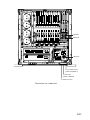
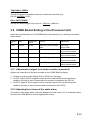
3.6 DIP Switch Setting
J496, J497
C
DCON board (10P6984 or 10P6984A)
A
DC
96
4
J
97
J4
IFES board (10P6983)
IFE
SS
CSAC
D
NAUN
A2DL
CO
N
J1
J1
Processor unit, inside view
3.6.1 CIF2/NMEA2 connector interface selection
The signal format for the CIF2/NMEA2 port (at the back of the processor unit) can be set for
CIF or NMEA by DIP switch S2-8 on the IFES Board (10P6983). The default format is OFF
(CIF).
DIP switch setting
S2-#8: ON
S2-#8: OFF
Format
NMEA
CIF
S2
IFES Board (10P6983)
3-14
3.6.2 Choosing echosounder signal
There are two kinds of echosounder signals, AC signal and DC signal. Set the appropriate
jumper on the CONE board as below according to the input port. The default setting is AC.
See page 3-14 for parts location.
Input port
ES1
ES2/NET
Jumper
J497
J496
Note: The SIGOUT (AC signal) terminal and REC terminal (DC signal) in the output port
are provided for a FURUNO echosounder. Therefore, when using the SIGOUT
terminal, it is not necessary to change the above-mentioned jumper setting.
3-15
(This page intentionally left blank.)
3-16
4. CONNECTING THE EXTERNAL
INTERFACE CS-120A
When upgrading from the CSH-20 series sonar, the External Interface CS-120A can be
used. Connect the CS-120A to the processor unit as shown on the next page. However, we
recommend that you connect external devices directly to the processor unit, to avoid signal
delay.
Install the following power supply kit (option) in the processor unit to enable use of the
CS-120A.
Name: Power Supply Kit
Name
Power supply pcb
Spacer
Protection sheet
Screw
Connector (NJC)
Type: FSV-2403 Code No.: 000-067-013
Type
LEA50F-24-XFND
SQ-22
10-071-3508
M3×8 C2700W
NJC-203-PM
Code No.
000-143-913
000-159-305-10
100-290-712
000-163-190-10
000-160-184-10
Qty
1
4
1
4
1
Remarks
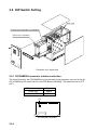
1. Unfasten seven screws to remove the front cover of the processor unit.
Screw
M4x8, 7 pcs.
DC
ON
FUR
UN
O
WA
RN
ING
Details
omitted
Processor unit, front view
4-1
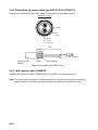
2. Remove two upset screws, detach the plugs J503, J502, J501, J504, J506 and J507,
and then pull out the power module.
Protection sheet
VH4P
Spacer
Power supply
pcb
Detach J503, J502,
J501, J504 and
VH5P J506.
IFE
S
SC
AN
SC
AN
2D
UA
L
DC
ON
Power Module
Upset screws
M5x25 SUS 2 pcs.
Pin
Hole
Detach J507.
Processor unit, front view
3. Fix the power supply pcb (supplied) to the power module with spacers (supplied).
4. Connect two VH connectors (provided on the power module) to the power supply pcb.
5. Set the protection sheet (supplied) to the power supply pcb and fasten it with four
screws.
6. Reattach the power module.
7. Connect between the processor unit and CS-120A as follows.
POWER FOR CS-120A port
NJC-203-PM
Processor Unit
+24V_H
+24V_C
GND
1
2
3
YEL BRN
ORG BRN
PPL BRN
CS-120A
J201
L
E
PP
24V
0V
GND
NN
MM
JJ
KK
BB
EE
DD
Z
TD-H
TD-C
RD-H
RD-C
GND
DSR-C
DSR-H
DTR-H
CIF1 or NMEA2/CIF2
port
CIF_TXD_H
CIF_TXD_C
CIF_RXD_H
CIF_RXD_C
SHIELD
1
2
3
4
10
37-core cable
10S1258
Wiring between processor unit and CS-120A
Note: An echosounder should be connected to the processor unit directly.
4-2
8. Set the DIP switch on the DCON Board as follows.
Input port
CIF1
NMEA 2/CIF 2
DIP switch setting on DCON Board
S3-#2: ON
S3-#3: ON
S3
DCON Board (10P6984 or 10P6984A)
Note: If the CIF1 format is selected, change baud rate to 2400 bps. See CIF BAUD RATE
on page 3-9 for details.
4-3
(This page intentionally left blank.)
4-4
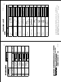
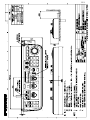
N A M E
DOCUMENT
INSTALLATION MATERIALS
ACCESSORIES
SPARE PARTS
UNIT
O U T L I N E
000-148-571 **
OMJ-13230-*
000-148-573 **
IMJ-13230-*
000-148-731
OME-13231-*
000-149-243
C12-00302-*
006-921-240
CP10-04502
006-921-290
CP10-04506
007-008-780
FP10-02901
006-921-340
SP10-02601
000-067-043 **
FSV-3002-60
DESCRIPTION/CODE №
(略図の寸法は、参考値です。
2.(*1)䈱ขᛒ⺑ᦠ(⧷)䈲䍂FSV-30Sኾ↪䈪䈜䇯
*1 FOR FSV-30S.
10CT-X-9851
DIMENSIONS IN DRAWING FOR REFERENCE ONLY.)
1.䍘-䍢䍼⇟ภᧃየ䈱[**]䈲䇮ㆬᛯຠ䈱ઍဳᑼ/䍘䍎䍢䉕䈚䉁䈜䇯
CODE NUMBER ENDED BY "**" INDICATES THE NUMBER OF TYPICAL MATERIAL.
OPERATOR'S MANUAL
取扱説明書(和)
INSTALLATION MANUAL
装備要領書(和)
OPERATOR'S MANUAL
取扱説明書(英)
INPUT JOLTAGE SETTING
電源設定書
図書
INSTALLATION MATERIALS
工事材料
INSTALLATION MATERIALS
工事材料
工事材料
ACCESSORIES
付属品
付属品
SPARE PARTS
予備品
予備品
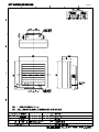
PROCESSOR UNIT
制御部
ユニット
10CT-X-9851 -2
FSV-3002-60-J/E,FSV-3002-70-J/E,FSV-3002S-60-E/70-E
PACKING LIST
1
1
(*1)
1
1
1
1
1
1
1
Q'TY
A-1
1/1
%100'%614
0%5
㩄㩒㩂㩊
0%5
*':$1.6
5.166'&9#5*'4*'#&
ⷺ㩇㩢㩦㩢㩈㩛㩇$
%106#%62+0
㩄㩧㩊㩂㩎㩕㩩㩧㧔
%100'%614
㩄㩒㩂㩊
㧕
ฬޓޓ⒓
0#/'
⇛ޓޓ࿑
176.+0'
%1&'01 0%52
%1&'01 0%5241*5
/:575
%1&'01 /:575
(
%1&'01
*8(
ဳฬ㧛ⷙᩰ
&'5%4+26+105
ᢙ㊂
36;
%2
6;2'
ᓮㇱ↪
(14241%'551470+6
ᓮㇱ↪
(14241%'551470+6
ᓮㇱ↪
(14241%'551470+6
ᓮㇱ↪
(14241%'551470+6
↪ㅜ㧛⠨
4'/#4-5
%1: 㧲㨁㧾㨁㧺㧻ޓ㧱㧸㧱㧯㨀㧾㧵㧯ޓ㧯㧻ޓ㧚㧘㧸㨀㧰
㧔⇛࿑ߩኸᴺߪޔෳ⠨୯ߢߔ&ޓޕ+/'05+105+0&4#9+0)(144'('4'0%'10.;㧕
%1:
6916;2'5#0&%1&'5/#;$'.+56'&(14#0+6'/6*'.19'4241&7%6/#;$'5*+22'&+02.#%'1(6*'722'4241&7%6
37#.+6;+56*'5#/'
ဳᑼ㩄㨺㩎㩨⇟ภ߇㧞Ბߩ႐วޔਅᲑࠃࠅᲑߦઍࠊࠆㆊᷰᦼຠߢࠅޔ߅ߥޓޕߔ߹ߡߞ߇߆ࠄߜߤޔຠ⾰ߪᄌࠊࠅ߹ߖࠎޕ
⇟ภ
01
+056#..#6+10/#6'4+#.5
Ꮏ᧚ᢱ
%1&'01
A-2
%100'%614
54%0
㩄㩒㩂㩊
54%0㧕
%100'%614
54%0
㩄㩒㩂㩊
54%0㧕
ฬޓޓ⒓
0#/'
⇛ޓޓ࿑
176.+0'
%1&'
01
54%0#2
%1&'
01
54%0#2
ဳฬ㧛ⷙᩰ
&'5%4+26+105
ᢙ㊂
36;
%2
6;2'
↪ㅜ㧛⠨
4'/#4-5
%1: 㧲㨁㧾㨁㧺㧻ޓ㧱㧸㧱㧯㨀㧾㧵㧯ޓ㧯㧻ޓ㧚㧘㧸㨀㧰
㧔⇛࿑ߩኸᴺߪޔෳ⠨୯ߢߔ&ޓޕ+/'05+105+0&4#9+0)(144'('4'0%'10.;㧕
%1:
ဳᑼ㩄㨺㩎㩨⇟ภ߇㧞Ბߩ႐วޔਅᲑࠃࠅᲑߦઍࠊࠆㆊᷰᦼຠߢࠅޔ߅ߥޓޕߔ߹ߡߞ߇߆ࠄߜߤޔຠ⾰ߪᄌࠊࠅ߹ߖ
ࠎޕ
6916;2'5#0&%1&'5/#;$'.+56'&(14#0+6'/6*'.19'4241&7%6/#;$'5*+22'&+02.#%'1(6*'722'4
241&7%637#.+6;+56*'5#/'
⇟ภ
01
+056#..#6+10/#6'4+#.5
Ꮏ᧚ᢱ
%1&'01
A-3
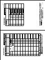
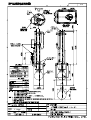
N A M E
O U T L I N E
007-008-540
CP10-06201
007-008-530
SP10-03101
000-067-047
FSV-301
DESCRIPTION/CODE №
10CT-X-9852 -0
10CT-X-9852
DIMENSIONS IN DRAWING FOR REFERENCE ONLY.)
INSTALLATION MATERIALS
SPARE PARTS
UNIT
(略図の寸法は、参考値です。
INSTALLATION MATERIALS
工事材料
工事材料
SPARE PARTS
予備品
予備品
TRANSCEIVER UNIT
送受信装置
ユニット
FSV-301
PACKING LIST
1
1
1
Q'TY
A-4
1/1
%122'4564#2
㨻㨺㩇᧼
%4+/210.7)
⌕┵ሶ
%106#%62+0
㩄㩧㩊㩂㩎㩕㩩㩧
%100'%614
㩄㩒㩂㩊
㧕
ฬޓޓ⒓
0#/'
⇛ޓޓ࿑
176.+0'
%1&'
01
9'#
%1&'
01
9'#41*5
(8㨻㨿
(8
%1&'
01
(
%1&'
01
*8(
ဳฬ㧛ⷙᩰ
&'5%4+26+105
%2
6;2'
ᢙ㊂
36;
ㅍฃାⵝ⟎↪
(1464#05%'+8'4
70+6
ㅍฃାⵝ⟎↪
(1464#05%'+8'4
70+6
ㅍฃାⵝ⟎↪
(1464#05%'+8'4
70+6
ㅍฃାⵝ⟎↪
(1464#05%'+8'4
70+6
↪ㅜ㧛⠨
4'/#4-5
%6: 㧲㨁㧾㨁㧺㧻ޓ㧱㧸㧱㧯㨀㧾㧵㧯ޓ㧯㧻ޓ㧚㧘㧸㨀㧰
㧔⇛࿑ߩኸᴺߪޔෳ⠨୯ߢߔ&ޓޕ+/'05+105+0&4#9+0)(144'('4'0%'10.;㧕
%6:
ဳᑼ㩄㨺㩎㩨⇟ภ߇㧞Ბߩ႐วޔਅᲑࠃࠅᲑߦઍࠊࠆㆊᷰᦼຠߢࠅޔ߅ߥޓޕߔ߹ߡߞ߇߆ࠄߜߤޔຠ⾰ߪᄌࠊࠅ߹ߖ
ࠎޕ
6916;2'5#0&%1&'5/#;$'.+56'&(14#0+6'/6*'.19'4241&7%6/#;$'5*+22'&+02.#%'1(6*'722'4
241&7%637#.+6;+56*'5#/'
⇟ภ
01
+056#..#6+10/#6'4+#.5
Ꮏ᧚ᢱ
%1&'01
A-5
0#/'
176.+0'
.1%#.#55'/$.+0)ޓ2#465
52#4'2#465
70+6
(8
.(
/575
/575
/575
/:575
9'#41*5
%1#
8
%
52
(58
&'5%4+26+10%1&'ͳ
%6: 36;
䋨⇛࿑䈱ኸᴺ䈲䇮ෳ⠨୯䈪䈜䇯㩷㩷㪛㪠㪤㪜㪥㪪㪠㪦㪥㪪㩷㪠㪥㩷㪛㪩㪘㪮㪠㪥㪞㩷㪝㪦㪩㩷㪩㪜㪝㪜㪩㪜㪥㪚㪜㩷㪦㪥㪣㪰㪅䋩
%6:
A-6
㪫㪮㪦㩷㪫㪰㪧㪜㪪㩷㪘㪥㪛㩷㪚㪦㪛㪜㪪㩷㪤㪘㪰㩷㪙㪜㩷㪣㪠㪪㪫㪜㪛㩷㪝㪦㪩㩷㪘㪥㩷㪠㪫㪜㪤㪅㩷㩷㪫㪟㪜㩷㪣㪦㪮㪜㪩㩷㪧㪩㪦㪛㪬㪚㪫㩷㪤㪘㪰㩷㪙㪜㩷㪪㪟㪠㪧㪧㪜㪛㩷㪠㪥㩷㪧㪣㪘㪚㪜㩷㪦㪝㩷㪫㪟㪜㩷㪬㪧㪧㪜㪩㩷
㪧㪩㪦㪛㪬㪚㪫㪅㩷㪨㪬㪘㪣㪠㪫㪰㩷㪠㪪㩷㪫㪟㪜㩷㪪㪘㪤㪜㪅
ဳᑼ㪆䍘䍎䍢䍼⇟ภ䈏䋲Ბ䈱႐ว䇮ਅᲑ䉋䉍Ბ䈮ઍ䉒䉎ㆊᷰᦼຠ䈪䈅䉍䇮䈬䈤䉌䈎䈏䈦䈩䈇䉁䈜䇯䇭䈭䈍䇮ຠ⾰䈲ᄌ䉒䉍䉁䈞䉖䇯
%4+/210.7)
⌕┵ሶ
524+0)9#5*'4
㩔㩨㩒ᐳ㊄
(.#69#5*'4
㩚㩀㩨㩁ਣᐔᐳ㊄
*':076
ⷺ㩏㨹㩎㩆㨷
*':#)10#.*'#&5%4'9
ⷺ㩘㩨㩣㩎ోޓ㩒㩆㩨
%122'4564#2
㨻㨺㩇᧼
14+0)
1㩢㩧㩂㩨
8
.1%#.#55'/$.+0)
⚵ㇱຠ⺑
⚵ㇱຠ
52#4'2#465
੍ຠ
੍ຠ
*7..70+6
ਅⵝ⟎
࡙࠾࠶࠻
(58
㧼㧭㧯㧷㧵㧺㧳ޓ㧸㧵㧿㨀
0#/'
176.+0'
0#/'
#%%'5514+'5
70+6
176.+0'
36;
%6:
%1:
䋨⇛࿑䈱ኸᴺ䈲䇮ෳ⠨୯䈪䈜䇯㩷㩷㪛㪠㪤㪜㪥㪪㪠㪦㪥㪪㩷㪠㪥㩷㪛㪩㪘㪮㪠㪥㪞㩷㪝㪦㪩㩷㪩㪜㪝㪜㪩㪜㪥㪚㪜㩷㪦㪥㪣㪰㪅䋩
(2
(58
&'5%4+26+10%1&'ͳ
A-8
䋨⇛࿑䈱ኸᴺ䈲䇮ෳ⠨୯䈪䈜䇯㩷㩷㪛㪠㪤㪜㪥㪪㪠㪦㪥㪪㩷㪠㪥㩷㪛㪩㪘㪮㪠㪥㪞㩷㪝㪦㪩㩷㪩㪜㪝㪜㪩㪜㪥㪚㪜㩷㪦㪥㪣㪰㪅䋩
㪉㪅㩿㪁㪈㪀ශ䈱䍗㪄䍪䍼䍷⚵ຠ䈲䇮㪌㫄㪃㪈㪇㫄䈱㐳䈘䈏䈅䉍䉁䈜䇯
㪌㫄㪃㪈㪇㫄㩷㪚㪘㪙㪣㪜㩷㪠㪪㩷㪪㪜㪣㪜㪚㪫㪠㪭㪜㩷㪦㪥㩷㪛㪜㪤㪘㪥㪛㪅
㪈㪅䍘䍎䍢䍼ᧃየ䈮㪲㪁㪁㪴䈱ઃ䈇䈢䍳䍤䍍䍢䈲ઍ䈱ဳᑼ㪆䍘䍎䍢䍼䉕␜䈚䈩䈇䉁䈜䇯
㪛㪦㪬㪙㪣㪜㩷㪘㪪㪫㪜㪩㪠㪪㪢㩷㪛㪜㪥㪦㪫㪜㪪㩷㪚㪦㪤㪤㪦㪥㪣㪰㩷㪬㪪㪜㪛㩷㪜㪨㪬㪠㪧㪤㪜㪥㪫㪅
#%%'5514+'5
ઃዻຠ
ઃዻຠ
%10641.70+6
ᠲㇱ
࡙࠾࠶࠻
%1: 㪫㪮㪦㩷㪫㪰㪧㪜㪪㩷㪘㪥㪛㩷㪚㪦㪛㪜㪪㩷㪤㪘㪰㩷㪙㪜㩷㪣㪠㪪㪫㪜㪛㩷㪝㪦㪩㩷㪘㪥㩷㪠㪫㪜㪤㪅㩷㩷㪫㪟㪜㩷㪣㪦㪮㪜㪩㩷㪧㪩㪦㪛㪬㪚㪫㩷㪤㪘㪰㩷㪙㪜㩷㪪㪟㪠㪧㪧㪜㪛㩷㪠㪥㩷㪧㪣㪘㪚㪜㩷㪦㪝㩷㪫㪟㪜㩷㪬㪧㪧㪜㪩㩷
㪧㪩㪦㪛㪬㪚㪫㪅㩷㪨㪬㪘㪣㪠㪫㪰㩷㪠㪪㩷㪫㪟㪜㩷㪪㪘㪤㪜㪅
36;
(58(58(58
㧼㧭㧯㧷㧵㧺㧳ޓ㧸㧵㧿㨀
ဳᑼ㪆䍘䍎䍢䍼⇟ภ䈏䋲Ბ䈱႐ว䇮ਅᲑ䉋䉍Ბ䈮ઍ䉒䉎ㆊᷰᦼຠ䈪䈅䉍䇮䈬䈤䉌䈎䈏䈦䈩䈇䉁䈜䇯䇭䈭䈍䇮ຠ⾰䈲ᄌ䉒䉍䉁䈞䉖䇯
(8
.(
/575
/575
/575
/:575
9'#41*5
%1#
8
%
52
(58
&'5%4+26+10%1&'ͳ
A-7
㪫㪮㪦㩷㪫㪰㪧㪜㪪㩷㪘㪥㪛㩷㪚㪦㪛㪜㪪㩷㪤㪘㪰㩷㪙㪜㩷㪣㪠㪪㪫㪜㪛㩷㪝㪦㪩㩷㪘㪥㩷㪠㪫㪜㪤㪅㩷㩷㪫㪟㪜㩷㪣㪦㪮㪜㪩㩷㪧㪩㪦㪛㪬㪚㪫㩷㪤㪘㪰㩷㪙㪜㩷㪪㪟㪠㪧㪧㪜㪛㩷㪠㪥㩷㪧㪣㪘㪚㪜㩷㪦㪝㩷㪫㪟㪜㩷㪬㪧㪧㪜㪩㩷
㪧㪩㪦㪛㪬㪚㪫㪅㩷㪨㪬㪘㪣㪠㪫㪰㩷㪠㪪㩷㪫㪟㪜㩷㪪㪘㪤㪜㪅
.1%#.#55'/$.+0)ޓ2#465
52#4'2#465
70+6
%6: ဳᑼ㪆䍘䍎䍢䍼⇟ภ䈏䋲Ბ䈱႐ว䇮ਅᲑ䉋䉍Ბ䈮ઍ䉒䉎ㆊᷰᦼຠ䈪䈅䉍䇮䈬䈤䉌䈎䈏䈦䈩䈇䉁䈜䇯䇭䈭䈍䇮ຠ⾰䈲ᄌ䉒䉍䉁䈞䉖䇯
%4+/210.7)
⌕┵ሶ
524+0)9#5*'4
㩔㩨㩒ᐳ㊄
(.#69#5*'4
㩚㩀㩨㩁ਣᐔᐳ㊄
*':076
ⷺ㩏㨹㩎㩆㨷
*':#)10#.*'#&5%4'9
ⷺ㩘㩨㩣㩎ోޓ㩒㩆㩨
%122'4564#2
㨻㨺㩇᧼
14+0)
1㩢㩧㩂㩨
8
.1%#.#55'/$.+0)
⚵ㇱຠ⺑
⚵ㇱຠ
52#4'2#465
੍ຠ
੍ຠ
*7..70+6
ਅⵝ⟎
࡙࠾࠶࠻
(58
㧼㧭㧯㧷㧵㧺㧳ޓ㧸㧵㧿㨀
47$$'4(''6
㩄㩨㩛⿷
*':$1.6
9#5*'4*'#&
㨻㩖㩩㩈㨹㩎7+㩈㩛㩇$
18#.*'#&5%4'9
㩅㩡ዊ㩒㩆㩨
524+0)9#5*'4
ࡃࡀᐳ㊄
*':076
ⷺ㩏㨹㩎㩆㨷
(.#69#5*'4
㩚㩀㩨㩁ᐔᐳ㊄
&7//;(+./
㩄㩒㩂㩊㩆㨺㩣
&756%18'4-$
㩊㩨㩇㩎㩀㩔㩨㨺-$
-$(+:0)2.#6'
-$⋥ઃߌ㊄ౕ
ฬޓޓ⒓
0#/'
⇛ޓޓ࿑
176.+0'
%1&'01
5,㩂㩥
%1&'01
/:575
%1&'01
/:%9/$0+
%1&'01
/%9
%1&'01
/%$
%1&'01
/%4
%1&'01
41*5
%1&'01 41*5
%1&'01
41*5
ဳฬ㧛ⷙᩰ
&'5%4+26+105
(2
6;2'
ᢙ㊂
36;
ᠲㇱ↪
(14%10641..70+6
ᠲㇱ↪
(14%10641..70+6
ᠲㇱ↪
(14%10641..70+6
ᠲㇱ↪
(14%10641..70+6
ᠲㇱ↪
(14%10641..70+6
ᠲㇱ↪
(14%10641..70+6
ᠲㇱ↪
(14%10641..70+6
ᠲㇱ↪
(14%10641..70+6
ᠲㇱ↪
(14%10641..70+6
↪ㅜ㧛⠨
4'/#4-5
%1: 㧲㨁㧾㨁㧺㧻ޓ㧱㧸㧱㧯㨀㧾㧵㧯ޓ㧯㧻ޓ㧚㧘㧸㨀㧰
㧔⇛࿑ߩኸᴺߪޔෳ⠨୯ߢߔ&ޓޕ+/'05+105+0&4#9+0)(144'('4'0%'10.;㧕
%1:
6916;2'5#0&%1&'5/#;$'.+56'&(14#0+6'/6*'.19'4241&7%6/#;$'5*+22'&+02.#%'1(6*'722'4241&7%6
37#.+6;+56*'5#/'
ဳᑼ㩄㨺㩎㩨⇟ภ߇㧞Ბߩ႐วޔਅᲑࠃࠅᲑߦઍࠊࠆㆊᷰᦼຠߢࠅޔ߅ߥޓޕߔ߹ߡߞ߇߆ࠄߜߤޔຠ⾰ߪᄌࠊࠅ߹ߖࠎޕ
⇟ภ
01
#%%'5514+'5
ઃዻຠ
%1&'01
A-9
1
番 号
NO.
MEMORY CARD
メモリカード組品
略 図
OUTLINE
CODE NO.
007-008-790
FP10-02902
型名/規格
DESCRIPTIONS
FP10-02901
TYPE
1
数量
Q'TY
1/1
10CT-X-9501
制御部用
FOR PROCESSOR UNIT
用途/備考
REMARKS
10CT-X-9501 -0
FURUNO ELECTRIC CO .,LTD.
(略図の寸法は、参考値です。 DIMENSIONS IN DRAWING FOR REFERENCE ONLY.)
名 称
NAME
ACCESSORIES
付属品表
007-008-780
CODE NO.
A-10
).#5567$'
(75'
㩕㨷㨺㩇㩨
).#5567$'
(75'
㩕㨷㨺㩇㩨
).#5567$'
(75'
㩕㨷㨺㩇㩨
).#5567$'
(75'
㩕㨷㨺㩇㩨
()/$8#
2$(
()$18#
()$18
#2$(
()$18
#2$(
2'4
8'5
ㅍฃାⵝ⟎↪
(1464#05%'+8'470+6
ㅍฃାⵝ⟎↪
(1464#05%'+8'470+6
ㅍฃାⵝ⟎↪
(1464#05%'+8'470+6
ㅍฃାⵝ⟎↪
(1464#05%'+8'470+6
()$1#
#%8
()$8
#2$(
2'4
8'5
&9)01
2'4
5'6
ᜰ␜ⵝ⟎㧪ᓮㇱ↪
(14&+52.#;70+6
5'652'4
8'55'.
$1:012
4'/#4-5%1&'01
%1:
37#06+6;
914-+0)
52#4'
52
75'
ဳᑼ㩄㨺㩎㩨⇟ภ߇㧞Ბߩ႐วޔਅᲑࠃࠅᲑߦઍࠊࠆㆊᷰᦼຠߢࠅޔ߅ߥޓޕߔ߹ߡߞ߇߆ࠄߜߤޔຠ⾰ߪ
ᄌࠊࠅ߹ߖࠎޕ
6916;2'5#0&%1&'5/#;$'.+56'&(14#0+6'/6*'.19'4241&7%6/#;$'5*+22'&+02.#%'1(6*'
722'4241&7%637#.+6;+56*'5#/'
(74701'.'%64+%%1.6&
176.+0'
&9)01
14
6;2'01
6;2'
A-12
%1: 㧔⇛࿑ߩኸᴺߪޔෳ⠨୯ߢߔ&ޓޕ+/'05+105+0&4#9+0)(ޓ144'('4'0%'10.;㧕
/(450#/'
(75'
㩕㨷㨺㩇㩨
0#/'1(
2#46
52#4'2#465.+56(14
ဳᑼ㩄㨺㩎㩨⇟ภ߇㧞Ბߩ႐วޔਅᲑࠃࠅᲑߦઍࠊࠆㆊᷰᦼຠߢࠅޔ߅ߥޓޕߔ߹ߡߞ߇߆ࠄߜߤޔຠ
⾰ߪᄌࠊࠅ߹ߖࠎޕ
6916;2'5#0&%1&'5/#;$'.+56'&(14#0+6'/6*'.19'4241&7%6/#;$'5*+22'&+02.#%'1(
6*'722'4241&7%637#.+6;+56*'5#/'
+6'/
01
5*+201
%1&'01
㧔⇛࿑ߩኸᴺߪޔෳ⠨୯ߢߔ&ޓޕ+/'05+105+0&4#9+0)(ޓ144'('4'0%'10.;㧕
&9)01
2'4
5'6
5'652'4
8'55'.
$1:012
%6: A-11
4'/#4-5%1&'01
%6:
37#06+6;
914-+0)
52#4'
52
75'
6;2'
&9)01
14
6;2'01
(74701'.'%64+%%1.6&
176.+0'
52#4'2#465.+56(14
0#/'1(
2#46
/(450#/'
+6'/
01
5*+201
%1&'01
(75'
㩕㨷㨺㩇㩨
()/$#8
()/$8#
2$(
&9)01
14
6;2'01
2'4
8'5
&9)01
2'4
5'6
914-+0)
52#4'
(14*#..70+6
ਅⵝ⟎
ᓮེ↪
4'/#4-5%1&'01
%1:
37#06+6;
75'
ဳᑼ㩄㨺㩎㩨⇟ภ߇㧞Ბߩ႐วޔਅᲑࠃࠅᲑߦઍࠊࠆㆊᷰᦼຠߢࠅޔ߅ߥޓޕߔ߹ߡߞ߇߆ࠄߜߤޔຠ⾰ߪᄌ
ࠊࠅ߹ߖࠎޕ
6916;2'5#0&%1&'5/#;$'.+56'&(14#0+6'/6*'.19'4241&7%6/#;$'5*+22'&+02.#%'1(6*'
722'4241&7%637#.+6;+56*'5#/'
㧔⇛࿑ߩኸᴺߪޔෳ⠨୯ߢߔ&ޓޕ+/'05+105+0&4#9+0)(ޓ144'('4'0%'10.;㧕
(74701'.'%64+%%1.6&
176.+0'
52#4'2#465.+56(14
0#/'1(
2#46
/(450#/'
+6'/
01
5*+201
5'652'4
8'55'.
$1:012
52
6;2'
A-13
%1: %1&'01
%100'%614
54%0
㩄㩒㩂㩊
54%0
%100'%614
54%0
㩄㩒㩂㩊
54%0
%100'%614
54%0
㩄㩒㩂㩊
54%0㧕
%100'%614
54%0
㩄㩒㩂㩊
54%0㧕
%100'%614
54%0
㩄㩒㩂㩊
54%0㧕
ฬޓޓ⒓
0#/'
⇛ޓޓ࿑
176.+0'
%1&'01
54%0#5
%1&'01
54%0#2
%1&'01
54%0#2
%1&'01
54%0#2
%1&'01
54%0#2
ဳฬ㧛ⷙᩰ
&'5%4+26+105
%2
6;2'
ᢙ㊂
36;
↪ㅜ㧛⠨
4'/#4-5
%1: 㧲㨁㧾㨁㧺㧻ޓ㧱㧸㧱㧯㨀㧾㧵㧯ޓ㧯㧻ޓ㧚㧘㧸㨀㧰
㧔⇛࿑ߩኸᴺߪޔෳ⠨୯ߢߔ&ޓޕ+/'05+105+0&4#9+0)(144'('4'0%'10.;㧕
%1:
6916;2'5#0&%1&'5/#;$'.+56'&(14#0+6'/6*'.19'4241&7%6/#;$'5*+22'&+02.#%'1(6*'722'4241&7%6
37#.+6;+56*'5#/'
ဳᑼ㩄㨺㩎㩨⇟ภ߇㧞Ბߩ႐วޔਅᲑࠃࠅᲑߦઍࠊࠆㆊᷰᦼຠߢࠅޔ߅ߥޓޕߔ߹ߡߞ߇߆ࠄߜߤޔຠ⾰ߪᄌࠊࠅ߹ߖࠎޕ
⇟ภ
01
+056#..#6+10/#6'4+#.5
Ꮏ᧚ᢱ
%1&'01
A-14
D-1
D-2
D-3
D-4
Y. Hatai
D-5
Y. Hatai
D-6
Takahashi T.
Y. Hatai
D-7
Takahashi T.
Y. Hatai
D-8
Y. Hatai
D-9
D-10
This page is intentionally left blank.
1
*1
220VAC TPYCY-4
3φ,50/60Hz
A
2
TB-C101
1 U
2 V
3 W
4
5
6
7
8
CN-C101
J1
A
TT
FSV-2431
上下装置
HULL UNIT
FSV-303/304
B
10S2145,23m(*2)
10S2144,13m(*2)
10S2078,8m,φ17
ミドリ
アカ
アオ
クロ
ムラサキ
シロ
チャ
クロ
チャ
シロ
*1
アオ
IV-8sq.
シロ
キ
クロ
シロ
クロ
ムラサキ
クロ
アカ
シロ
ミドリ
クロ
アカ
クロ
ミドリ
シロ
キ
シロ
*3
GRN
RED
BLU
BLK
PPL
WHT
BRN
BLK
BRN
WHT
BLU
WHT
YEL
BLK
WHT
BLK
PPL
BLK
RED
WHT
GRN
BLK
RED
BLK
GRN
WHT
YEL
WHT
P
P
P
P
P
P
P
P
P
P
P
P
P
P
10S2240, *3
5/15m,φ16
接続箱
JUNCTION BOX
FSV-305 *2
J1-20 J1-20
B201 B101
B220 B120
C
100/110/115/
220/230 VAC
1φ,50/60Hz
4
制御部 FSV-3002/3002S
*4
PROCESSOR UNIT
送受信装置 FSV-301
TRANSCEIVER UNIT
*3
10S2223,φ16
送受波器
TRANSDUCER
3
アース銅板 *1
COPPER STRAP
延長キット *2
EXTENSION KIT
*1
DPYCYS-2.5
CN-B102 CN-B101 J2
A
MSRXD-H
B
MSRXD-C
C
MSTXD-H
D
MSTXD-C
E
UPLSW-H
F
UPLSW-C
H
DEMGUP-H
LL
DEMGUP-C
J
MDLSW-H
K
MDLSW-C
L
DNLSW-H
M
DNLSW-C
N
DNCMD-H
P
DNCMD-C
R
UPCMD-H
S
UPCMD-C
T
DUPLSW-H
U
DUPLSW-C
V
TSFLG-H
X
TSFLG-C
W
MSROLL
Y
MSR_GND
Z
MSPITCH
AA
MSP_GND
BB
PWRHUL-H
CC
PWRHUL-C
DD
PWRHUL-H
EE
PWRHUL-C
FF
HH
TRX 10P6960 x10
JJ
B201
P1~P2
KK
MM
B202
P1~P2
NN
PP
B203
P1~P2
RR
SS
B204
P1~P2
TT
B205
P1~P2
B206
P1~P2
B207
P1~P2
B208
P1~P2
B209
P1~P2
B210
P1~P2
J1
A
B
C
D
E
F
H
LL
J
K
N
P
R
S
T
U
V
X
W
Y
Z
AA
BB
CC
JJ
NN
PP
TT
J445 CN-A101
A TRXRXD-H
B TRXRXD-C
C TRXTXD-H
D TRXTXD-C
E SIG_D0-H
F SIG_D0-C
H DEMGUP-H
LL DEMGUP-C
J SIG_D1-H
K SIG_D1-C
L SIG_D2-H
M SIG_D2-C
N SIG_D3-H
P SIG_D3-C
R SIG_D4-H
S SIG_D4-C
T SIG_D5-H
U SIG_D5-C
V DUPLSW-H
X DUPLSW-C
W AUDIO-H
Y AUDIO-C
Z +12V
AA GND
BB EXTKP-C
CC EXTKP-H
DD SIG_D6-H
EE SIG_D6-C
FF SIG_D7-H
HH SIG_D7-C
JJ KP-H
KK KP-C
MM FS-H
NN FS-C
PP ENB-H
RR EMB-C
SS FSCLK-H
TT FECLK-C
10S1258,φ18,MAX.100m
アカ 11 RED
P
チャ 11 BRN
クロ 10 BLK
P
シロ 10 WHT
ダイ 12 ORG
P
チャ 12 BRN
アカ 19 RED
P
ダイ 19 ORG
クロ 9 BLK
P
ハイ 9 GRY
キ
13 YEL
P
チャ 13 BRN
クロ 8 BLK
P
ムラサキ 8 PPL
ダイ 4 ORG
P
クロ 4 BLK
クロ 3 BLK
P
アカ 3 RED
キ
5 YEL
P
クロ 5 BLK
チャ 2 BRN
P
クロ 2 BLK
ミドリ 6 GRN
P
クロ 6 BLK
シールド SHIELD
シンセン
CORE
ミドリ 14 GRN
P
チャ 14 BRN
クロ 7 BLK
P
アオ 7 BLU
アオ 15 BLU
P
チャ 15 BRN
チャ 18 BRN
P
シロ 18 WHT
ムラサキ 16 PPL
P
チャ 16 BRN
チャ 17 BRN
P
ハイ 17 GRY
CN-A103(108)
J411(421)
CN1RXD-H A
CN1RXD-C B
CN1TXD-H C
CN1TXD-C D
CN1TXA-H E
CN1TXA-C F
CN1TXB-H J
CN1TXB-C K
CN1TYA-H L
CN1TYA-C M
CN1TYB-H N
CN1TYB-C P
GND JJ
GND KK
GND LL
CN1PON-H
CN1PON-C
CN1POF-H
CN1POF-C
CN1AUDV1
CN1AUDV2
CV1AUDV3
CN1BRLV1
CN1BRLV2
CN1BRLV3
+12V
GND
+12V
GND
NC
NC
R
S
T
U
V
X
Z
W
Y
CC
PP
MM
RR
NN
SS
TT
5
*3 *5
10S2076,10m(5m)
キ
4 YEL
P
クロ 4 BLK
ミドリ 3 GRN
P
クロ 3 BLK
アオ 5 BLU
P
クロ 5 BLK
チャ 6 BRN
P
クロ 6 BLK
ムラサキ 7 PPL
P
クロ 7 BLK
アカ 8 RED
P
シロ 8 WHT
ミドリ 14 GRN
P
アカ 14 RED
P
P
P
P
P
P
P
*4
CN-A104(109)
J412(422) KEC-15P
DS1V-R 1
GND 6
DS1V-G 2
GND 7
DS1V-B 3
GND 8
DS1VSY 14
GND 5
DS1HSY 13
GND 10
シロ
クロ
アカ
クロ
シロ
ミドリ
キ
シロ
シロ
アオ
ムラサキ
シロ
チャ
シロ
1
1
2
2
9
9
10
10
11
11
13
13
12
12
WHT
BLK
RED
BLK
WHT
GRN
YEL
WHT
WHT
BLU
PPL
WHT
BRN
WHT
6
S-1
操作部 FSV-3001
CONTROL UNIT
XH-15P
3
4
1
2
5
6
7
8
9
10
11
12
13
14
15
XH-14P
1
2
3
4
5
6
7
8
9
10
11
13
12
14
*1
MONITOR CABLE
J1 CN-A201
CN1RXD-H
CN1RXD-C
CN1TXD-H
CN1TXD-C
CN1TXA-H
CN1TXA-C
CN1TXB-H
CN1TXB-C
CN1TYA-H
CN1TYA-C
CN1TYB-H
CN1TYB-C
GND
GND
GND
J2 CN-A202
CN1PON-H
CN1PON-C
CN1POF-H
CN1POF-C
CN1AUDV1
CN1AUDV2
CN1AUDV3
CN1BRLV1
CN1BRLV2
CN1BRLV3
+12V
GND
+12V
GND
外部モニター
EXT. MONITOR *1
POWER
TB-B101
1 AC_IN-H
2 AC_IN-C
アース銅板
COPPER STRAP
WEA-1004
W=50,1.2m
D
*1
DPYCY-1.5
NCS-253-P
3
2
1
CN-A110
J16
AC_IN-H
AC_IN-C
SHIELD
*1
IV-8sq.
注記
*1)造船所手配
*2)オプション。
*3)コネクタは工場にて取付済み。
*4)( ):副表示部/副操作部用。
*5)和文仕様では5/10mより選択。
DRAWN
NOTE
*1: SHIPYARD SUPPLY.
*2: OPTION.
*3: CONNECTOR PLUGS FITTED AT FACTORY.
*4: ( ): FOR SUB-MONITOR OR SUB-CONTROL.
*5: 5m CABLE AVAILABLE FOR JAPANESE ONLY.
9/Jul/08
CHECKED
9/Jul/08
APPROVED
TITLE
T.YAMASAKI
名称
T.TAKENO
相互結線図
18/Jul/08 R.Esumi
SCALE
MASS
NAME
kg
DWG No.
C1323-C02- D
FSV-30/30S
カラースキャニングソナー
10-080-0101-0
COLOR SCANNING SONAR
INTERCONNECTION DIAGRAM
FURUNO ELECTRIC CO., LTD.
1
2
PCS-E68PM
データ収録装置
DATA RECORDER
メンテナンス専用
FOR MAINTENANCE
魚探 I/F
ES I/F
VI-1100A
J14 PC IF
1
*4
A
*2
SRCN6A16-10P
02S8040,6m
68
1
2
3
4
5
6
7
8
9
10
*4
*2
*2 SRCN6A21-10S
外部KP CO-0.2x5P
1
EXTERNAL KP
2
3
4
5
6
7
8
9
10
*4
B
外部スピーカ
EXTERNAL SPEAKER
SEM-21Q
1
2
3
4
5
6
7
8
2.8m
1
2
NJC-203PM
CS-120A
1
2
3
C
SRCN2A21-16S
注記
*1)造船所手配
*2)オプション。
*3)コネクタは工場にて取付済み。
*4)コネクタクランプでアースに落とす。
*5)IFES基板S2 #8にて選択。
工場出荷時はCIF(OFF)。
D
NOTE
*1: SHIPYARD SUPPLY.
*2: OPTION.
*3: CONNECTOR PLAG FITTED AT FACTORY.
*4: GROUND THRU CONNECTOR CLAMP.
*5: SELECT CIF OR NMEA AT S2 #8 ON
IFES BOARD. DEFAULT IS CIF (OFF).
DRAWN
Dec. 26 '06
CHECKED
APPROVED
SCALE
DWG.No.
1
2
3
4
5
6
7
8
9
10
11
12
13
14
16
CO-0.2x2P: CO-SPEVV-SB-C 0.2x2P,φ10.5
CO-0.2x5P: CO-SPEVV-SB-C 0.2x5P,φ13.5
TITLE
名称
TAKAHASHI. T
kg
C1318-C03- N
FSV-2402/2402S/3002/3002S/8402
制御部外部信号接続
相互結線図
FSV-24/24S/30/30S/84/84L
MASS
S-2
MONITOR J1
KEC-15P
外部モニター
MD-R 1
EXTERNAL MONITOR
制御部
GND 6
2
MD-G
PROCESSOR UNIT
GND 7
FSV-2402/2402S
MD-B 3
FSV-3002/3002S
GND 8
FSV-8402
MD-V-SYNC 14
GND 5
J12 ES2/NET
MD-H-SYNC 13
ES2-SIG-IN
GND 10
GND
*4
KP-DN-IN
*3
*2
NC
NMEA1 J3
MJ-A6SPF
MJ-A6SPF0011/0012 航法装置
NMEA1-TXD-H 1
ES2-WL-IN
5/10m,φ6
NAVIGATOR
NMEA1-TXD-C 2
GND
GND
NMEA1-RXD-H 3
KP-UP-IN
NMEA1-RXD-C 4
*4
NC
SHIELD 6
GND
*3
*2
NMEA2/CIF2 J4
MJ-A6SPF
MJ-A6SPF0011/0012 航法装置
*5
NMEA2-TXD-H 1
J13 EXT-KP
5/10m,φ6
NAVIGATOR
INTKP1
NMEA2-TXD-C 2
NMEA2-RXD-H 3
GND
NMEA2-RXD-C 4
INTKP2
SHIELD 6
GND
*4
INTKP3
*2
SRCN6A13-5P
GND
CIF1 J5
CO-0.2x2P
GND
CIF-TXD-H 1
潮流計
P
EXT-KP-IN-H
CIF-TXD-C 2
CURRENT INDICATOR
EXT-KP-IN-C
CIF-RXD-H 3
P
EXT-12VKP-IN
CIF-RXD-C 4
SHIELD 5
*4
J15 CN-A105
AUX J6
17JE-13260-02(D1)
パソコン
NC 1
PC
AUX-TXD 2
メンテナンス専用
AUX-RXD 3
FOR MAINTENANCE
GND 7
NC 25
*4
*2
*2
SRCN6A16-10P
GYRO J7
CO-0.2x2P ADコンバータ
CN-A106
AD-DATA-H 2
AD CONVERTER
P
SP-AUDIO
AD-DATA-C 3
AD-100
GND
AD-CLK-H 6
P
AD-CLK-C 7
SHIELD 10
J17 CS-120A
*4
+24VDC
*2
*1
0V
LOG J8 SRCN6A13-3P
DPYC-1.5
スピードログ
LOG 1
SHIELD
SPEED LOG
GND 2
3
NC
*4
J11 FNZ-AUX
SONDE_3 予備
*2
*2
SRCN6A16-7P
GND
ES1 J9
RESERVE
02S8040,6m 魚探I/F
SONDE_4
ES1-SIG-IN 1
ES I/F
GND
GND 2
VI-1100A
SONDE_5
ES1-KP-IN 3
GND
NC 4
SONDE_6
ES1-WL-IN 5
GND
SHIELD 6
SONDE_7
GND 7
*4
GND
*2
*1
SRCN6A21-10P
SONDE_8
FNZ J10
CO-0.2x5P ネットゾンデ
GND
SONDE_0 1
NET SONDE
SONDE_9
GND 2
GND
SONDE_1 3
GND
GND 4
SONDE_2 5
GND 6
SONDE_KP 7
GND 8
SONDE_WL 9
GND 10
*4
E.MIYOSI
Y. Hatai
3
NAME
PROCESSOR UNIT EXTERNAL INTERFACE
INTERCONNECTION DIAGRAM