1
SPARC JPS1
Implementation Supplement:
Fujitsu SPARC64 V
Fujitsu Limited
Release 1.0, 1 July 2002
Fujitsu Limited
4-1-1 Kamikodanaka
Nahahara-ku, Kawasaki, 211-8588
Japan
Part No. 806-6755-1.0
Copyright 2002 Sun Microsystems, Inc., 901 San Antonio Road, Palo Alto, California 94303 U.S.A. All rights reserved.
Portions of this document are protected by copyright 1994 SPARC International, Inc.
This product or document is protected by copyright and distributed under licenses restricting its use, copying, distribution, and decompilation. No part of this
product or document may be reproduced in any form by any means without prior written authorization of Sun and its licensors, if any. Third-party software,
including font technology, is copyrighted and licensed from Sun suppliers.
Parts of the product may be derived from Berkeley BSD systems, licensed from the University of California. UNIX is a registered trademark in the U.S. and other
countries, exclusively licensed through X/Open Company, Ltd.
Sun, Sun Microsystems, the Sun logo, SunSoft, SunDocs, SunExpress, and Solaris are trademarks, registered trademarks, or service marks of Sun Microsystems,
Inc. in the U.S. and other countries. All SPARC trademarks are used under license and are trademarks or registered trademarks of SPARC International, Inc. in the
U.S. and other countries. Products bearing SPARC trademarks are based upon an architecture developed by Sun Microsystems, Inc.
The OPEN LOOK and Sun™ Graphical User Interface was developed by Sun Microsystems, Inc. for its users and licensees. Sun acknowledges the pioneering
efforts of Xerox in researching and developing the concept of visual or graphical user interfaces for the computer industry. Sun holds a non-exclusive license from
Xerox to the Xerox Graphical User Interface, which license also covers Sun’s licensees who implement OPEN LOOK GUIs and otherwise comply with Sun’s
written license agreements.
RESTRICTED RIGHTS: Use, duplication, or disclosure by the U.S. Government is subject to restrictions of FAR 52.227-14(g)(2)(6/87) and FAR 52.227-19(6/87),
or DFAR 252.227-7015(b)(6/95) and DFAR 227.7202-3(a).
DOCUMENTATION IS PROVIDED “AS IS” AND ALL EXPRESS OR IMPLIED CONDITIONS, REPRESENTATIONS AND WARRANTIES, INCLUDING
ANY IMPLIED WARRANTY OF MERCHANTABILITY, FITNESS FOR A PARTICULAR PURPOSE OR NON-INFRINGEMENT, ARE DISCLAIMED, EXCEPT
TO THE EXTENT THAT SUCH DISCLAIMERS ARE HELD TO BE LEGALLY INVALID.
Copyright 2002 Sun Microsystems, Inc., 901 San Antonio Road • Palo Alto, CA 94303-4900 Etats-Unis. Tous droits réservés.
Ce produit ou document est protégé par un copyright et distribué avec des licences qui en restreignent l’utilisation, la copie, la distribution, et la décompilation.
Aucune partie de ce produit ou document ne peut être reproduite sous aucune forme, par quelque moyen que ce soit, sans l’autorisation préalable et écrite de Sun
et de ses bailleurs de licence, s’il y en a. Le logiciel détenu par des tiers, et qui comprend la technologie relative aux polices de caractères, est protégé par un
copyright et licencié par des fournisseurs de Sun.
Des parties de ce produit pourront être dérivées des systèmes Berkeley BSD licenciés par l’Université de Californie. UNIX est une marque déposée aux Etats-Unis
et dans d’autres pays et licenciée exclusivement par X/Open Company, Ltd. La notice suivante est applicable à Netscape Communicator™: Copyright 1995
Netscape Communications Corporation. Tous droits réservés.
Sun, Sun Microsystems, the Sun logo, AnswerBook2, docs.sun.com, et Solaris sont des marques de fabrique ou des marques déposées, ou marques de service, de
Sun Microsystems, Inc. aux Etats-Unis et dans d’autres pays. Toutes les marques SPARC sont utilisées sous licence et sont des marques de fabrique ou des
marques déposées de SPARC International, Inc. aux Etats-Unis et dans d’autres pays. Les produits portant les marques SPARC sont basés sur une architecture
développée par Sun Microsystems, Inc.
L’interface d’utilisation graphique OPEN LOOK et Sun™ a été développée par Sun Microsystems, Inc. pour ses utilisateurs et licenciés. Sun reconnaît les efforts
de pionniers de Xerox pour la recherche et le développement du concept des interfaces d’utilisation visuelle ou graphique pour l’industrie de l’informatique. Sun
détient une licence non exclusive de Xerox sur l’interface d’utilisation graphique Xerox, cette licence couvrant également les licenciés de Sun qui mettent en place
l’interface d’utilisation graphique OPEN LOOK et qui en outre se conforment aux licences écrites de Sun.
CETTE PUBLICATION EST FOURNIE "EN L’ETAT" ET AUCUNE GARANTIE, EXPRESSE OU IMPLICITE, N’EST ACCORDEE, Y COMPRIS DES
GARANTIES CONCERNANT LA VALEUR MARCHANDE, L’APTITUDE DE LA PUBLICATION A REPONDRE A UNE UTILISATION PARTICULIERE, OU
LE FAIT QU’ELLE NE SOIT PAS CONTREFAISANTE DE PRODUIT DE TIERS. CE DENI DE GARANTIE NE S’APPLIQUERAIT PAS, DANS LA MESURE
OU IL SERAIT TENU JURIDIQUEMENT NUL ET NON AVENU.
Copyright© 2002 Fujitsu Limited, 4-1-1 Kamikodanaka, Nakahara-ku, Kawasaki, 211-8588, Japan. All rights reserved.
This product and related documentation are protected by copyright and distributed under licenses restricting their use, copying, distribution, and decompilation.
No part of this product or related documentation may be reproduced in any form by any means without prior written authorization of Fujitsu Limited and its
licensors, if any.
Portions of this product may be derived from the UNIX and Berkeley 4.3 BSD Systems, licensed from UNIX System Laboratories, Inc., a wholly owned subsidiary
of Novell, Inc., and the University of California, respectively.
The product described in this book may be protected by one or more U.S. patents, foreign patents, or pending applications.
Fujitsu and the Fujitsu logo are trademarks of Fujitsu Limited.
This publication is provided “as is” without warranty of any kind, either express or implied, including, but not limited to, the implied warranties of
merchantability, fitness for a particular purpose, or noninfringement.
This publication could include technical inaccuracies or typographical errors. changes are periodically added to the information herein; these changes will be
incorporated in new editions of the publication. Fujitsu limited may make improvements and/or changes in the product(s) and/or the program(s) described in
this publication at any time.
Sun Microsystems, Inc.
Fujitsu Limited
901 San Antonio
4-1-1 Kamikodanaka
Palo Alto, California, 94303
Nakahara-ku, Kawasaki, 211-8588
U.S.A.
Japan
http://www.sun.com
http://www.fujitsu.com/
Release 1.0, 1 July 2002
F. Chapter
2
3
SPARC JPS1 Implementation Supplement: Fujitsu SPARC64 V • Release 1.0, 1 July 2002
F. C H A P T E R
Contents
1.
Overview 1
Navigating the SPARC64 V Implementation Supplement 1
Fonts and Notational Conventions 1
The SPARC64 V processor 2
Component Overview 4
Instruction Control Unit (IU) 6
Execution Unit (EU) 6
Storage Unit (SU) 7
Secondary Cache and External Access Unit (SXU) 8
2.
Definitions 9
3.
Architectural Overview 13
4.
Data Formats 15
5.
Registers 17
Nonprivileged Registers 17
Floating-Point State Register (FSR) 18
Tick (TICK) Register 19
Privileged Registers 19
Trap State (TSTATE) Register 19
Version (VER) Register 20
Ancillary State Registers (ASRs) 20
Registers Referenced Through ASIs 22
i
Floating-Point Deferred-Trap Queue (FQ) 24
IU Deferred-Trap Queue 24
6.
Instructions 25
Instruction Execution 25
Data Prefetch 25
Instruction Prefetch 26
Syncing Instructions 27
Instruction Formats and Fields 28
Instruction Categories 29
Control-Transfer Instructions (CTIs) 29
Floating-Point Operate (FPop) Instructions 30
Implementation-Dependent Instructions 30
Processor Pipeline 31
Instruction Fetch Stages 31
Issue Stages 33
Execution Stages 33
Completion Stages 34
7.
Traps 35
Processor States, Normal and Special Traps 35
RED_state 36
error_state 36
Trap Categories 37
Deferred Traps 37
Reset Traps 37
Uses of the Trap Categories 37
Trap Control 38
PIL Control 38
Trap-Table Entry Addresses 38
Trap Type (TT) 38
Details of Supported Traps 39
Trap Processing 39
Exception and Interrupt Descriptions 39
SPARC V9 Implementation-Dependent, Optional Traps That Are
Mandatory in SPARC JPS1 39
ii
SPARC JPS1 Implementation Supplement: Fujitsu SPARC64 V • Release 1.0, 1 July 2002
SPARC JPS1 Implementation-Dependent Traps 39
8.
Memory Models 41
Overview 42
SPARC V9 Memory Model 42
Mode Control 42
Synchronizing Instruction and Data Memory 42
A. Instruction Definitions: SPARC64 V Extensions 45
Block Load and Store Instructions (VIS I) 47
Call and Link 49
Implementation-Dependent Instructions 49
Floating-Point Multiply-Add/Subtract 50
Jump and Link 53
Load Quadword, Atomic [Physical] 54
Memory Barrier 55
Partial Store (VIS I) 57
Prefetch Data 57
Read State Register 58
SHUTDOWN (VIS I) 58
Write State Register 59
Deprecated Instructions 59
Store Barrier 59
B. IEEE Std 754-1985 Requirements for SPARC V9 61
Traps Inhibiting Results 61
Floating-Point Nonstandard Mode 61
fp_exception_other Exception (ftt=unfinished_FPop) 62
Operation Under FSR.NS = 1 65
C. Implementation Dependencies 69
Definition of an Implementation Dependency 69
Hardware Characteristics 70
Implementation Dependency Categories 70
List of Implementation Dependencies 70
Release 1.0, 1 July 2002
F. Chapter
Contents
iii
D. Formal Specification of the Memory Models 81
E. Opcode Maps 83
F. Memory Management Unit 85
Virtual Address Translation 85
Translation Table Entry (TTE) 86
TSB Organization 88
TSB Pointer Formation 88
Faults and Traps 89
Reset, Disable, and RED_state Behavior 91
Internal Registers and ASI operations 92
Accessing MMU Registers 92
I/D TLB Data In, Data Access, and Tag Read Registers 93
I/D TSB Extension Registers 97
I/D Synchronous Fault Status Registers (I-SFSR, D-SFSR) 97
MMU Bypass 104
TLB Replacement Policy 105
G. Assembly Language Syntax 107
H. Software Considerations 109
I. Extending the SPARC V9 Architecture 111
J. Changes from SPARC V8 to SPARC V9 113
K. Programming with the Memory Models 115
L. Address Space Identifiers 117
SPARC64 V ASI Assignments 117
Special Memory Access ASIs 119
Barrier Assist for Parallel Processing 121
Interface Definition 121
ASI Registers 122
M. Cache Organization 125
Cache Types 125
Level-1 Instruction Cache (L1I Cache) 126
iv
SPARC JPS1 Implementation Supplement: Fujitsu SPARC64 V • Release 1.0, 1 July 2002
Level-1 Data Cache (L1D Cache) 127
Level-2 Unified Cache (L2 Cache) 127
Cache Coherency Protocols 128
Cache Control/Status Instructions 128
Flush Level-1 Instruction Cache (ASI_FLUSH_L1I) 129
Level-2 Cache Control Register (ASI_L2_CTRL) 130
L2 Diagnostics Tag Read (ASI_L2_DIAG_TAG_READ) 130
L2 Diagnostics Tag Read Registers (ASI_L2_DIAG_TAG_READ_REG) 131
N. Interrupt Handling 133
Interrupt Dispatch 133
Interrupt Receive 135
Interrupt Global Registers 136
Interrupt-Related ASR Registers 136
Interrupt Vector Dispatch Register 136
Interrupt Vector Dispatch Status Register 136
Interrupt Vector Receive Register 136
O. Reset, RED_state, and error_state 137
Reset Types 137
Power-on Reset (POR) 137
Watchdog Reset (WDR) 138
Externally Initiated Reset (XIR) 138
Software-Initiated Reset (SIR) 138
RED_state and error_state 139
RED_state 140
error_state 140
CPU Fatal Error state 141
Processor State after Reset and in RED_state 141
Operating Status Register (OPSR) 146
Hardware Power-On Reset Sequence 147
Firmware Initialization Sequence 147
P. Error Handling 149
Error Classification 149
Fatal Error 149
Release 1.0, 1 July 2002
F. Chapter
Contents
v
error_state Transition Error 150
Urgent Error 150
Restrainable Error 152
Action and Error Control 153
Registers Related to Error Handling 153
Summary of Actions Upon Error Detection 154
Extent of Automatic Source Data Correction for Correctable Error 157
Error Marking for Cacheable Data Error 157
ASI_EIDR 161
Control of Error Action (ASI_ERROR_CONTROL) 161
Fatal Error and error_state Transition Error 163
ASI_STCHG_ERROR_INFO 163
Fatal Error Types 164
Types of error_state Transition Errors 164
Urgent Error 165
URGENT ERROR STATUS (ASI_UGESR) 165
Action of async_data_error (ADE) Trap 168
Instruction End-Method at ADE Trap 170
Expected Software Handling of ADE Trap 171
Instruction Access Errors 173
Data Access Errors 173
Restrainable Errors 174
ASI_ASYNC_FAULT_STATUS (ASI_AFSR) 174
ASI_ASYNC_FAULT_ADDR_D1 177
ASI_ASYNC_FAULT_ADDR_U2 178
Expected Software Handling of Restrainable Errors 179
Handling of Internal Register Errors 181
Register Error Handling (Excluding ASRs and ASI Registers) 181
ASR Error Handling 182
ASI Register Error Handling 183
Cache Error Handling 188
Handling of a Cache Tag Error 188
Handling of an I1 Cache Data Error 190
Handling of a D1 Cache Data Error 190
Handling of a U2 Cache Data Error 192
Automatic Way Reduction of I1 Cache, D1 Cache, and U2 Cache 193
vi
SPARC JPS1 Implementation Supplement: Fujitsu SPARC64 V • Release 1.0, 1 July 2002
TLB Error Handling 195
Handling of TLB Entry Errors 195
Automatic Way Reduction of sTLB 196
Handling of Extended UPA Bus Interface Error 197
Handling of Extended UPA Address Bus Error 197
Handling of Extended UPA Data Bus Error 197
Q. Performance Instrumentation 201
Performance Monitor Overview 201
Sample Pseudocodes 201
Performance Monitor Description 203
Instruction Statistics 204
Trap-Related Statistics 206
MMU Event Counters 207
Cache Event Counters 208
UPA Event Counters 210
Miscellaneous Counters 211
R. UPA Programmer’s Model 213
Mapping of the CPU’s UPA Port Slave Area 213
UPA PortID Register 214
UPA Config Register 215
S. Summary of Differences between SPARC64 V and UltraSPARC-III 219
Bibliography 223
General References 223
Index 225
Release 1.0, 1 July 2002
F. Chapter
Contents
vii
viii
SPARC JPS1 Implementation Supplement: Fujitsu SPARC64 V • Release 1.0, 1 July 2002
F. C H A P T E R
1
Overview
1.1
Navigating the SPARC64 V
Implementation Supplement
We suggest that you approach this Implementation Supplement SPARC Joint
Programming Specification as follows.
1. Familiarize yourself with the SPARC64 V processor and its components by
reading these sections:
■
■
■
The SPARC64 V processor on page 2
Component Overview on page 4
Processor Pipeline on page 31
2. Study the terminology in Chapter 2, Definitions:
3. For details of architectural changes, see the remaining chapters in this
Implementation Supplement as your interests direct.
For this revision, we added new appendixes: Appendix R, UPA Programmer’s Model,
and Appendix S, Summary of Differences between SPARC64 V and UltraSPARC-III.
1.2
Fonts and Notational Conventions
Please refer to Section 1.2 of Commonality for font and notational conventions.
1
1.3
The SPARC64 V processor
The SPARC64 V processor is a high-performance, high-reliability, and high-integrity
processor that fully implements the instruction set architecture that conforms to
SPARC V9, as described in JPS1 Commonality. In addition, the SPARC64 V processor
implements the following features:
■
■
64-bit virtual address space and 43-bit physical address space
Advanced RAS features that enable high-integrity error handling
Microarchitecture for High Performance
The SPARC64 V is an out-of-order execution superscalar processor that issues up to
four instructions per cycle. Instructions in the predicted path are issued in program
order and are stored temporarily in reservation stations until they are dispatched out
of program order to appropriate execution units. Instructions commit in program
order when no exceptional conditions occur during execution and all prior
instructions commit (that is, the result of the instruction execution becomes visible).
Out-of-order execution in SPARC64 V contributes to high performance.
SPARC64 V implements a large branch history buffer to predict its instruction path.
The history buffer is large enough to sustain a good prediction rate for large-scale
programs such as DBMS and to support the advanced instruction fetch mechanism
of SPARC64 V. This instruction fetch scheme predicts the execution path beyond the
multiple conditional branches in accordance with the branch history. It then tries to
prefetch instructions on the predicted path as much as possible to reduce the effect
of the performance penalty caused by instruction cache misses.
High Integration
SPARC64 V integrates an on-board, associative, level-2 cache. The level-2 cache is
unified for instruction and data. It is the lowest layer in the cache hierarchy.
This integration contributes to both performance and reliability of SPARC64 V. It
enables shorter access time and more associativity and thus contributes to higher
performance. It contributes to higher reliability by eliminating the external
connections for level-2 cache.
High Reliability and High Integrity
SPARC64 V implements the following advanced RAS features for reliability and
integrity beyond that of ordinary microprocessors.
2
SPARC JPS1 Implementation Supplement: Fujitsu SPARC64 V • Release 1.0, 1 July 2002
1. Advanced RAS features for caches
■
Strong cache error protection:
ECC protection for D1 (Data level 1) cache data, U2 (unified level 2) cache data,
■
and the U2 cache tag.
Parity protection for I1 (Instruction level 1) cache data.
■
Parity protection and duplication for the I1 cache tag and the D1 cache tag.
■
■
Automatic correction of all types of single-bit error:
Automatic single-bit error correction for the ECC protected data.
■
Invalidation and refilling of I1 cache data for the I1 cache data parity error.
■
Copying from duplicated tag for I1 cache tag and D1 cache tag parity errors.
■
■
Dynamic way reduction while cache consistency is maintained.
■
Error marking for cacheable data uncorrectable errors:
Special error-marking pattern for cacheable data with uncorrectable errors. The
■
identification of the module that first detects the error is embedded in the
special pattern.
Error-source isolation with faulty module identification in the special error■
marking. The identification information enables the processor to avoid
repetitive error logging for the same error cause.
2. Advanced RAS features for the core
■
Strong error protection:
Parity protection for all data paths.
■
Parity protection for most of software-visible registers and internal temporary
■
registers.
Parity prediction or residue checking for the accumulator output.
■
■
Hardware instruction retry
■
Support for software instruction retry (after failure of hardware instruction retry)
■
Error isolation for software recovery:
Error indication for each programmable register group.
■
Indication of retryability of the trapped instruction.
■
Use of different error traps to differentiate degrees of adverse effects on the
■
CPU and the system.
3. Extended RAS interface to software
■
Error classification according to the severity of the effect on program execution:
Urgent error (nonmaskable): Unable to continue execution without OS
■
intervention; reported through a trap.
Restrainable error (maskable): OS controls whether the error is reported
■
through a trap, so error does not directly affect program execution.
■
Isolated error indication to determine the effect on software
Release 1.0, 1 July 2002
F. Chapter 1
Overview
3
■
1.3.1
Asynchronous data error (ADE) trap for additional errors:
Relaxed instruction end method (precise, retryable, not retryable) for the
■
async_data_error exception to indicate how the instruction should end; depends
on the executing instruction and the detected error.
Some ADE traps that are deferred but retryable.
■
Simultaneous reporting of all detected ADE errors at the error barrier for correct
■
handling of retryability.
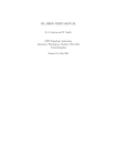
Component Overview
The SPARC64 V processor contains these components.
■
■
■
■
Instruction control Unit (IU)
Execution Unit (EU)
Storage Unit (SU)
Secondary cache and eXternal access Unit (SXU)
FIGURE 1-1 illustrates the major units; the following subsections describe them.
4
SPARC JPS1 Implementation Supplement: Fujitsu SPARC64 V • Release 1.0, 1 July 2002
Extended UPA Bus
E-Unit
SX-Unit
UPA interface logic
MoveIn buffer
MoveOut buffer
U2$
tag
U2$ data
2M 4-way
S-Unit interface
S-Unit
SX interface
ALUs
ALU
Input
Registers
and
Output
Registers
EXA
EXB
FLA
FLB
EAGA
EAGB
SX order queue Store queue
I-TLB
tag
data
2048
+ 32
entry
Level-1 I cache
128 KB, 2-way
D-TLB
2048
+ 32
entry
tag
GUB
FUB
GPR
FPR
data
Level-1 D cache
128 KB, 2-way
I-Unit
Instruction
fetch
pipeline
Instruction
buffer
Commit stack entry
Reservation stations
E-unit
control
logic
PC
nPC
CCR
FSR
Branch
history
FIGURE 1-1
SPARC64 V Major Units
Release 1.0, 1 July 2002
F. Chapter 1
Overview
5
1.3.2
Instruction Control Unit (IU)
The IU predicts the instruction execution path, fetches instructions on the predicted
path, distributes the fetched instructions to appropriate reservation stations, and
dispatches the instructions to the execution pipeline. The instructions are executed
out of order, and the IU commits the instructions in order. Major blocks are defined
in TABLE 1-1.
TABLE 1-1
1.3.3
Instruction Control Unit Major Blocks
Name
Description
Instruction fetch pipeline
Five stages: fetch address generation, iTLB access, iTLB match,
I-Cache fetch, and a write to I-buffer.
Branch history
16K entries, 4-way set associative.
Instruction buffer
Six entries, 32 bytes/entry.
Reservation station
Six reservation stations to hold instructions until they can
execute: RSBR for branch and the other control-transfer
instructions; RSA for load/store instructions; RSEA and RSEB for
integer arithmetic instructions; RSFA and RSFB for floating-point
arithmetic and VIS instructions.
Commit stack entries
Sixty-four entries; basically one instruction/entry, to hold
information about instructions issued but not yet committed.
PC, nPC, CCR, FSR
Program-visible registers for instruction execution control.
Execution Unit (EU)
The EU carries out execution of all integer arithmetic, logical, shift instructions, all
floating-point instructions, and all VIS graphic instructions. TABLE 1-2 describes the
EU major blocks.
TABLE 1-2
Execution Unit Major Blocks
Name
Description
General register (gr) renaming
register file (GUB: gr update
buffer)
Thirty-two entries, 8 read ports, 2 write ports
Gr architecture register file (GPR) 160 entries, 1 read port, 2 write ports
Floating-point (fr) renaming
register file (FUB: fr update
buffer)
Thirty-two entries, 8 read ports, 2 write ports
Fr architecture register file (FPR) Thirty-two entries,
6 read ports, 2 write ports
EU control logic
6
Controls the instruction execution stages: instruction
selection, register read, and execution.
SPARC JPS1 Implementation Supplement: Fujitsu SPARC64 V • Release 1.0, 1 July 2002
TABLE 1-2
Execution Unit Major Blocks (Continued)
Name
Description
Interface registers
Input/output registers to other units.
Two integer execution pipelines
(EXA, EXB)
64-bit ALU and shifters.
Two floating-point and graphics Each floating-point execution pipeline can execute floating
execution pipelines (FLA, FLB) point multiply, floating point add/sub, floating-point
multiply and add, floating point div/sqrt, and floatingpoint graphics instruction.
Two virtual address adders for
memory access pipeline (EAGA,
EAGB)
1.3.4
Two 64-bit virtual addresses for load/store.
Storage Unit (SU)
The SU handles all sourcing and sinking of data for load and store instructions.
TABLE 1-3 describes the SU major blocks.
TABLE 1-3
Storage Unit Major Blocks
Name
Description
Instruction level-1 cache
128-Kbyte, 2-way associative, 64-byte line; provides low latency
instruction source
Data level-1 cache
128-Kbyte, 2-way associative, 64-byte line, writeback; provides
the low latency data source for loads and stores.
Instruction Translation
Buffer
1024 entries, 2-way associative TLB for 8-Kbyte pages,
1024 entries, 2-way associative TLB for 4-Mbyte pages1,
32 entries, fully associative TLB for unlocked 64-Kbyte, 512Kbyte, 4-Mbyte1 pages and locked pages in all sizes.
Data Translation Buffer
1024 entries, 2-way associative TLB for 8-Kbyte pages,
1024 entries, 2-way associative TLB for 4-Mbyte pages1,
32 entries, fully associative TLB for unlocked 64-Kbyte, 512Kbyte, 4-Mbyte1 pages and locked pages in all sizes.
Store queue
Decouples the pipeline from the latency of store operations.
Allows the pipeline to continue flowing while the store waits for
data, and eventually writes into the data level 1 cache.
1. Unloced 4-Mbyte page entry is stored either in 2-way associative TLB or fully associative
TLB exclusively, depending on the setting.
Release 1.0, 1 July 2002
F. Chapter 1
Overview
7
1.3.5
Secondary Cache and External Access Unit (SXU)
The SXU controls the operation of unified level-2 caches and the external data access
interface (extended UPA interface). TABLE 1-4 describes the major blocks of the SXU.
TABLE 1-4
8
Secondary Cache and External Access Unit Major Blocks
Name
Description
Unified level-2 cache
2-Mbyte, 4-way associative, 64-byte line, writeback; provides low
latency data source for both instruction level-1 cache and data
level-1 cache.
Movein buffer
Sixteen entries, 64-bytes/entry; catches returning data from
memory system in response to the cache line read request. A
maximum of 16 outstanding cache read operations can be issued.
Moveout buffer
Eight entries, 64-bytes/entry; holds writeback data. A maximum
of 8 outstanding writeback requests can be issued.
Extended UPA interface
control logic
Send/receive transaction packets to/from Extended UPA
interface connected to the system.
SPARC JPS1 Implementation Supplement: Fujitsu SPARC64 V • Release 1.0, 1 July 2002
F. C H A P T E R
2
Definitions
This chapter defines concepts unique to the SPARC64 V, the Fujitsu implementation
of SPARC JPS1. For definition of terms that are common to all implementations,
please refer to Chapter 2 of Commonality.
committed
Term applied to an instruction when it has completed without error and all
prior instructions have completed without error and have been committed. When
an instruction is committed, the state of the machine is permanently changed
to reflect the result of the instruction; the previously existing state is no longer
needed and can be discarded.
completed
Term applied to an instruction after it has finished, has sent a nonerror status to
the issue unit, and all of its source operands are nonspeculative. Note:
Although the state of the machine has been temporarily altered by completion
of an instruction, the state has not yet been permanently changed and the old
state can be recovered until the instruction has been committed.
executed
Term applied to an instruction that has been processed by an execution unit
such as a load unit. An instruction is in execution as long as it is still being
processed by an execution unit.
fetched
Term applied to an instruction that is obtained from the I2 instruction cache or
from the on-chip internal cache and sent to the issue unit.
finished
Term applied to an instruction when it has completed execution in a functional
unit and has forwarded its result onto a result bus. Results on the result bus are
transferred to the register file, as are the waiting instructions in the instruction
queues.
initiated
Term applied to an instruction when it has all of the resources that it needs (for
example, source operands) and has been selected for execution.
instruction dispatch
instruction issued
Synonym: instruction initiation.
Term applied to an instruction when it has been dispatched to a reservation
station.
9
instruction retired
instruction stall
issue-stalling
instruction
machine sync
Memory Management
Unit (MMU)
Term applied to an instruction that is not allowed to be issued. Not every
instruction can be issued in a given cycle. The SPARC64 V implementation
imposes certain issue constraints based on resource availability and program
requirements.
An instruction that prevents new instructions from being issued until it has
committed.
The state of a machine when all previously executing instructions have
committed; that is, when no issued but uncommitted instructions are in the
machine.
Refers to the address translation hardware in SPARC64 V that translates 64-bit
virtual address into physical address. The MMU is composed of the mITLB,
mDTLB, uITLB, uDTLB, and the ASI registers used to manage address
translation.
mTLB
Main TLB. Split into I and D, called mITLB and mDTLB, respectively. Contains
address translations for the uITLB and uDTLB. When the uITLB or uDTLB do
not contain a translation, they ask the mTLB for the translation. If the mTLB
contains the translation, it sends the translation to the respective uTLB. If the
mTLB does not contain the translation, it generates a fast access exception to a
software translation trap handler, which will load the translation information
(TTE) into the mTLB and retry the access. See also TLB.
uDTLB
Micro Data TLB. A small, fully associative buffer that contains address
translations for data accesses. Misses in the uDTLB are handled by the mTLB.
uITLB
Micro Instruction TLB. A small, fully associative buffer that contains address
translations for instruction accesses. Misses in the uTLB are handled by the
mTLB.
nonspeculative
reclaimed
rename registers
10
Term applied to an instruction when all machine resources (serial numbers,
renamed registers) have been reclaimed and are available for use by other
instructions. An instruction can only be retired after it has been committed.
A distribution system whereby a result is guaranteed known correct or an
operand state is known to be valid. SPARC64 V employs speculative
distribution, meaning that results can be distributed from functional units
before the point at which guaranteed validity of the result is known.
The status when all instruction-related resources that were held until commit
have been released and are available for subsequent instructions. Instruction
resources are usually reclaimed a few cycles after they are committed.
A large set of hardware registers implemented by SPARC64 V that are invisible
to the programmer. Before instructions are issued, source and destination
registers are mapped onto this set of rename registers. This allows instructions
that normally would be blocked, waiting for an architected register, to proceed
SPARC JPS1 Implementation Supplement: Fujitsu SPARC64 V • Release 1.0, 1 July 2002
in parallel. When instructions are committed, results in renamed registers are
posted to the architected registers in the proper sequence to produce the correct
program results.
scan
A method used to initialize all of the machine state within a chip. In a chip that
has been designed to be scannable, all of the machine state is connected in one
or several loops called “scan rings.” Initialization data can be scanned into the
chip through the scan rings. The state of the machine also can be scanned out
through the scan rings.
reservation station
A holding location that buffers dispatched instructions until all input operands
are available. SPARC64 V implements dataflow execution based on operand
availability. When operands are available, the instructions in the reservation
station are scheduled for execution. Reservation stations also contain special
tag-matching logic that captures the appropriate operand data. Reservation
stations are sometimes referred to as queues (for example, the integer queue).
speculative
A distribution system whereby a result is not guaranteed as known to be
correct or an operand state is not known to be valid. SPARC64 V employs
speculative distribution, meaning results can be distributed from functional
units before the point at which guaranteed validity of the result is known.
superscalar
An implementation that allows several instructions to be issued, executed, and
committed in one clock cycle. SPARC64 V issues up to 4 instructions per clock
cycle.
sync
syncing instruction
TLB
Release 1.0, 1 July 2002
Synonym: machine sync.
An instruction that causes a machine sync. Thus, before a syncing instruction is
issued, all previous instructions (in program order) must have been committed.
At that point, the syncing instruction is issued, executed, completed, and
committed by itself.
Translation lookaside buffer.
F. Chapter 2
Definitions
11
12
SPARC JPS1 Implementation Supplement: Fujitsu SPARC64 V • Release 1.0, 1 July 2002
F. C H A P T E R
3
Architectural Overview
Please refer to Chapter 3 in the Commonality section of SPARC Joint Programming
Specification.
13
14
SPARC JPS1 Implementation Supplement: Fujitsu SPARC64 V • Release 1.0, 1 July 2002
F. C H A P T E R
4
Data Formats
Please refer to Chapter 4, Data Formats in Commonality.
15
16
SPARC JPS1 Implementation Supplement: Fujitsu SPARC64 V • Release 1.0, 1 July 2002
F. C H A P T E R
5
Registers
The SPARC64 V processor includes two types of registers: general-purpose—that is,
working, data, control/status—and ASI registers.
The SPARC V9 architecture also defines two implementation-dependent registers:
the IU Deferred-Trap Queue and the Floating-Point Deferred-Trap Queue (FQ);
SPARC64 V does not need or contain either queue. All processor traps caused by
instruction execution are precise, and there are several disrupting traps caused by
asynchronous events, such as interrupts, asynchronous error conditions, and
RED_state entry traps.
For general information, please see parallel subsections of Chapter 5 in
Commonality. For easier referencing, this chapter follows the organization of
Chapter 5 in Commonality.
For information on MMU registers, please refer to Section F.10, Internal Registers and
ASI operations, on page 92.
The chapter contains these sections:
■
■
5.1
Nonprivileged Registers on page 17
Privileged Registers on page 19
Nonprivileged Registers
Most of the definitions for the registers are as described in the corresponding
sections of Commonality. Only SPARC64 V-specific features are described in this
section.
17
5.1.7
Floating-Point State Register (FSR)
Please refer to Section 5.1.7 of Commonality for the description of FSR.
The sections below describe SPARC64 V-specific features of the FSR register.
FSR_nonstandard_fp (NS)
SPARC V9 defines the FSR.NS bit which, when set to 1, causes the FPU to produce
implementation-dependent results that may not conform to IEEE Std 754-1985.
SPARC64 V implements this bit.
When FSR.NS = 1, denormal input operands and denormal results that would
otherwise trap are flushed to 0 of the same sign and an inexact exception is signalled
(that may be masked by FSR.TEM.NXM). See Section B.6, Floating-Point Nonstandard
Mode, on page 61 for details.
When FSR.NS = 0, the normal IEEE Std 754-1985 behavior is implemented.
FSR_version (ver)
For each SPARC V9 IU implementation (as identified by its VER.impl field), there
may be one or more FPU implementations or none. This field identifies the
particular FPU implementation present. For the first SPARC64 V, FSR.ver = 0 (impl.
dep. #19); however, future versions of the architecture may set FSR.ver to other
values. Consult the SPARC64 V Data Sheet for the setting of FSR.ver for your
chipset.
FSR_floating-point_trap_type (ftt)
The complete conditions under which SPARC64 V triggers fp_exception_other with
trap type unfinished_FPop is described in Section B.6, Floating-Point Nonstandard Mode,
on page 61 (impl. dep. #248).
FSR_current_exception (cexc)
Bits 4 through 0 indicate that one or more IEEE_754 floating-point exceptions were
generated by the most recently executed FPop instruction. The absence of an
exception causes the corresponding bit to be cleared.
In SPARC64 V, the cexc bits are set according to the following pseudocode:
if (<LDFSR or LDXFSR commits>)
<update using data from LDFSR or LDXFSR>;
else if (<FPop commits with ftt = 0>)
<update using value from FPU>
18
SPARC JPS1 Implementation Supplement: Fujitsu SPARC64 V • Release 1.0, 1 July 2002
else if (<FPop commits
<set one bit in the
else if (<FPop commits
<no change>;
else if (<FPop commits
<no change>;
else
<no change>;
with IEEE_754_exception>)
CEXC field as supplied by FPU>;
with unfinished_FPop error>)
with unimplemented_FPop error>)
FSR Conformance
SPARC V9 allows the TEM, cexc, and aexc fields to be implemented in hardware in
either of two ways (both of which comply with IEEE Std 754-1985). SPARC64 V
follows case (1); that is, it implements all three fields in conformance with IEEE Std
754-1985. See FSR Conformance in Section 5.1.7 of Commonality for more
information about other implementation methods.
5.1.9
Tick (TICK) Register
SPARC64 V implements TICK.counter register as a 63-bit register (impl. dep.
#105).
Implementation Note – On SPARC64 V, the counter part of the value returned
when the TICK register is read is the value of TICK.counter when the RDTICK
instruction is executed. The difference between the counter values read from the
TICK register on two reads reflects the number of processor cycles executed between
the executions of the RDTICK instructions, not their commits. In longer code
sequences, the difference between this value and the value that would have been
obtained when the instructions are committed would have been small.
5.2
Privileged Registers
Please refer to Section 5.2 of Commonality for the description of privileged registers.
5.2.6
Trap State (TSTATE) Register
SPARC64 V implements only bits 2:0 of the TSTATE.CWP field. Writes to bits 4 and 3
are ignored, and reads of these bits always return zeroes.
Release 1.0, 1 July 2002
F. Chapter 5
Registers
19
Note – Spurious setting of the PSTATE.RED bit by privileged software should not
be performed, since it will take the SPARC64 V into RED_state without the
required sequencing.
5.2.9
Version (VER) Register
TABLE 5-1 shows the values for the VER register for SPARC64 V.
TABLE 5-1
VER Register Encodings
Bits
Field
Value
63:48
manuf
000416 (impl. dep. #104)
47:32
impl
5 (impl. dep. #13)
31:24
mask
n (The value of n depends on the processor chip version)
15:8
maxtl
5
4:0
maxwin
7
The manuf field contains Fujitsu’s 8-bit JEDEC code in the lower 8 bits and zeroes in
the upper 8 bits. The manuf, impl, and mask fields are implemented so that they
may change in future SPARC64 V processor versions. The mask field is incremented
by 1 any time a programmer-visible revision is made to the processor. See the
SPARC64 V Data Sheet to determine the current setting of the mask field.
5.2.11
Ancillary State Registers (ASRs)
Please refer to Section 5.2.11 of Commonality for details of the ASRs.
Performance Control Register (PCR) (ASR 16)
SPARC64 V implements the PCR register as described in SPARC JPS1 Commonality,
with additional features as described in this section.
In SPARC64 V, the accessibility of PCR when PSTATE.PRIV = 0 is determined by
PCR.PRIV. If PSTATE.PRIV = 0 and PCR.PRIV = 1, an attempt to execute either
RDPCR or WRPCR will cause a privileged_action exception. If PSTATE.PRIV = 0 and
PCR.PRIV = 0, RDPCR operates without privilege violation and WRPCR causes a
privileged_action exception only when an attempt is made to change (that is, write 1
to) PCR.PRIV (impl. dep. #250).
See Appendix Q, Performance Instrumentation, for a detailed discussion of the PCR
and PIC register usage and event count definitions.
20
SPARC JPS1 Implementation Supplement: Fujitsu SPARC64 V • Release 1.0, 1 July 2002
The Performance Control Register in SPARC64 V is illustrated in FIGURE 5-1 and
described in TABLE 5-2.
0
OVF
63
48 47
0
32 31 27
FIGURE 5-1
TABLE 5-2
NC
OVRO 0
26
25 24
0
SC
22 21 20 18
0
SU
17 16
0
SL
11 10 9
ULRO UT ST PRIV
4
3
2
1
0
SPARC64 V Performance Control Register (PCR) (ASR 16)
PCR Bit Description
Bit
Field
Description
47:32
OVF
Overflow Clear/Set/Status. Used to read counter overflow status (via RDPCR) and clear
or set counter overflow status bits (via WRPCR). PCR.OVF is a SPARC64 V-specific field
(impl. dep. #207).
The following figure depicts the bit layout of SPARC64 V OVF field for four counter
pairs. Counter status bits are cleared on write of 0 to the appropriate OVF bit.
0
15
U3 L3 U2 L2 U1 L1 U0 L0
7
6
5
4
3
2
1
0
26
OVRO
Overflow read-only. Write-only/read-as-zero field specifying PCR.OVF update behavior
for WRPCR.PCR. The OVRO field is implementation -dependent (impl. dep. #207).
WRPCR.PCR with PCR.OVRO = 1 inhibits updating of PCR.OVF for the current write
only. The intention of PCR.OVRO is to write PCR while preserving current PCR.OVF
value. PCR.OVF is maintained internally by hardware, so a subsequent RDPCR.PCR
returns accurate overflow status at the time.
24:22
NC
Number of counter pairs. Three-bit, read-only field specifying the number of counter
pairs, encoded as 0–7 for 1–8 counter pairs (impl. dep. #207).
For SPARC64 V, the hardcoded value of NC is 3 (indicating presence of 4 counter pairs).
SC
Select PIC. In SPARC64 V, three-bit field specifying which counter pair is currently
selected as PIC (ASR 17) and which SU/SL values are visible to software. On write,
PCR.SC selects which counter pair is updated (unless PCR.ULRO is set; see below). On
read, PCR.SC selects which counter pair is to be read through PIC (ASR 17).
16:11
SU
Defined (as S1) in SPARC JPS1 Commonality.
9:4
SL
Defined (as S0) in SPARC JPS1 Commonality.
ULRO
Implementation-dependent field (impl. dep. #207) that specifies whether SU/SL are
read-only. In SPARC64 V, this field is write-only/read-as-zero, specifying update
behavior of SU/SL on write. When PCR.ULRO = 1, SU/SL are considered as read-only;
the values set on PCR.SU/PCR.SL are not written into SU/SL. When PCR.ULRO = 0,
SU/SL are updated. PCR.ULRO is intended to switch visible PIC by writing PCR.SC,
without affecting current selection of SU/SL of that PIC. On PCR read, PCR.SU/PCR.SL
always shows the current setting of the PIC regardless of PCR.ULRO.
20:18
3
2
UT
Defined in SPARC JPS1 Commonality.
1
ST
Defined in SPARC JPS1 Commonality.
Release 1.0, 1 July 2002
F. Chapter 5
Registers
21
PCR Bit Description (Continued)
TABLE 5-2
Bit
Field
Description
0
PRIV
Defined in SPARC JPS1 Commonality, with the additional function of controlling PCR
accessibility as described above (impl. dep. #250).
Performance Instrumentation Counter (PIC) Register (ASR
17)
The PIC register is implemented as described in SPARC JPS1 Commonality.
Four PICs are implemented in SPARC64 V. Each is accessed through ASR 17, using
PCR.SC as a select field. Read/write access to the PIC will access the PICU/PICL
counter pair selected by PCR. For PICU/PICL encodings of specific event counters,
see Appendix Q, Performance Instrumentation.
Counter Overflow. On overflow, counters wrap to 0, SOFTINT register bit 15 is set,
and an interrupt level-15 exception is generated. The counter overflow trap is
triggered on the transition from value FFFF FFFF16 to value 0. If multiple overflows
are generated simultaneously, then multiple overflow status bits will be set. If
overflow status bits are already set, then they remain set on counter overflow.
Overflow status bits are cleared by software writing 0 to the appropriate bit of
PCR.OVF and may be set by writing 1 to the appropriate bit. Setting these bits by
software does not generate a level 15 interrupt.
Dispatch Control Register (DCR) (ASR 18)
The DCR is not implemented in SPARC64 V. Zero is returned on read, and writes to
the register are ignored. The DCR is a privileged register; attempted access by
nonprivileged (user) code generates a privileged_opcode exception.
5.2.12
Registers Referenced Through ASIs
Data Cache Unit Control Register (DCUCR)
ASI 4516 (ASI_DCU_CONTROL_REGISTER), VA = 016.
The Data Cache Unit Control Register contains fields that control several memoryrelated hardware functions. The functions include Instruction, Prefetch, write and
data caches, MMUs, and watchpoint setting. SPARC64 V implements most of
DCUCUR’s functions described in Section 5.2.12 of Commonality.
22
SPARC JPS1 Implementation Supplement: Fujitsu SPARC64 V • Release 1.0, 1 July 2002
After a power-on reset (POR), all fields of DCUCR, including implementationdependent fields, are set to 0. After a WDR, XIR, or SIR reset, all fields of DCUCR,
including implementation-dependent fields, are set to 0.
The Data Cache Unit Control Register is illustrated in FIGURE 5-2 and described in
TABLE 5-3. In the table, bits are grouped by function rather than by strict bit sequence.
—
63
50
Implementation dependent
0
0
49
48 47
42
FIGURE 5-2
WEAK_SPCA
41
PM
VM
PR
40 33 32 25 24
PW VR
23
22
VW
21 20
—
4
DM
IM
3
2
0
1
0
0
DCU Control Register Access Data Format (ASI 4516)
DCUCR Description
TABLE 5-3
Bits
Field
Type
Use — Description
49:48
CP, CV
RW
Not implemented in SPARC64 V (impl. dep. #232). It reads as 0 and writes to
it are ignored.
47:42
impl. dep.
41
WEAK_SPCA
Not used. It reads as 0 and writes to it are ignored.
RW
Used for disabling speculative memory access (impl. dep. #240). When
DCUCR.WEAK_SPCA = 1, the branch history table is cleared and no longer
issues aggressive instruction prefetch.
During DCUCR.WEAK_SPCA = 1, aggressive instruction prefetching is
disabled and any load and store instructions are considered presync
instructions that are executed when all previous instructions are committed.
Because all CTI are considered as not taken, instructions residing beyond 1
Kbyte of a CTI may be fetched and executed.
On entering aggressive instruction Prefetch disable mode, supervisor
software should issue membar #Sync, to make sure all in-flight instructions
in the pipeline are discarded.
During DCUCR.WEAK_SPCA = 1, an L2 cache flush by writing 1 to
ASI_L2_CTRL.U2_FLUSH remains pending internally until
DCUCR.WEAK_SPCA is set to 0. To wait for completion of the cache flush, a
member #Sync must be issued after DCUCR.WEAK_SPCA is set to 0.
Executing a membar #Sync while the DCUCR.WEAK_SPCA = 1 after writing 1
to ASI_L2_CTRL.U2_FLUSH does not wait for the cache flush to complete.
40:33
PM<7:0>
Defined in SPARC JPS1 Commonality.
32:25
VM<7:0>
Defined in SPARC JPS1 Commonality.
24, 23
PR, PW
Defined in SPARC JPS1 Commonality.
22, 21
VR, VW
Defined in SPARC JPS1 Commonality.
20:4
—
Reserved.
3
DM
Defined in SPARC JPS1 Commonality.
2
IM
Defined in SPARC JPS1 Commonality.
Release 1.0, 1 July 2002
F. Chapter 5
Registers
23
DCUCR Description (Continued)
TABLE 5-3
Bits
Field
Type
Use — Description
1
DC
RW
Not implemented in SPARC64 V (impl. dep. #252). It reads as 0 and writes to
it are ignored.
0
IC
RW
Not implemented in SPARC64 V (impl. dep. #253). It reads as 0 and writes to
it are ignored.
Data Watchpoint Registers
No implementation-dependent feature of SPARC64 V reduces the reliability of data
watchpoints (impl. dep. #244).
SPARC64 V employs conservative check of PA/VA watchpoint over partial store
instruction. See Section A.42, Partial Store (VIS I), on page 57 for details.
Instruction Trap Register
SPARC64 V implements the Instruction Trap Register (impl. dep. #205).
In SPARC64 V, the least significant 11 bits (bits 10:0) of a CALL or branch (BPcc,
FBPfcc, Bicc, BPr) instruction in an instruction cache are identical to their
architectural encoding (as it appears in main memory) (impl. dep. #245).
5.2.13
Floating-Point Deferred-Trap Queue (FQ)
SPARC64 V does not contain a Floating-Point Deferred-trap Queue (impl. dep. #24).
An attempt to read FQ with an RDPR instruction generates an illegal_instruction
exception (impl. dep. #25).
5.2.14
IU Deferred-Trap Queue
SPARC64 V neither has nor needs an IU deferred-trap queue (impl. dep. #16)
24
SPARC JPS1 Implementation Supplement: Fujitsu SPARC64 V • Release 1.0, 1 July 2002
F. C H A P T E R
6
Instructions
This chapter presents SPARC64 V implementation-specific instruction details and the
processor pipeline information in these subsections:
■
■
■
■
Instruction Execution on page 25
Instruction Formats and Fields on page 28
Instruction Categories on page 29
Processor Pipeline on page 31
For additional, general information, please see parallel subsections of Chapter 6 in
Commonality. For easy referencing, we follow the organization of Chapter 6 in
Commonality.
6.1
Instruction Execution
SPARC64 V is an advanced superscalar implementation of SPARC V9. Several
instructions may be issued and executed in parallel. Although SPARC64 V provides
serial program execution semantics, some of the implementation characteristics
described below are part of the architecture visible to software for correctness and
efficiency. The affected software includes optimizing compilers and supervisor code.
6.1.1
Data Prefetch
SPARC64 V employs speculative (out of program order) execution of instructions; in
most cases, the effect of these instructions can be undone if the speculation proves to
be incorrect.1 However, exceptions can occur because of speculative data
prefetching. Formally, SPARC64 V employs the following rules regarding speculative
prefetching:
1. An async_data_error may be signalled during speculative data prefetching.
25
1. If a memory operation y resolves to a volatile memory address (location[y]),
SPARC64 V will not speculatively prefetch location[y] for any reason; location[y]
will be fetched or stored to only when operation y is commitable.
2. If a memory operation y resolves to a nonvolatile memory address (location[y]),
SPARC64 V may speculatively prefetch location[y] subject, adhering to the
following subrules:
a. If an operation y can be speculatively prefetched according to the prior rule,
operations with store semantics are speculatively prefetched for ownership
only if they are prefetched to cacheable locations. Operations without store
semantics are speculatively prefetched even if they are noncacheable as long as
they are not volatile.
b. Atomic operations (CAS(X)A, LDSTUB, SWAP) are never speculatively
prefetched.
SPARC64 V provides two mechanisms to avoid speculative execution of a load:
1. Avoid speculation by disallowing speculative accesses to certain memory pages or
I/O spaces. This can be done by setting the E (side-effect) bit in the PTE for all
memory pages that should not allow speculation. All accesses made to memory
pages that have the E bit set in their PTE will be delayed until they are no longer
speculative or until they are cancelled. See Appendix F, Memory Management Unit,
for details.
2. Alternate space load instructions that force program order, such as
ASI_PHYS_BYPASS_WITH_EBIT[_L] (AS I = 1516, 1D16), will not be speculatively
executed.
6.1.2
Instruction Prefetch
The processor prefetches instructions to minimize cases where the processor must
wait for instruction fetch. In combination with branch prediction, prefetching may
cause the processor to access instructions that are not subsequently executed. In
some cases, the speculative instruction accesses will reference data pages.
SPARC64 V does not generate a trap for any exception that is caused by an
instruction fetch until all of the instructions before it (in program order) have been
committed.1
1. Hardware errors and other asynchronous errors may generate a trap even if the instruction that caused the
trap is never committed.
26
SPARC JPS1 Implementation Supplement: Fujitsu SPARC64 V • Release 1.0, 1 July 2002
6.1.3
Syncing Instructions
SPARC64 V has instructions, called syncing instructions, that stop execution for the
number of cycles it takes to clear the pipeline and to synchronize the processor.
There are two types of synchronization, pre and post. A presyncing instruction waits
for all previous instructions to commit, commits by itself, and then issues successive
instructions. A postsyncing instruction issues by itself and prevents the successive
instructions from issuing until it is committed. Some instructions have both pre- and
postsync attributes.
In SPARC64 V almost all instructions commit in order, but store instruction commit
before becoming globally visible. A few syncing instructions cause the processor to
discard prefetched instructions and to refetch the successive instructions. TABLE 6-1
lists all pre-/postsync instructions and the effects of instruction execution.
TABLE 6-1
SPARC64 V Syncing Instructions
Presyncing
Opcode
Sync?
Wait for
store global
visibility?
Postsyncing
Sync?
ALIGNADDRESS{_LITTLE}
Yes
BMASK
Yes
DONE
FCMP(GT,LE,NE,EQ)(16,32)
Yes
Yes
Yes
Yes
Yes
FLUSH
Yes
FMOV(s,d)icc
Yes
FMOVr
Yes
LDD
Yes
Yes
LDDA
Yes
Yes
LDDFA
Yes
memory access with
ASI=ASI_PHYS_BYPASS_EC{_LITTLE},
ASI_PHYS_BYPASS_EC_WITH_E_BIT{_LITTLE}
Yes
Yes
LDFSR, LDXFSR
MEMBAR
Yes
MOVfcc
Yes
MULScc
Yes
Yes1
Yes
Yes
PDIST
RDASR
Yes
RETRY
Yes
SIAM
Yes
STBAR
Yes
STD
Yes
Release 1.0, 1 July 2002
Discard
prefetched
instructions?
F. Chapter 6
Yes
Instructions
27
TABLE 6-1
SPARC64 V Syncing Instructions (Continued)
Presyncing
Opcode
Sync?
Postsyncing
Wait for
store global
visibility?
Sync?
Discard
prefetched
instructions?
Yes
Yes
STDA
STDFA
Yes
STFSR, STXFSR
Yes
Tcc
Yes
Yes
WRASR
Yes2
Yes
1. When #cmask ! = 0.
2. WRGSR only.
6.2
Instruction Formats and Fields
Instructions are encoded in five major 32-bit formats and several minor formats.
Please refer to Section 6.2 of Commonality for illustrations of four major formats.
FIGURE 6-1 illustrates Format 5, unique to SPARC64 V.
Format 5 (op = 2, op3 = 3716): FMADD, FMSUB, FNMADD, and FNMSUB (in place of IMPDEP2B)
op
rd
op3
31 30 29
25 24
rs1
19 18 17
FIGURE 6-1
rs3
14 13 12
11 10
var
9
8
7
size
6
5
rs2
4
0
Summary of Instruction Formats: Format 5
Instruction fields are those shown in Section 6.2 of Commonality. Three additional
fields are implemented in SPARC64 V. They are described in TABLE 6-2.
TABLE 6-2
28
Instruction Fields Specific to SPARC64 V
Bits
Field
Description
13:9
rs3
This 5-bit field is the address of the third f register source operand for
the floating-point multiply-add and multiply-subtract instruction.
8.7
var
This 2-bit field specifies which specific operation (variation) to perform
for the floating-point multiply-add and multiply-subtract instructions
6.5
size
This 2-bit field specifies the size of the operands for the floating-point
multiply-add and multiply-subtract instructions.
SPARC JPS1 Implementation Supplement: Fujitsu SPARC64 V • Release 1.0, 1 July 2002
Since size = 00 is not IMPDEP2B and since size = 11 assumed quad operations but
is not implemented in SPARC64 V, the instruction with size = 00 or 11 generates an
illegal_instruction exception in SPARC64 V.
6.3
Instruction Categories
SPARC V9 instructions comprise the categories listed below. All categories are
described in Section 6.3 of Commonality. Subsections in bold face are SPARC64 V
implementation dependencies.
■
■
■
■
■
■
■
■
■
■
6.3.3
Memory access
Memory synchronization
Integer arithmetic
Control transfer (CTI)
Conditional moves
Register window management
State register access
Privileged register access
Floating-point operate (FPop)
Implementation-dependent
Control-Transfer Instructions (CTIs)
These are the basic control-transfer instruction types:
■
■
■
■
■
■
Conditional branch (Bicc, BPcc, BPr, FBfcc, FBPfcc)
Unconditional branch
Call and link (CALL)
Jump and link (JMPL, RETURN)
Return from trap (DONE, RETRY)
Trap (Tcc)
Instructions other than CALL and JMPL are described in their entirety in Section 6.3.2
of Commonality. SPARC64 V implements CALL and JMPL as described below.
CALL and JMPL Instructions
SPARC64 V writes all 64 bits of the PC into the destination register when
PSTATE.AM = 0. The upper 32 bits of r[15] (CALL) or of r[rd] (JMPL) are written
as zeroes when PSTATE.AM = 1 (impl. dep. #125).
Release 1.0, 1 July 2002
F. Chapter 6
Instructions
29
SPARC64 V implements JMPL and CALL return prediction hardware in a form of
special stack, called the Return Address Stack (RAS). Whenever a CALL or JMPL that
writes to %o7 (r[15]) occurs, SPARC64 V “pushes” the return address (PC+8) onto
the RAS. When either of the synthetic instructions retl (JMPL [%o7+8]) and ret (JMPL
[%i7+8]) are subsequently executed, the return address is predicted to be the
address stored on the top of the RAS and the RAS is “popped.” If the prediction in
the RAS is incorrect, SPARC64 V backs up and starts issuing instructions from the
correct target address. This backup takes a few extra cycles.
Programming Note – For maximum performance, software and compilers must
take into account how the RAS works. For example, tricks that do nonstandard
returns in hopes of boosting performance may require more cycles if they cause the
wrong RAS value to be used for predicting the address of the return. Heavily nested
calls can also cause earlier entries in the RAS to be overwritten by newer entries,
since the RAS only has a limited number of entries. Eventually, some return
addresses will be mispredicted because of the overflow of the RAS.
6.3.7
Floating-Point Operate (FPop) Instructions
The complete conditions of generating an fp_exception_other exception with
FSR.ftt = unfinished_FPop are described in Section B.6, Floating-Point Nonstandard
Mode on page 61.
The SPARC64 V-specific FMADD and FMSUB instructions (described below) are also
floating-point operations. They require the floating-point unit to be enabled;
otherwise, an fp_disabled trap is generated. They also affect the FSR, like FPop
instructions. However, these instructions are not included in the FPop category and,
hence, reserved encodings in these opcodes generate an illegal_instruction exception, as
defined in Section 6.3.9 of Commonality.
6.3.8
Implementation-Dependent Instructions
SPARC64 V uses the IMPDEP2 instruction to implement the Floating-Point MultiplyAdd/Subtract and Negative Multiply-Add/Subtract instructions; these have an op3
field = 3716 (IMPDEP2). See Floating-Point Multiply-Add/Subtract on page 50 for fuller
definitions of these instructions. Opcode space is reserved in IMPDEP2 for the quadprecision forms of these instructions. However, SPARC64 V does not currently
implement the quad-precision forms, and the processor generates an illegal_instruction
exception if a quad-precision form is specified. Since these instructions are not part
of the required SPARC V9 architecture, the operating system does not supply
software emulation routines for the quad versions of these instructions.
SPARC64 V uses the IMPDEP1 instruction to implement the graphics acceleration
instructions.
30
SPARC JPS1 Implementation Supplement: Fujitsu SPARC64 V • Release 1.0, 1 July 2002
6.4
Processor Pipeline
The pipeline of SPARC64 V consists of fifteen stages, shown in FIGURE 6-2. Each
stage is referenced by one or two letters as follows:
IA
IT
IM
IB
IR
E
D
P
B
X
Ps
6.4.1
U
Ts
Ms
Bs
W
Rs
Instruction Fetch Stages
■
IA (Instruction Address generation) — Calculate fetch target address.
■
IT (Instruction TLB Tag access) — Instruction TLB tag search. Search of BRHIS
and RAS is also started.
■
IM (Instruction TLB tag Match) — Check TLB tag is matched.
The result of BRHIS and RAS search is also available at this stage and is
forwarded to IA stage for subsequent fetch.
■
IB (Instruction cache Buffer read) — Read L1 cache data if TLB is hit.
■
IR (Instruction read Result) — Write to I-Buffer.
IA through IR stages are dedicated to instruction fetch. These stages work in concert
with the cache access unit to supply instructions to subsequent stages. The
instructions fetched from memory or cache are stored in the Instruction Buffer (Ibuffer). The I-buffer has six entries, each of which can hold 32-byte-aligned 32-byte
data (eight instructions).
SPARC64 V has a branch prediction mechanism and resources named BRHIS
(BRanch HIStory) and RAS (Return Address Stack). Instruction fetch stages use these
resources to determine fetch addresses.
Instruction fetch stages are designed so that they work independently of subsequent
stages as much as possible. And they can fetch instructions even when execution
stages stall. These stages fetch until the I-Buffer is full; further fetches are possible by
requesting prefetches to the L1 cache.
Release 1.0, 1 July 2002
F. Chapter 6
Instructions
31
IF EAG
IA
IT
BRHIS
iTLB
IM
L1I
IB
Instruction Buffer
E IR
IWR
D
RSFA
RSFB
RSEA
RSEB
RSA
RSBR
P
CSE
B
FXB
FXA
EXB
EXA
EAGA
EAGB
Ps
RR
RR
RR
X
RR
Ts
FUB
GUB
dTLB
Ms
L1D
Bs
LB
Rs
LR
U
W
FPR
GPR
FIGURE 6-2
32
ccr fsr
PC nPC
SPARC64 V Pipeline
SPARC JPS1 Implementation Supplement: Fujitsu SPARC64 V • Release 1.0, 1 July 2002
6.4.2
Issue Stages
■
E (Entry) — Instructions are passed from fetch stages.
■
D (Decode) — Assign resources and dispatch to reservation station (RS.)
SPARC64 V is an out-of-order execution CPU. It has six execution units (two of
arithmetic and logic unit, two of floating-point unit, two of load/store unit). Each
unit except the load/store unit has its own reservation station. E and D stages are
issue stages that decode instructions and dispatch them to the target RS. SPARC64 V
can issue up to four instructions per cycle.
The resources needed to execute an instruction are assigned in the issue stages. The
resources to be allocated include the following:
■
Commit stack entry (CSE)
■
Renaming registers of integer (GUB) and floating-point (FUB)
■
Entries of reservations stations
■
Memory access ports
Resources needed for an instruction are specific to the instruction, but all resources
must be assigned at these stages. In normal execution, assigned resources are
released at the very last stage of the pipeline, W-stage.1 Instructions between the Estage and W-stage are considered to be in-flight. When an exception is signalled, all
in-flight instructions and the resources used by them are released immediately. This
behavior enables the decoder to restart issuing instructions as quickly as possible.
The number of in-flight instructions depends on how many resources are needed by
them. The maximum number is 64.
6.4.3
Execution Stages
■
P (priority) — Select an instruction from those that have met the conditions for
execution.
■
B (buffer read) — Read register file, or receive forwarded data from another
pipelines.
■
X (execute) — Execution.
Instructions in reservation stations will be executed when certain conditions are met,
for example, the values of source registers are known, the execution unit is available.
Execution latency varies from one to many, depending on the instruction.
1. An entry in a reservation station is released at the X-stage.
Release 1.0, 1 July 2002
F. Chapter 6
Instructions
33
Execution Stages for Cache Access
Memory access requests are passed to the cache access pipeline after the target
address is calculated. Cache access stages work the same way as instruction fetch
stages, except for the handling of branch prediction. See Section 6.4.1, Instruction
Fetch Stages, for details. Stages in instruction fetch and cache access correspond as
follows:
Instruction Fetch Stages
Cache Access
IA
Ps
IT
Ts
IM
Ms
IB
Bs
IR
Rs
When an exception is signalled, fetch ports and store ports used by memory access
instructions are released. The cache access pipeline itself remains working in order to
complete outgoing memory accesses. When data is returned, it is then stored to the
cache.
6.4.4
Completion Stages
■
U (Update) — Update of physical (renamed) register.
■
W (Write) — Update of architectural registers and retire; exception handling.
■
After an out-of-order execution, execution reverts to program order to complete.
Exception handling is done in the completion stages. Exceptions occurring in
execution stages are not handled immediately but are signalled when the
instruction is completed.1
1. RAS-related exception may be signalled before completion.
34
SPARC JPS1 Implementation Supplement: Fujitsu SPARC64 V • Release 1.0, 1 July 2002
F. C H A P T E R
7
Traps
Please refer to Chapter 7 of Commonality. Section numbers in this chapter
correspond to those in Chapter 7 of Commonality.
This chapter adds SPARC64 V-specific information in the following sections:
■
■
■
■
■
7.1
Processor States, Normal and Special Traps on page 35
■
RED_state on page 36
■
error_state on page 36
Trap Categories on page 37
■
Deferred Traps on page 37
■
Reset Traps on page 37
■
Uses of the Trap Categories on page 37
Trap Control on page 38
■
PIL Control on page 38
Trap-Table Entry Addresses on page 38
■
Trap Type (TT) on page 38
■
Details of Supported Traps on page 39
Exception and Interrupt Descriptions on page 39
Processor States, Normal and Special
Traps
Please refer to Section 7.1 of Commonality.
35
7.1.1
RED_state
RED_state Trap Table
The RED_state trap vector is located at an implementation-dependent address
referred to as RSTVaddr. The value of RSTVaddr is a constant within each
implementation; in SPARC64 V this virtual address is FFFF FFFF F000 000016,
which translates to physical address 0000 07FF F000 000016 in RED_state (impl.
dep. #114).
RED_state Execution Environment
In RED_state, the processor is forced to execute in a restricted environment by
overriding the values of some processor controls and state registers.
Note – The values are overridden, not set, allowing them to be switched atomically.
SPARC64 V has the following implementation-dependent behavior in RED_state
(impl. dep. #115):
■
While in RED_state, all internal ITLB-based translation functions are disabled.
DTLB-based translations are disabled upon entry but may be reenabled by
software while in RED_state. However, ASI-based access functions to the TLBs
are still available.
■
While mTLBs and uTLBs are disabled, all accesses are assumed to be
noncacheable and strongly ordered for data access.
■
XIR errors are not masked and can cause a trap.
Note – When RED_state is entered because of component failures, the handler
should attempt to recover from potentially catastrophic error conditions or to disable
the failing components. When RED_state is entered after a reset, the software
should create the environment necessary to restore the system to a running state.
7.1.2
error_state
The processor enters error_state when a trap occurs while the processor is
already at its maximum supported trap level (that is, when TL = MAXTL) (impl. dep.
#39).
36
SPARC JPS1 Implementation Supplement: Fujitsu SPARC64 V • Release 1.0, 1 July 2002
Although the standard behavior of the CPU upon an entry into error_state is to
internally generate a watchdog_reset (WDR), the CPU optionally stays halted upon an
entry to error_state depending on a setting in the OPSR register (impl. dep #40,
#254).
7.2
Trap Categories
Please refer to Section 7.2 of Commonality.
An exception or interrupt request can cause any of the following trap types:
■
■
■
■
7.2.2
Precise trap
Deferred trap
Disrupting trap
Reset trap
Deferred Traps
Please refer to Section 7.2.2 of Commonality.
SPARC64 V implements a deferred trap to signal certain error conditions (impl. dep.
#32). Please refer to the description of I_UGE error on “Relation between %tpc and
the instruction that caused the error” row in TABLE P-2 (page 156) for details. See also
Instruction End-Method at ADE Trap on page 170.
7.2.4
Reset Traps
Please refer to Section 7.2.4 of Commonality.
In SPARC64 V, a watchdog reset (WDR) occurs when the processor has not
committed an instruction for 233 processor clocks.
7.2.5
Uses of the Trap Categories
Please refer to Section 7.2.5 of Commonality.
All exceptions that occur as the result of program execution are precise in
SPARC64 V (impl. dep. #33).
An exception caused after the initial access of a multiple-access load or store
instruction (LDD(A), STD(A), LDSTUB, CASA, CASXA, or SWAP) that causes a
catastrophic exception is precise in SPARC64 V.
Release 1.0, 1 July 2002
F. Chapter 7
Traps
37
7.3
Trap Control
Please refer to Section 7.3 of Commonality.
7.3.1
PIL Control
SPARC64 V receives external interrupts from the UPA interconnect. They cause an
interrupt_vector_trap (TT = 6016). The interrupt vector trap handler reads the interrupt
information and then schedules SPARC V9-compatible interrupts by writing bits in
the SOFTINT register. Please refer to Section 5.2.11 of Commonality for details.
During handling of SPARC V9-compatible interrupts by SPARC64 V, the PIL
register is checked. If an interrupt has sufficient priority, SPARC64 V will stop
issuing new instructions, will flush all uncommitted instructions, and then will
vector to the trap handler. The only exception to this process occurs when
SPARC64 V is processing a higher-priority trap.
SPARC64 V takes a normal disrupting trap upon receipt of an interrupt request.
7.4
Trap-Table Entry Addresses
Please refer to Section 7.4 of Commonality.
7.4.2
Trap Type (TT)
Please refer to Section 7.4.2 of Commonality.
SPARC64 V implements all mandatory SPARC V9 and SPARC JPS1 exceptions, as
described in Chapter 7 of Commonality, plus the exception listed in TABLE 7-1, which
is specific to SPARC64 V (impl. dep. #35; impl. dep. #36).
TABLE 7-1
38
Exceptions Specific to SPARC64 V
Exception or Interrupt Request
TT
Priority
async_data_error
04016
2
SPARC JPS1 Implementation Supplement: Fujitsu SPARC64 V • Release 1.0, 1 July 2002
7.4.4
Details of Supported Traps
Please refer to Section 7.4.4 in Commonality.
SPARC64 V Implementation-Specific Traps
SPARC64 V supports the following implementation-specific trap type:
■
7.5
async_data_error
Trap Processing
Please refer to Section 7.5 of Commonality.
7.6
Exception and Interrupt Descriptions
Please refer to Section 7.6 of Commonality.
7.6.4
SPARC V9 Implementation-Dependent, Optional
Traps That Are Mandatory in SPARC JPS1
Please refer to Section 7.6.4 of Commonality.
SPARC64 V implements all six traps that are implementation dependent in SPARC
V9 but mandatory in JPSI (impl. dep. #35). Se Section 7.6.4 of Commonality for
details.
7.6.5
SPARC JPS1 Implementation-Dependent Traps
Please refer to Section 7.6.5 of Commonality.
SPARC64 V implements the following traps that are implementation dependent
(impl. dep. #35).
■
async_data_error [tt = 04016] (Preemptive or disrupting) (impl. dep. #218) —
SPARC64 V implements the async_data_error exception to signal the following
errors.
Release 1.0, 1 July 2002
F. Chapter 7
Traps
39
■
■
■
■
■
Uncorrectable errors in the internal architecture registers (general registers–gr,
floating-point registers–fr, ASR, ASI registers)
Uncorrectable errors in the core pipeline
System data corruption
Watch dog timeout first time
TLB access error upon access by an ldxa or stxa instruction
Multiple errors may be reported in a single generation of the async_data_error
exception. Depending on the situation, the async_data_error trap becomes a precise
trap, a disrupting trap, or a preemptive trap upon error detection. The TPC and
TNPC stacked by the exception may indicate the exact instruction, the preceding
instruction, or the subsequent instruction inducing the error. See Appendix P for
details of the async_data_error exception in SPARC64 V.
40
SPARC JPS1 Implementation Supplement: Fujitsu SPARC64 V • Release 1.0, 1 July 2002
F. C H A P T E R
8
Memory Models
The SPARC V9 architecture is a model that specifies the behavior observable by
software on SPARC V9 systems. Therefore, access to memory can be implemented in
any manner, as long as the behavior observed by software conforms to that of the
models described in Chapter 8 of Commonality and defined in Appendix D, Formal
Specification of the Memory Models, also in Commonality.
The SPARC V9 architecture defines three different memory models: Total Store Order
(TSO), Partial Store Order (PSO), and Relaxed Memory Order (RMO). All SPARC V9
processors must provide Total Store Order (or a more strongly ordered model, for
example, Sequential Consistency) to ensure SPARC V8 compatibility.
Whether the PSO or RMO models are supported by SPARC V9 systems is
implementation dependent; SPARC64 V behaves in a manner that guarantees
adherence to whichever memory model is currently in effect.
This chapter describes the following major SPARC64 V-specific details of memory
models.
■
SPARC V9 Memory Model on page 42
For general information, please see parallel subsections of Chapter 8 in
Commonality. For easier referencing, this chapter follows the organization of
Chapter 8 in Commonality, listing subsections whether or not there are
implementation-specific details.
41
8.1
Overview
Note – The words “hardware memory model” denote the underlying hardware
memory models as differentiated from the “SPARC V9 memory model,” which is the
memory model the programmer selects in PSTATE.MM.
SPARC64 V supports only one mode of memory handling to guarantee correct
operation under any of the three SPARC V9 memory ordering models (impl. dep.
#113):
■
8.4
Total Store Order — All loads are ordered with respect to loads, and all stores are
ordered with respect to loads and stores. This behavior is a superset of the
requirements for the SPARC V9 memory models TSO, PSO, and RMO. When
PSTATE.MM selects TSO or PSO, SPARC64 V operates in this mode. Since
programs written for PSO (or RMO) will always work if run under Total Store
Order, this behavior is safe but does not take advantage of the reduced restrictions
of PSO.
SPARC V9 Memory Model
Please refer to Section 8.4 of Commonality.
In addition, this section describes SPARC64 V-specific details about the processor/
memory interface model.
8.4.5
Mode Control
SPARC64 V implements Total Store Ordering for all PSTATE.MM. Writing 112 into
PSTATE.MM also causes the machine to use TSO (impl. dep. #119). However, the
encoding 112 should not be used, since future version of SPARC64 V may use this
encoding for a new memory model.
8.4.6
Synchronizing Instruction and Data Memory
All caches in a SPARC64 V-based system (uniprocessor or multiprocessor) have a
unified cache consistency protocol and implement strong coherence between
instruction and data caches. Writes to any data cache cause invalidations to the
42
SPARC JPS1 Implementation Supplement: Fujitsu SPARC64 V • Release 1.0, 1 July 2002
corresponding locations in all instruction caches; references to any instruction cache
cause corresponding modified data to be flushed and corresponding unmodified
data to be invalidated from all data caches. The flush operation is still operative in
SPARC64 V, however.
Since the FLUSH instruction synchronizes the processor, the total latency varies
depending on the situation in SPARC64 V. Assuming all prior instructions are
completed, the latency of FLUSH is 18 CPU cycles.
Release 1.0, 1 July 2002
F. Chapter 8
Memory Models
43
44
SPARC JPS1 Implementation Supplement: Fujitsu SPARC64 V • Release 1.0, 1 July 2002
F. A P P E N D I X
A
Instruction Definitions:
SPARC64 V Extensions
This appendix describes the SPARC64 V-specific implementation of the instructions
in Appendix A of Commonality. If an instruction is not described in this appendix,
then no SPARC64 V implementation-dependency applies.
■
See TABLE A-1 of Commonality for the location at which general information about
the instruction can be found.
■
Section numbers refer to the parallel section numbers in Appendix A of
Commonality.
TABLE A-1 lists four instructions that are unique to SPARC64 V.
TABLE A-1
Implementation-Specific Instructions
Operation
Name
Page
V9 Ext?
FMADD(s,d)
Floating-point multiply add
page 50
✓
FMSUB(s,d)
Floating-point multiply subtract
page 50
✓
FNMADD(s,d)
Floating-point multiply negate add
page 50
✓
FNMSUB(s,d)
Floating-point multiply negate subtract
page 50
✓
Each instruction definition consists of these parts:
1. A table of the opcodes defined in the subsection with the values of the field(s)
that uniquely identify the instruction(s).
2. An illustration of the applicable instruction format(s). In these illustrations a dash
(—) indicates that the field is reserved for future versions of the architecture and
shall be 0 in any instance of the instruction. If a conforming SPARC V9
implementation encounters nonzero values in these fields, its behavior is
undefined.
3. A list of the suggested assembly language syntax, as described in Appendix G,
Assembly Language Syntax.
45
4. A description of the features, restrictions, and exception-causing conditions.
5. A list of exceptions that can occur as a consequence of attempting to execute the
instruction(s). Exceptions due to an instruction_access_error,
instruction_access_exception, fast_instruction_access_MMU_miss, async_data_error,
ECC_error, and interrupts are not listed because they can occur on any instruction.
Also, any instruction that is not implemented in hardware shall generate an
illegal_instruction exception (or fp_exception_other exception with
ftt = unimplemented_FPop for floating-point instructions) when it is executed.
The illegal_instruction trap can occur during chip debug on any instruction that has
been programmed into the processor’s IIU_INST_TRAP (ASI = 6016, VA = 0).
These traps are also not listed under each instruction.
The following traps never occur in SPARC64 V:
■
■
■
■
■
■
■
■
■
instruction_access_MMU_miss
data_access_MMU_miss
data_access_protection
unimplemented_LDD
unimplemented_STD
LDQF_mem_address_not_aligned
STQF_mem_address_not_aligned
internal_processor_error
fp_exception_other (ftt = invalid_fp_register)
This appendix does not include any timing information (in either cycles or clock
time).
The following SPARC64 V-specific extensions are described.
■
■
■
■
■
■
■
■
■
■
■
■
46
Block Load and Store Instructions (VIS I) on page 47
Call and Link on page 49
Implementation-Dependent Instructions on page 49
Jump and Link on page 53
Load Quadword, Atomic [Physical] on page 54
Memory Barrier on page 55
Partial Store (VIS I) on page 57
Prefetch Data on page 57
Read State Register on page 58
SHUTDOWN (VIS I) on page 58
Write State Register on page 59
Deprecated Instructions on page 59
SPARC JPS1 Implementation Supplement: Fujitsu SPARC64 V • Release 1.0, 1 July 2002
A.4
Block Load and Store Instructions (VIS I)
The following notes summarize behavior of block load/store instructions in
SPARC64 V.
1. Block load and store operations are not atomic, in that they are internally
decomposed into eight independent, 8-byte load/store operations in SPARC64 V.
Each load/store is always issued and performed in the RMO memory model and
obeys all prior MEMBAR and atomic instruction-imposed ordering constraints.
2. Block load/store instructions are out of the scope of V9 memory models, meaning
that self-consistency of memory reference instruction is not always maintained if
block load/store instructions are involved in the execution flow. The following
table describes the implemented ordering constraints for block load/store
instructions with respect to the other memory reference instructions with an
operand address conflict in SPARC64 V:
Program Order for conflicting bld/bst/ld/st
first
next
Ordered/
Out-of-Order
store
blockstore
Ordered
store
blockload
Ordered
load
blockstore
Ordered
load
blockload
Ordered
blockstore
store
Out-of-Order
blockstore
load
Out-of-Order
blockstore
blockstore
Out-of-Order
blockstore
blockload
Out-of-Order
blockload
store
Ordered
blockload
load
Ordered
blockload
blockstore
Ordered
blockload
blockload
Ordered
To maintain the memory ordering even for the memory address conflicts, MEMBAR
instructions shall be inserted into appropriate location in the program.
Although self-consistency with respect to the block load/store and the other
memory reference instructions is not maintained in some cases, register conflicts
between the other instructions and block load/store instructions are maintained
in SPARC64 V. The read-after-write, write-after-read, and write-after-write
obstructions between a block load/store instruction and the other arithmetic
instructions are detected and handled appropriately.
3. Block load instruction operate on the cache if the operand is present.
Release 1.0, 1 July 2002
F. Chapter A
Instruction Definitions: SPARC64 V Extensions
47
4. The block store with commit instruction always stores the operand in main
storage and invalidates the line in the L1D cache if it is present. The invalidation
is performed through an S_INV_REQ transaction through UPA by the system
controller.
5. The block store instruction stores the operand into main storage if it is not present
in the operand cache and the status of the line is invalid, shared, or owned. In
case the line is not present in the L1D cache and is exclusive or modified on the
L2 cache, the block store instruction modifies only the line in L2 cache. If the line
is present in the operand cache and the status is either clean/shared or clean/
owned, the line is stored in main storage. If the line is present in the operand
cache and the status is clean/exclusive, the line in the operand cache is
invalidated and the operand is stored in the L2 cache. If the line is in the operand
cache and the status is modified/modified, the operand is stored in the operand
cache. The following table summarizes each cache status before block store and
the results of the block store. Blank cells mean that no action occurred in the
corresponding cache or memory, and the data, if it exists, is unchanged.
Storage
Cache status
before bst
Action
Exceptions
48
Status
L1
Invalid
Valid
L2
E, M
I, S, O
E
M
S, O
L1
—
—
invalidate
—
—
L2
update
—
update
update
S
Memory
—
update
—
—
update
fp_disabled
PA_watchpoint
VA_watchpoint
illegal_instruction (misaligned rd)
mem_address_not_aligned (see Block Load and Store ASIs on page 120)
data_access_exception (see Block Load and Store ASIs on page 120)
LDDF_mem_address_not_aligned (see Block Load and Store ASIs on page 120)
data_access_error
fast_data_access_MMU_miss
fast_data_access_protection
SPARC JPS1 Implementation Supplement: Fujitsu SPARC64 V • Release 1.0, 1 July 2002
A.12
Call and Link
SPARC64 V clears the upper 32 bits of the PC value in r[15] when PSTATE.AM is
set (impl. dep. #125). The value written into r[15] is visible to the instruction in the
delay slot.
SPARC64 V has a special hardware table, called the return address stack, to predict
the return address from a subroutine. Though the return prediction stack achieves
better performance in normal cases, there is a special use of the CALL instruction
(call.+8) that may have an undesirable effect on the return address stack. In this
case, the CALL instruction is used to read the PC contents, not to call a subroutine. In
SPARC64 V, the return address of the CALL (PC + 8) is not stored in its return
address stack, to avoid a detrimental performance effect. When a ret or retl is
executed, the value in the return address stack is used to predict the return address.
A.24
Implementation-Dependent Instructions
Opcode
op3
Operation
IMPDEP1
11 0110
Implementation-Dependent Instruction 1
IMPDEP2
11 0111
Implementation-Dependent Instruction 2
The IMPDEP1 and IMPDEP2 instructions are completely implementation dependent.
Implementation-dependent aspects include their operation, the interpretation of bits
29 – 25 and 18 –0 in their encodings, and which (if any) exceptions they may cause.
SPARC64 V uses IMPDEP1 to encode VIS instructions (impl. dep. #106).
SPARC64 V uses IMPDEP2B to encode the Floating-Point Multiply Add/Subtract
instructions (impl. dep. #106). See Section A.24.1, Floating-Point Multiply-Add/
Subtract, on page 50 for details.
See I.1.2, Implementation-Dependent and Reserved Opcodes, in Commonality for
information about extending the SPARC V9 instruction set by means of the
implementation-dependent instructions.
Compatibility Note – These instructions replace the CPopn instructions in
SPARC V8.
Exceptions
implementation-dependent (IMPDEP2)
Release 1.0, 1 July 2002
F. Chapter A
Instruction Definitions: SPARC64 V Extensions
49
A.24.1
Floating-Point Multiply-Add/Subtract
SPARC64 V uses IMPDEP2B opcode space to encode the Floating-Point Multiply
Add/Subtract instructions.
Opcode
Variation
Size†
Operation
FMADDs
00
01
Multiply-Add Single
FMADDd
00
10
Multiply-Add Double
FMSUBs
01
01
Multiply-Subtract Single
FMSUBd
01
10
Multiply-Subtract Double
FNMADDs
11
01
Negative Multiply-Add Single
FNMADDd
11
10
Negative Multiply-Add Double
FNMSUBs
10
01
Negative Multiply-Subtract Single
FNMSUBd
10
10
Negative Multiply-Subtract Double
† 11 is reserved for quad.
Format (5)
10
31 30 29
rd
110111
25 24
rs1
19 18
rs3
14 13
Operation
Implementation
Multiply-Add
rd ← rs1 × rs2 + rs3
Multiply-Subtract
rd ← rs1 × rs2 − rs3
Negative Multiply-Subtract
rd ← − (rs1 × rs2 − rs3)
Negative Multiple-Add
rd ← − (rs1 × rs2 + rs3)
var
9 8
size
7 6
Assembly Language Syntax
50
fmadds
fregrs1, fregrs2, fregrs3, fregrd
fmaddd
fregrs1, fregrs2, fregrs3, fregrd
fmsubs
fregrs1, fregrs2, fregrs3, fregrd
fmsubd
fregrs1, fregrs2, fregrs3, fregrd
fnmadds
fregrs1, fregrs2, fregrs3, fregrd
fnmaddd
fregrs1, fregrs2, fregrs3, fregrd
fnmsubs
fregrs1, fregrs2, fregrs3, fregrd
fnmsubd
fregrs1, fregrs2, fregrs3, fregrd
SPARC JPS1 Implementation Supplement: Fujitsu SPARC64 V • Release 1.0, 1 July 2002
5 4
rs2
0
Description
The Floating-point Multiply-Add instructions multiply the registers specified by the
rs1 field times the registers specified by the rs2 field, add that product to the
registers specified by the rs3 field, then write the result into the registers specified
by the rd field.
The Floating-point Multiply-Subtract instructions multiply the registers specified by
the rs1 field times the registers specified by the rs2 field, subtract from that
product the registers specified by the rs3 field, and then write the result into the
registers specified by the rd field.
The Floating-point Negative Multiply-Add instructions multiply the registers
specified by the rs1 field times the registers specified by the rs2 field, negate the
product, subtract from that negated value the registers specified by the rs3 field, and
then write the result into the registers specified by the rd field.
The Floating-point Negative Multiply-Subtract instructions multiply the registers
specified by the rs1 field times the registers specified by the rs2 field, negate the
product, add that negated product to the registers specified by the rs3 field, and
then write the result into the registers specified by the rd field.
All of the operations above are treated as separate multiply and add/subtract
operations in SPARC64 V. That is, a multiply operation is first performed with a
complete rounding step (as if it were a single multiply operation), and then an add/
subtract operation is performed with a complete rounding step (as if it were a single
add/subtract operation). Consequently, at most two rounding errors can be
incurred.1
Special behaviors in handling traps are generated in a Floating-point Multiply-Add/
Subtract instruction in SPARC64 V because of its implementation characteristics. If
any trapping exception is detected in the multiply part in the process of a Floatingpoint Multiply-Add/Subtract instruction, the execution of the instruction is aborted,
the exception condition is recorded in FSR.cexc and FSR.aexc, and the CPU traps
with the exception condition. The add/subtract part of the instruction is only
performed when the multiply-part of the instruction does not have any trapping
exceptions.
As described in the TABLE A-2, if there are trapping IEEE754 exception conditions in
either of the operations FMUL or FADD/SUB, only the trapping exception condition is
recorded in the cexc, and the aexc is not modified. If there are no trapping IEEE754
exception conditions, every nontrapping exception condition is ORed into the cexc
and the cexc is accumulated into the aexc. The boundary conditions of an
unfinished_FPop trap for Floating-point Multiply-Add/Subtract instructions are
exactly same as for FMUL and FADD/SUB instructions; if either of the operations
1. Note that this implementation differs from previous SPARC64 implementations, which incurred at most one
rounding error.
Release 1.0, 1 July 2002
F. Chapter A
Instruction Definitions: SPARC64 V Extensions
51
detects any conditions for an unfinished_FPop trap, the Floating-point Multiply-Add/
Subtract instruction generates the unfinished_FPop exception. In this case, none of rd,
cexc, or aexc are modified.
Exceptions in Floating-Point Multiply-Add/Subtract Instructions
TABLE A-2
FMUL
IEEE754 trap
No trap
No trap
FADD/SUB
—
IEEE754 trap
No trap
cexc
Exception condition of FMUL Exception condition of FADD
Logical or of the nontrapping exception
conditions of FMUL and FADD/SUB
aexc
No change
Logical OR of the cexc (above) and the
aexc
No change
Detailed contents of cexc and aexc depending on the various conditions are
described in TABLE A-3 and TABLE A-4. The following terminology is used: uf, of, inv,
and nx are nontrapping IEEE exception conditions—underflow, overflow, invalid
operation, and inexact, respectively.
TABLE A-3
Non-Trapping cexc When FSR.NS = 0
FADD
none
nx
none
nx
of nx
inv
none
nx
of nx
inv
inv nx
nx
nx
of nx
nx
of nx
of nx
of nx
inv of nx
uf nx
uf nx
uf nx
uf of nx
uf inv nx
inv
inv
—
—
inv
FMUL of
TABLE A-4
Non-Trapping aexc When FSR.NS = 1
FADD
none
nx
of nx
uf nx
inv
none
none
nx
of nx
uf nx
inv
nx
nx
nx
of nx
uf nx
inv nx
FMUL of
nx
of nx
of nx
of nx
—
inv of nx
uf nx
uf nx
—
—
—
uf inv nx
inv
inv
—
—
—
inv
In the tables, the conditions in the shaded columns are all reported as an
unfinished_FPop trap by SPARC64 V. In addition, the conditions with “—” do not
exist.
52
SPARC JPS1 Implementation Supplement: Fujitsu SPARC64 V • Release 1.0, 1 July 2002
Programming Note – The Multiply Add/Subtract instructions are encoded in the
SPARC V9 IMPDEP2 opcode space, and they are specific to the SPARC64 V
implementation. They cannot be used in any programs that will be executed on any
other SPARC V9 processor, unless that implementation exactly matches the
SPARC64 V use for the IMPDEP2 opcode.
Exceptions
fp_disabled
fp_exception_ieee_754 (NV, NX, OF, UF)
illegal_instruction (size = 002 or 112) (fp_disabled is not checked for these encodings)
fp_exception_other (unfinished_FPop)
A.29
Jump and Link
SPARC64 V clears the upper 32 bits of the PC value in r[rd] when PSTATE.AM is set
(impl. dep. #125). The value written into r[rd] is visible to the instruction in the
delay slot.
If either of the low-order two bits of the jump address is nonzero, a
mem_address_not_aligned exception occurs. However, when the JMPL instruction
causes a mem_address_not_aligned trap, DSFSR and DSFAR are not updated.
If the JMPL instruction has r[rd] = 15, SPARC64 V stores PC + 8 in a hardware table
called return address stack (RAS). When a ret (jmpl %i7+8, %g0) or retl (jmpl
%o7+8, %g0) is executed, the value in the RAS is used to predict the return address.
JMPL with rd = 0 can be used to return from a subroutine. The typical return
address is “r[31] + 8” if a nonleaf routine (one that uses the SAVE instruction) is
entered by a CALL instruction, or “r[15] + 8” if a leaf routine (one that does not
use the SAVE instruction) is entered by a CALL instruction or by a JMPL instruction
with rd = 15.
Release 1.0, 1 July 2002
F. Chapter A
Instruction Definitions: SPARC64 V Extensions
53
A.30
Load Quadword, Atomic [Physical]
The Load Quadword ASIs in this section are specific to SPARC64 V, as an extension
to SPARC JPS1.
opcode
imm_asi
LDDA
ASI_QUAD_LDD_PHYS
ASI value
3416
operation
128-bit atomic load, physically
addressed
LDDA
ASI_QUAD_LDD_PHYS_L
3C16
128-bit atomic load, little-endian,
physically addressed
Format (3) LDDA
11
rd
010011
rs1
i=0
11
rd
010011
rs1
i=1
simm_13
14 13
5
31 30 29
25 24
19 18
imm_asi
rs2
4
0
Assembly Language Syntax
Description
ldda
[reg_addr] imm_asi, regrd
ldda
[reg_plus_imm] %asi, regrd
ASIs 3416 and 3C16 are used with the LDDA instruction to atomically read a 128-bit
data item, using physical addressing. The data are placed in an even/odd pair of 64bit registers. The lowest-address 64 bits are placed in the even-numbered register;
the highest-address 64 bits are placed in the odd-numbered register. The reference is
made from the nucleus context.
In addition to the usual traps for LDDA using a privileged ASI, a
data_access_exception exception occurs for a noncacheable access or for the use of the
quadword-load ASIs with any instruction other than LDDA. A
mem_address_not_aligned exception is generated if the access is not aligned on a 16byte boundary.
ASIs 3416 and 3C16 are supported in SPARC64 V in addition to those for Load
Quadword Atomic for virtually addressed data (ASIs 2416 and 2C16).
The memory access for a load quad instruction with ASI_QUAD_LDD_PHYS{_L}
behaves as if the following TTE is set:
54
SPARC JPS1 Implementation Supplement: Fujitsu SPARC64 V • Release 1.0, 1 July 2002
■
■
■
■
■
■
TTE.NFO =
TTE.CP =
TTE.CV =
TTE.E =
TTE.P =
TTE.W =
0
1
0
0
1
0
Note – TTE.IE depends on the endianness of the ASI. When the ASI is 03416,
TTE.IE = 0; TTE.IE = 1 when the ASI is 03C16.
Therefore, the atomic quad load physical instruction can only be applied to a
cacheable memory area. Semantically, ASI_QUAD_LDD_PHYS{_L} (03416 and
03C16) is a combination of ASI_NUCLEUS_QUAD_LDD and ASI_PHYS_USE_EC.
With respect to little endian memory, a Load Quadword Atomic instruction behaves
as if it comprises two 64-bit loads, each of which is byte-swapped independently
before being written into its respective destination register.
Exceptions:
privileged_action
PA_watchpoint (recognized on only the first 8 bytes of a transfer)
illegal_instruction (misaligned rd)
mem_address_not_aligned
data_access_exception
data_access_error
fast_data_access_MMU_miss
fast_data_access_protection
A.35
Memory Barrier
Format (3)
10
31 30 29
0
op3
25 24
0 1111
19 18
i=1
14 13 12
mmask
cmask
—
7 6
4 3
0
Assembly Language Syntax
membar
Release 1.0, 1 July 2002
membar_mask
F. Chapter A
Instruction Definitions: SPARC64 V Extensions
55
Description
The memory barrier instruction, MEMBAR, has two complementary functions: to
express order constraints between memory references and to provide explicit control
of memory-reference completion. The membar_mask field in the suggested assembly
language is the concatenation of the cmask and mmask instruction fields.
The mmask field is encoded in bits 3 through 0 of the instruction. TABLE A-5 specifies
the order constraint that each bit of mmask (selected when set to 1) imposes on
memory references appearing before and after the MEMBAR. From zero to four mask
bits can be selected in the mmask field.
TABLE A-5
Order Constraints Imposed by mmask Bits
Mask Bit
Name
Description
mmask<3>
#StoreStore
The effects of all stores appearing before the MEMBAR instruction must be
visible to all processors before the effect of any stores following the MEMBAR.
Equivalent to the deprecated STBAR instruction. Has no effect on SPARC64 V
since all stores are performed in program order.
mmask<2>
#LoadStore
All loads appearing before the MEMBAR instruction must have been performed
before the effects of any stores following the MEMBAR are visible to any other
processor. Has no effect on SPARC64 V since all stores are performed in
program order and must occur after performance of any load.
mmask<1>
#StoreLoad
The effects of all stores appearing before the MEMBAR instruction must be
visible to all processors before loads following the MEMBAR may be performed.
mmask<0>
#LoadLoad
All loads appearing before the MEMBAR instruction must have been performed
before any loads following the MEMBAR may be performed. Has no effect on
SPARC64 V since all loads are performed after any prior loads.
The cmask field is encoded in bits 6 through 4 of the instruction. Bits in the cmask
field, described in TABLE A-6, specify additional constraints on the order of memory
references and the processing of instructions. If cmask is zero, then MEMBAR enforces
the partial ordering specified by the mmask field; if cmask is nonzero, then
completion and partial order constraints are applied.
TABLE A-6
Bits in the cmask Field
Mask Bit
Function
Name
Description
cmask<2>
Synchronization
barrier
#Sync
All operations (including nonmemory reference operations)
appearing before the MEMBAR must have been performed, and
the effects of any exceptions become visible before any
instruction after the MEMBAR may be initiated.
cmask<1>
Memory issue
barrier
#MemIssue
All memory reference operations appearing before the MEMBAR
must have been performed before any memory operation after
the MEMBAR may be initiated. Equivalent to #Sync in
SPARC64 V.
cmask<0>
Lookaside
barrier
#Lookaside
A store appearing before the MEMBAR must complete before
any load following the MEMBAR referencing the same address
can be initiated. Equivalent to #Sync in SPARC64 V.
56
SPARC JPS1 Implementation Supplement: Fujitsu SPARC64 V • Release 1.0, 1 July 2002
A.42
Partial Store (VIS I)
Please refer A.42 in Commonality for general details.
Watchpoint exceptions on partial store instructions occur conservatively on
SPARC64 V. The DCUCR Data Watchpoint masks are only checked for nonzero value
(watchpoint enabled). The byte store mask (r[rs2]) in the partial store instruction
is ignored, and a watchpoint exception can occur even if the mask is zero (that is, no
store will take place) (impl. dep. #249).
For a partial store instruction with mask = 0, SPARC64 V still issues a UPA
transaction with zero-byte mask.
Exceptions:
fp_disabled
PA_watchpoint
VA_watchpoint
illegal_instruction (misaligned rd)
mem_address_not_aligned (see Partial Store ASIs on page 120)
data_access_exception (see Partial Store ASIs on page 120)
LDDF_mem_address_not_aligned (see Partial Store ASIs on page 120)
data_access_error
fast_data_access_MMU_miss
fast_data_access_protection
A.49
Prefetch Data
Please refer to Section A.49, Prefetch Data, of Commonality for principal information.
The prefetcha instruction of SPARC64 V works for the following ASIs.
■
ASI_PRIMARY (08016), ASI_PRIMARY_LITTLE (08816)
■
ASI_SECONDARY (08116), ASI_SECONDARY_LITTLE (08916)
■
ASI_NUCLEUS (0416), ASI_NUCLEUS_LITTLE (0C16)
■
ASI_PRIMARY_AS_IF_USER (01016), ASI_PRIMARY_AS_IF_USER_LITTLE
(01816)
■
ASI_SECONDARY_AS_IF_USER (01116), ASI_SECONDARY_AS_IF_USER_LITTLE
( 01916)
If an ASI other than the above is specified, prefetcha is executed as a nop.
Release 1.0, 1 July 2002
F. Chapter A
Instruction Definitions: SPARC64 V Extensions
57
TABLE A-7 describes prefetch variants implemented in SPARC64 V.
TABLE A-7
Prefetch Variants
fcn
Fetch to:
0
1
2
3
4
5-15
16-19
L1D
S
L2
S
L1D
M
L2
M
—
—
reserved (SPARC V9)
implementation
dependent.
L1D
S
20
Status
Description
NOP
illegal_instruction exception is signalled.
NOP
If an access causes an mTLB miss,
fast_data_access_MMU_miss exception is signalled.
21
L2
S
If an access causes an mTLB miss,
fast_data_access_MMU_miss exception is signalled.
22
L1D
M
If an access causes an mTLB miss,
fast_data_access_MMU_miss exception is signalled.
23
L2
M
If an access causes an mTLB miss,
fast_data_access_MMU_miss exception is signalled.
24-31
A.51
implementation
dependent
NOP
Read State Register
In SPARC64 V, an RDPCR instruction will generate a privileged_action exception if
PSTATE.PRIV = 0 and PCR.PRIV = 1. If PSTATE.PRIV = 0 and PCR.PRIV = 0,
RDPCR will not cause any access privilege violation exception (impl. dep. #250).
A.70
SHUTDOWN (VIS I)
In SPARC64 V, SHUTDOWN acts as a NOP in privileged mode (impl. dep. #206).
58
SPARC JPS1 Implementation Supplement: Fujitsu SPARC64 V • Release 1.0, 1 July 2002
A.70
Write State Register
In SPARC64 V, a WRPCR instruction will cause a privileged_action exception if
PSTATE.PRIV = 0 and PCR.PRIV = 1. If PSTATE.PRIV = 0 and PCR.PRIV = 0,
WRPCR causes a privileged_action exception only when an attempt is made to change
(that is, write 1 to) PCR.PRIV (impl. dep. #250).
A.71
Deprecated Instructions
The deprecated instructions in A.71 of Commonality are provided only for
compatibility with previous versions of the architecture. They should not be used in
new software.
A.71.10
Store Barrier
In SPARC64 V, STBAR behaves as NOP since the hardware memory models always
enforce the semantics of these MEMBARs for all memory accesses.
Release 1.0, 1 July 2002
F. Chapter A
Instruction Definitions: SPARC64 V Extensions
59
60
SPARC JPS1 Implementation Supplement: Fujitsu SPARC64 V • Release 1.0, 1 July 2002
F. A P P E N D I X
B
IEEE Std 754-1985 Requirements for
SPARC V9
The IEEE Std 754-1985 floating-point standard contains a number of implementation
dependencies.
Please see Appendix B of Commonality for choices for these implementation
dependencies, to ensure that SPARC V9 implementations are as consistent as
possible.
Following is information specific to the SPARC64 V implementation of SPARC V9 in
these sections:
■
■
B.1
Traps Inhibiting Results on page 61
Floating-Point Nonstandard Mode on page 61
Traps Inhibiting Results
Please refer to Section B.1 of Commonality.
The SPARC64 V hardware, in conjunction with kernel or emulation code, produces
the results described in this section.
B.6
Floating-Point Nonstandard Mode
In this section, the hardware boundary conditions for the unfinished_FPop exception
and the nonstandard mode of SPARC64 V floating-point hardware are discussed.
61
SPARC64 V floating-point hardware has its specific range of computation. If either
the values of input operands or the value of the intermediate result shows that the
computation may not fall in the range that hardware provides, SPARC64 V generates
an fp_exception_other exception (tt = 02216) with FSR.ftt = 0216 (unfinished_FPop)
and the operation is taken over by software.
The kernel emulation routine completes the remaining floating-point operation in
accordance with the IEEE 754-1985 floating-point standard (impl. dep. #3).
SPARC64 V implements a nonstandard mode, enabled when FSR.NS is set (see
FSR_nonstandard_fp (NS) on page 18). Depending on the setting in FSR.NS, the
behavior of SPARC64 V with respect to the floating-point computation varies.
B.6.1
fp_exception_other Exception (ftt=unfinished_FPop)
SPARC64 V may invoke an fp_exception_other (tt = 02216) exception with FSR.ftt =
unfinished_FPop (ftt = 0216) in FsTOd, FdTOs, FADD(s,d), FSUB(s,d),
FsMULd(s,d), FMUL(s,d), FDIV(s,d), FSQRT(s,d) floating-point instructions. In
addition, Floating-point Multiply-Add/Subtract instructions generate the exception,
since the instruction is the combination of a multiply and an add/subtract operation:
FMADD(s,d), FMSUB(s,d), FNMADD(s,d), and FNMADD(s,d).
The following basic policies govern the detection of boundary conditions:
1. When one of the operands is a denormalized number and the other operand is a
normal non-zero floating-point number (except for a NaN or an infinity), an
fp_exception_other with unfinished_FPop condition is signalled. The cases in which
the result is a zero or an overflow are excluded.
2. When both operands are denormalized numbers, except for the cases in which the
result is a zero or an overflow, an fp_exception_other with unfinished_FPop condition
is signalled.
3. When both operands are normal, the result before rounding is a denormalized
number and TEM.UFM = 0, and fp_exception_other with unfinished_FPop condition
is signalled, except for the cases in which the result is a zero.
When the result is expected to be a constant, such as an exact zero or an infinity, and
an insignificant computation will furnish the result, SPARC64 V tries to calculate the
result without signalling an unfinished_FPop exception.
62
SPARC JPS1 Implementation Supplement: Fujitsu SPARC64 V • Release 1.0, 1 July 2002
Implementation Note – Detecting the exact boundary conditions requires a large
amount of hardware. SPARC64 V detects approximate boundary conditions by
calculating the exponent intermediate result (the exponent before rounding) from
input operands, to avoid the hardware cost. Since the computation of the boundary
conditions is approximate, the detection of a zero result or an overflow result shall
be pessimistic. SPARC64 V generates an unfinished_FPop exception pessimistically.
The equations to calculate the result exponent to detect the boundary conditions
from the input exponents are presented in TABLE B-1, where Er is the approximation
of the biased result exponent before rounding and is calculated only from the input
exponents (esrc1, esrc2). Er is to be used for detecting the boundary condition for an
unfinished_FPop.
TABLE B-1
Result Exponent Approximation for Detecting unfinished_FPop Boundary
Conditions
Operation
Formula
fmuls
Er = esrc1 + esrc2 − 126
fmuld
Er = esrc1 + esrc2 − 1022
fdivs
Er = esrc1 - esrc2 + 126
fdivd
Er = esrc1 - esrc2 + 1022
esrc1 and esrc2 are the biased exponents of the input operands. When the
corresponding input operand is a denormalized number, the value is 0.
From Er, eres is calculated. eres is a biased result exponent, after mantissa alignment
and before rounding, where the appropriate adjustment of the exponent is applied to
the result mantissa: left-shifting or right-shifting the mantissa to the implicit 1 at the
left of the binary point, subtracting or adding the shift-amount to the exponent. The
result mantissa is assumed to be 1.xxxx in calculating eres. If the result is a
denormalized number, eres is less than zero.
TABLE B-2 describes the boundary condition of each floating-point instruction that
generates an unfinished_FPop exception.
TABLE B-2
unfinished_FPop Boundary Conditions
Operation
Boundary Conditions
FdTOs
−25 < eres < 1 and TEM.UFM = 0.
FsTOd
Second operand (rs2) is a denormalized number.
FADDs, FSUBs,
FADDd, FSUBd
1. One of the operands is a denormalized number, and the other operand is a normal,
nonzero floating-point number (except for a NaN and an infinity)1.
2. Both operands are denormalized numbers.
3. Both operands are normal nonzero floating-point numbers (except for a NaN and
an infinity), eres < 1, and TEM.UFM = 0.
Release 1.0, 1 July 2002
F. Chapter B
IEEE Std 754-1985 Requirements for SPARC V9
63
TABLE B-2
unfinished_FPop Boundary Conditions (Continued)
Operation
Boundary Conditions
FMULs, FMULd
1. One of the operands is a denormalized number, the other operand is a normal,
nonzero floating-point number (except for a NaN and an infinity), and
single precision: -25 < Er
double precision: -54 < Er
2. Both operands are normal, nonzero floating-point numbers (except for a NaN and
an infinity), TEM.UFM = 0, and
single precision: −25 < eres < 1
double precision: −54 < eres < 1
FsMULd
1. One of the operands is a denormalized number, and the other operand is a normal,
nonzero floating-point number (except for a NaN and an infinity).
2. Both operands are denormalized numbers.
FDIVs, FDIVd
1. The dividend (operand1; rs1) is a normal, nonzero floating-point number (except
for a NaN and an infinity), the divisor (operand2; rs2) is a denormalized number,
and
single precision: Er < 255
double precision: Er < 2047
2. The dividend (operand1; rs1) is a denormalized number, the divisor (operand2;
rs2) is a normal, nonzero floating-point number (except for a NaN and an infinity),
and
single precision: −25 < Er
double precision: −54 < Er
3. Both operands are denormalized numbers.
4. Both operands are normal, nonzero floating-point numbers (except for a NaN and
an infinity), TEM.UFM = 0 and
single precision: −25 < eres < 1
double precision: −54 < eres < 1
FSQRTs, FSQRTd
The input operand (operand2; rs2) is a positive nonzero and is a denormalized
number.
1. Operation of 0 and denormalized number generates a result in accordance with the IEEE754-1985 standard.
Pessimistic Zero
If a condition in TABLE B-3 is true, SPARC64 V generates the result as a pessimistic
zero, meaning that the result is a denormalized minimum or a zero, depending on
the rounding mode (FSR.RD).
64
SPARC JPS1 Implementation Supplement: Fujitsu SPARC64 V • Release 1.0, 1 July 2002
TABLE B-3
Conditions for a Pessimistic Zero
Conditions
Operations
One operand is denormalized1
Both are denormalized
Both are normal fp-number2
FdTOs
always
—
eres ≤ -25
FMULs,
FMULd
single precision: Er ≤ −25
double precision: Er ≤ −54
Always
single precision: eres ≤ −25
double precision: eres ≤ −54
FDIVs,
FDIVd
single precision: Er ≤ −25
double precision: Er ≤ −54
Never
single precision: eres ≤ −25
double precision: eres ≤ −54
1. Both operands are non-zero, non-NaN, and non-infinity numbers.
2. Both may be zero, but both are non-NaN and non-infinity numbers.
Pessimistic Overflow
If a condition in TABLE B-4 is true, SPARC64 V regards the operation as having an
overflow condition.
TABLE B-4
Operations
B.6.2
Pessimistic Overflow Conditions
Conditions
FDIVs
The divisor (operand2; rs2) is a denormalized number and, Er ≥ 255.
FDIVd
The divisor (operand2; rs2) is a denormalized number and, E ≥ 2047.
Operation Under FSR.NS = 1
When FSR.NS = 1 (nonstandard mode), SPARC64 V zeroes all the input
denormalized operands before the operation and signals an inexact exception if
enabled. If the operation generates a denormalized result, SPARC64 V zeroes the
result and also signals an inexact exception if enabled. The following list defines the
operation in detail.
■
If either operand is a denormalized number and both operands are non-zero, nonNaN, and non-infinity numbers, the input denormalized operand is replaced with
a zero with same sign, and the operation is performed. If enabled, inexact
exception is signalled; an fp_exception_ieee_754 (tt = 02116) is generated, with
nxc=1 in FSR.cexc (FSR.ftt=0116; IEEE754_exception). However, if the
operation is FDIV(s,d) and either a division_by_zero or an invalid_operation
condition is detected, or if the operation is FSQRT(s,d) and an invalid_operation
condition is detected, the inexact condition is not reported.
■
If the result before rounding is a denormalized number, the result is flushed to a
zero with a same sign and signals either an underflow exception or an inexact
exception, depending on FSR.TEM.
As observed from the preceding, when FSR.NS = 1, SPARC64 V generates neither
an unfinished_FPop exception nor a denormalized number as a result. TABLE B-5
Release 1.0, 1 July 2002
F. Chapter B
IEEE Std 754-1985 Requirements for SPARC V9
65
summarizes the behavior of SPARC64 V floating-point hardware depending on
FSR.NS.
Note – The result and behavior of SPARC64 V of the shaded column in the tables
Table B-5 and Table B-6 conform to IEEE754-1985 standard.
Note – Throughout Table B-5 and Table B-6, lowercase exception conditions such as
nx, uf, of, dv and nv are nontrapping IEEE 754 exceptions. Uppercase exception
conditions such as NX, UF, OF, DZ and NV are trapping IEEE 754 exceptions.
TABLE B-5
Floating-Point Exceptional Conditions and Results
FSR.N Denorm : Result
Denorm2
S
Norm1
Pessimistic Pessimistic
Zero
Overflow
UFM
Yes
No
Yes
No
NXM
Result
—
—
UF
0
—
1
NX
—
0
uf + nx, a signed zero, or a signed
Dmin3
1
—
—
UF
0
—
—
unfinished_FPop4
—
—
—
Conforms to IEEE754-1985
—
UF
1
NX
0
uf + nx, a signed zero, or a signed
Dmin
1
—
OF
0
1
NX
0
of + nx, a signed infinity, or a
signed Nmax5
—
No
0
OFM
1
—
—
1
Yes
Yes
—
0
n/a
No
Yes
—
No
No
Yes
1
—
—
—
unfinished_FPop
1
—
—
UF
0
—
1
NX
0
uf + nx, a signed zero
—
Conforms to IEEE754-1985
—
No
Yes
—
—
—
—
TABLE B-6
1. One of the operands is a denormalized number, and the other operand is a normal or a denormalized number
(non- zero, non-NaN, and non-infinity).
2. The result before rounding turns out to be a denormalized number.
3. Dmin = denormalized minimum.
4. If the FPop is either FADD{s,d}, or FSUB{s,d} and the operation is 0 ± denormalized number, SPARC64 V does
not generate an unfinished_FPop and generates a result according to IEEE754-1985 standard.
5. Nmax = normalized maximum.
66
SPARC JPS1 Implementation Supplement: Fujitsu SPARC64 V • Release 1.0, 1 July 2002
TABLE B-6 describes how SPARC64 V behaves when FSR.NS = 1 (nonstandard mode).
TABLE B-6
Nonarithmetic Operations Under FSR.NS = 1
Operations
op1= denorm
op2=
denorm
UFM
NXM
DVM
NVM
Result
FsTOd
—
Yes
—
1
—
—
NX
0
—
—
nx, a signed zero
FdTOs
—
Yes
1
—
—
—
UF
0
1
—
—
NX
FADDs,
FSUBs,
FADDd,
FSUBd
Yes
No
No
Yes
Yes
FMULs,
FMULd,
FsMULd
—
Yes
Yes
—
—
Yes
Yes
No
—
0
—
—
uf + nx, a signed zero
1
—
—
NX
0
—
—
nx, op2
1
—
—
NX
0
—
—
nx, op1
NX
1
—
—
0
—
—
nx, a signed zero
1
—
—
NX
0
—
—
nx, a signed zero
1
—
—
NX
1
—
—
NX
0
—
—
nx, a signed zero
0
FDIVs,
FDIVd
No
Yes
Yes
FSQRTs,
FSQRTd
—
—
1
—
DZ
—
0
—
dz, a signed infinity
—
—
1
NV
—
—
0
nv, dNaN1
Yes and op2
>0
—
1
—
—
NX
0
—
—
nx, zero
Yes and op2
<0
—
—
1
NV
—
—
0
nv, dNaN
Yes
—
nx, a signed zero
1. A single precision dNaN is 7FFF.FFFF16, and a double precision dNaN is 7FFF.FFFF.FFFF.FFFF16.
Release 1.0, 1 July 2002
F. Chapter B
IEEE Std 754-1985 Requirements for SPARC V9
67
68
SPARC JPS1 Implementation Supplement: Fujitsu SPARC64 V • Release 1.0, 1 July 2002
F. A P P E N D I X
C
Implementation Dependencies
This appendix summarizes implementation dependencies. In SPARC V9 and SPARC
JPS1, the notation “IMPL. DEP. #nn:” identifies the definition of an implementation
dependency; the notation “(impl. dep. #nn)” identifies a reference to an
implementation dependency. These dependencies are described by their number nn
in TABLE C-1 on page 70. These numbers have been removed from the body of this
document for SPARC64 V to make the document more readable. TABLE C-1 has been
modified to include descriptions of the manner in which SPARC64 V has resolved
each implementation dependency.
Note – SPARC International maintains a document, Implementation Characteristics of
Current SPARC-V9-based Products, Revision 9.x, that describes the implementationdependent design features of all SPARC V9-compliant implementations. Contact
SPARC International for this document at
home page: www.sparc.org
email: [email protected]
C.1
Definition of an Implementation
Dependency
Please refer to Section C.1 of Commonality.
69
C.2
Hardware Characteristics
Please refer to Section C.2 of Commonality.
C.3
Implementation Dependency Categories
Please refer to Section C.3 of Commonality.
C.4
List of Implementation Dependencies
TABLE C-1 provides a complete list of how each implementation dependency is
treated in the SPARC64 V implementation.
TABLE C-1
70
SPARC64 V Implementation Dependencies (1 of 11)
Nbr
SPARC64 V Implementation Notes
1
Software emulation of instructions
The operating system emulates all instructions that generate
illegal_instruction or unimplemented_FPop exceptions.
—
2
Number of IU registers
SPARC64 V supports eight register windows (NWINDOWS = 8).
SPARC64 V supports an additional two global register sets (Interrupt
globals and MMU globals) for a total of 160 integer registers.
—
3
Incorrect IEEE Std 754-1985 results
See Section B.6, Floating-Point Nonstandard Mode, on page 61 for details.
62
4–5
Reserved.
6
I/O registers privileged status
This dependency is beyond the scope of this publication. It should be
defined in each system that uses SPARC64 V.
—
7
I/O register definitions
This dependency is beyond the scope of this publication. It should be
defined in each system that uses SPARC64 V.
—
8
RDASR/WRASR target registers
See A.50 and A.70 in Commonality for details of implementation-dependent
RDASR/WRASR instructions.
—
SPARC JPS1 Implementation Supplement: Fujitsu SPARC64 V • Release 1.0, 1 July 2002
Page
TABLE C-1
SPARC64 V Implementation Dependencies (2 of 11)
Nbr
SPARC64 V Implementation Notes
9
RDASR/WRASR privileged status
See A.50 and A.70 in Commonality for details of implementation-dependent
RDASR/WRASR instructions.
10–12
Reserved.
13
VER.impl
VER.impl = 5 for the SPARC64 V processor.
20
14–15
Reserved.
—
IU deferred-trap queue
24
16
Page
—
SPARC64 V neither has nor needs an IU deferred-trap queue.
17
Reserved.
18
Nonstandard IEEE 754-1985 results
SPARC64 V flushes denormal operands and results to zero when
FSR.NS = 1. For the treatment of denormalized numbers, please refer to
Section B.6, Floating-Point Nonstandard Mode, on page 61 for details.
19
FPU version, FSR.ver
FSR.ver = 0 for SPARC64 V.
20–21
Reserved.
22
—
18, 62
18
19
FPU TEM, cexc, and aexc
SPARC64 V implements all bits in the TEM, cexc, and aexc fields in
hardware.
23
24
Floating-point traps
In SPARC64 V floating-point traps are always precise; no FQ is needed.
24
FPU deferred-trap queue (FQ)
24
SPARC64 V neither has nor needs a floating-point deferred-trap queue.
25
RDPR of FQ with nonexistent FQ
Attempting to execute an RDPR of the FQ causes an illegal_instruction
exception.
24
26–28
Reserved.
—
29
Address space identifier (ASI) definitions
The ASIs that are supported by SPARC64 V are defined in Appendix L,
Address Space Identifiers.
—
30
ASI address decoding
SPARC64 V supports all of the listed ASIs.
117
Catastrophic error exceptions
138
31
SPARC64 V contains a watchdog timer that times out after no instruction
has been committed for a specified number of cycles. If the timer times out,
the CPU tries to invoke an async_data_error trap. If the counter continues to
count to reach 233, the processor enters error_state. Upon an entry to
error_state, the processor optionally generates a WDR reset to recover
from error_state.
Release 1.0, 1 July 2002
F. Chapter C
Implementation Dependencies
71
TABLE C-1
SPARC64 V Implementation Dependencies (3 of 11)
Nbr
SPARC64 V Implementation Notes
32
Deferred traps
SPARC64 V signals a deferred trap in a few of its severe error conditions.
SPARC64 V does not contain a deferred trap queue.
33
Trap precision
There are no deferred traps in SPARC64 V other than the trap caused by a
few severe error conditions. All traps that occur as the result of program
execution are precise.
37
34
Interrupt clearing
For details of interrupt handling see Appendix N, Interrupt Handling.
—
35
Implementation-dependent traps
Page
37, 149
39, 39
SPARC64 V supports the following traps that are implementation
dependent:
• interrupt_vector_trap (tt = 06016)
• PA_watchpoint (tt = 06116)
• VA_watchpoint (tt = 06216)
• ECC_error (tt = 06316)
• fast_instruction_access_MMU_miss (tt = 06416 through 06716)
• fast_data_access_MMU_miss (tt = 06816 through 06B16)
• fast_data_access_protection (tt = 06C16 through 06F16)
• async_data_error (tt = 04016)
36
Trap priorities
SPARC64 V’s implementation-dependent traps have the following
priorities:
• interrupt_vector_trap (priority = 16)
• PA_watchpoint (priority = 12)
• VA_watchpoint (priority = 1)
• ECC_error (priority = 33)
• fast_instruction_access_MMU_miss (priority = 2)
• fast_data_access_MMU_miss (priority = 12)
• fast_data_access_protection (priority = 12)
• async_data_error (priority = 2)
38
37
Reset trap
37
SPARC64 V implements power-on reset (POR) and watchdog reset.
72
38
Effect of reset trap on implementation-dependent registers
See Section O.3, Processor State after Reset and in RED_state, on page 141.
141
39
Entering error_state on implementation-dependent errors
CPU watchdog timeout at 233 ticks, a normal trap, or an SIR at TL = MAXTL
causes the CPU to enter error_state.
36
40
Error_state processor state
SPARC64 V optionally takes a watchdog reset trap after entry to
error_state. Most error-logging register state will be preserved. (See also
impl. dep. #254.)
36
41
Reserved.
SPARC JPS1 Implementation Supplement: Fujitsu SPARC64 V • Release 1.0, 1 July 2002
TABLE C-1
SPARC64 V Implementation Dependencies (4 of 11)
Nbr
SPARC64 V Implementation Notes
Page
42
FLUSH instruction
SPARC64 V implements the FLUSH instruction in hardware.
43
Reserved.
44
Data access FPU trap
The destination register(s) are unchanged if an access error occurs.
45–46
Reserved.
47
RDASR
See A.50, Read State Register, in Commonality for details.
—
48
WRASR
See A.70, Write State Register, in Commonality for details.
—
49–54
Reserved.
55
Floating-point underflow detection
See FSR_underflow in Section 5.1.7 of Commonality for details.
—
—
—
56–100 Reserved.
101
102
Maximum trap level
MAXTL = 5.
20
Clean windows trap
—
SPARC64 V generates a clean_window exception; register windows are
cleaned in software.
103
—
Prefetch instructions
SPARC64 V implements PREFETCH variations 0–3 and 20–23 with the
following implementation-dependent characteristics:
• The prefetches have observable effects in privileged code.
• Prefetch variants 0–3 do not cause a fast_data_access_MMU_miss trap,
because the prefetch is dropped when a fast_data_access_MMU_miss
condition happens. On the other hand, prefetch variants 20–23 cause
data_access_MMU_miss traps on TLB misses.
• All prefetches are for 64-byte cache lines, which are aligned on a 64-byte
boundary.
• See Section A.49, Prefetch Data, on page 57, for implemented variations
and their characteristics.
• Prefetches will work normally if the ASI is ASI_PRIMARY,
ASI_SECONDARY, or ASI_NUCLEUS, ASI_PRIMARY_AS_IF_USER,
ASI_SECONDARY_AS_IF_USER, and their little-endian pairs.
104
VER.manuf
VER.manuf = 000416. The least significant 8 bits are Fujitsu’s JEDEC
manufacturing code.
20
105
TICK register
SPARC64 V implements 63 bits of the TICK register; it increments on every
clock cycle.
19
Release 1.0, 1 July 2002
F. Chapter C
Implementation Dependencies
73
TABLE C-1
SPARC64 V Implementation Dependencies (5 of 11)
Nbr
SPARC64 V Implementation Notes
106
IMPDEPn instructions
SPARC64 V uses the IMPDEP2 opcode for the Multiply Add/Subtract
instructions. SPARC64 V also conforms to Sun’s specification for VIS-1 and
VIS-2.
107
Unimplemented LDD trap
SPARC64 V implements LDD in hardware.
—
Unimplemented STD trap
—
108
Page
49
SPARC64 V implements STD in hardware.
109
LDDF_mem_address_not_aligned
If the address is word aligned but not doubleword aligned, SPARC64 V
generates the LDDF_mem_address_not_aligned exception. The trap handler
software emulates the instruction.
—
110
STDF_mem_address_not_aligned
—
If the address is word aligned but not doubleword aligned, SPARC64 V
generates the STDF_mem_address_not_aligned exception. The trap handler
software emulates the instruction.
111
LDQF_mem_address_not_aligned
SPARC64 V generates an illegal_instruction exception for all LDQFs. The
processor does not perform the check for fp_disabled. The trap handler
—
software emulates the instruction.
112
STQF_mem_address_not_aligned
SPARC64 V generates an illegal_instruction exception for all STQFs. The
processor does not perform the check for fp_disabled. The trap handler
—
software emulates the instruction.
74
113
Implemented memory models
SPARC64 V implements Total Store Order (TSO) for all the memory models
specified in PSTATE.MM. See Chapter 8, Memory Models, for details.
42
114
RED_state trap vector address (RSTVaddr)
RSTVaddr is a constant in SPARC64 V, where:
VA = FFFF FFFF F000 000016 and
PA = 07FF F000 000016
36
115
RED_state processor state
See RED_state on page 36 for details of implementation-specific actions in
RED_state.
36
116
SIR_enable control flag
See Section A.60 SIR in Commonality for details.
—
117
MMU disabled prefetch behavior
Prefetch and nonfaulting Load always succeed when the MMU is disabled.
91
118
Identifying I/O locations
This dependency is beyond the scope of this publication. It should be
defined in a system that uses SPARC64 V.
—
SPARC JPS1 Implementation Supplement: Fujitsu SPARC64 V • Release 1.0, 1 July 2002
TABLE C-1
SPARC64 V Implementation Dependencies (6 of 11)
Nbr
SPARC64 V Implementation Notes
Page
119
Unimplemented values for PSTATE.MM
Writing 112 into PSTATE.MM causes the machine to use the TSO memory
model. However, the encoding 11 2 should not be used, since future versions
of SPARC64 V may use this encoding for a new memory model.
42
120
Coherence and atomicity of memory operations
Although SPARC64 V implements the UPA-based cache coherency
mechanism, this dependency is beyond the scope of this publication. It
should be defined in a system that uses SPARC64 V.
—
121
Implementation-dependent memory model
SPARC64 V implements TSO, PSO, and RMO memory models. See
Chapter 8, Memory Models, for details.
Accesses to pages with the E (Volatile) bit of their MMU page table entry set
are also made in program order.
—
122
FLUSH latency
Since the FLUSH instruction synchronizes the processor, its total latency
varies depending on many portions of the SPARC64 V processor ’s state.
Assuming that all prior instructions are completed, the latency of FLUSH is
18 processor cycles.
—
123
Input / output (I/O) semantics
This dependency is beyond the scope of this publication. It should be
defined in a system that uses SPARC64 V.
—
124
Implicit ASI when TL > 0
See Section 5.1.7 of Commonality for details.
—
125
29, 49, 53
Address masking
When PSTATE.AM = 1, SPARC64 V does mask out the high-order 32 bits of
the PC when transmitting it to the destination register.
126
—
Register Windows State Registers width
NWINDOWS for SPARC64 V is 8; therefore, only 3 bits are implemented for
the following registers: CWP, CANSAVE, CANRESTORE, OTHERWIN. If an
attempt is made to write a value greater than NWINDOWS − 1 to any of these
registers, the extraneous upper bits are discarded. The CLEANWIN register
contains 3 bits.
127–201 Reserved.
—
202
fast_ECC_error trap
fast_ECC_error trap is not implemented in SPARC64 V.
203
Dispatch Control Register bits 13:6 and 1
SPARC64 V does not implement DCR.
22
204
DCR bits 5:3 and 0
SPARC64 V does not implement DCR.
22
205
Instruction Trap Register
SPARC64 V implements the Instruction Trap Register.
24
Release 1.0, 1 July 2002
F. Chapter C
Implementation Dependencies
75
TABLE C-1
SPARC64 V Implementation Dependencies (7 of 11)
Nbr
SPARC64 V Implementation Notes
206
SHUTDOWN instruction
In privileged mode the SHUTDOWN instruction executes as a NOP in
SPARC64 V.
207
PCR register bits 47:32, 26:17, and bit 3
SPARC64 V uses these bits for the following purposes:
Page
58
20, 21,
201
• Bits 47:32 for set/clear/show status of overflow (OVF).
• Bit 26 for validity of OVF field (OVRO).
• Bits 24:22 for number of counter pair (NC).
• Bits 20:18 for counter selector (SC).
• Bit 3 for validity of SU/SL field (ULRO).
Other implementation-dependent bits are read as 0 and writes to them are
ignored.
208
Ordering of errors captured in instruction execution
The order in which errors are captured during instruction execution is
implementation dependent. Ordering can be in program order or in order of
detection.
—
209
Software intervention after instruction-induced error
Precision of the trap to signal an instruction-induced error for which
recovery requires software intervention is implementation dependent.
—
210
ERROR output signal
The causes and the semantics of ERROR output signal are implementation
dependent.
—
211
Error logging registers’ information
The information that the error logging registers preserves beyond the reset
induced by an ERROR signal is implementation dependent.
—
212
Trap with fatal error
Generation of a trap along with ERROR signal assertion upon detection of a
fatal error is implementation dependent.
—
213
AFSR.PRIV
—
SPARC64 V does not implement the AFSR.PRIV bit.
76
214
Enable/disable control for deferred traps
SPARC64 V does not implement a control feature for deferred traps.
—
215
Error barrier
DONE and RETRY instructions may implicitly provide an error barrier
function as MEMBAR #Sync. Whether DONE and RETRY instructions provide
an error barrier is implementation dependent.
—
216
data_access_error trap precision
data_access_error trap is always precise in SPARC64 V.
—
217
instruction_access_error trap precision
instruction_access_error trap is always precise in SPARC64 V.
—
SPARC JPS1 Implementation Supplement: Fujitsu SPARC64 V • Release 1.0, 1 July 2002
TABLE C-1
SPARC64 V Implementation Dependencies (8 of 11)
Nbr
SPARC64 V Implementation Notes
Page
218
async_data_error
async_data_error trap is implemented in SPARC64 V, using tt = 4016. See
39
Appendix P for details.
219
Asynchronous Fault Address Register (AFAR) allocation
SPARC64 V implements two AFARs:
• VA = 0016 for an error occurring in D1 cache.
• VA = 0816 for an error occurring in U2 cache.
220
Addition of logging and control registers for error handling
SPARC64 V implements various features for sustaining reliability. See
Appendix P for details.
—
221
Special/signalling ECCs
The method to generate “special” or “signalling” ECCs and whether
processor-ID is embedded into the data associated with special/signalling
ECCs is implementation dependent.
—
222
TLB organization
SPARC64 V has the following TLB organization:
• Level-2 micro ITLB (uITLB), 32-way fully associative
• Level-1 micro DTLB (uDTLB), 32-way fully associative
• Level-2 IMMU-TLB—consisting of sITLB (set-associative Instruction TLB)
and fITLB (fully associative Instruction TLB).
• Level-2 DMMU-TLB—consisting of sDTLB (set-associative Data TLB) and
fDTLB (fully associative Data TLB).
85
223
TLB multiple-hit detection
On SPARC64 V, TLB multiple hit detection is supported. However, the
multiple hit is not detected at every TLB reference. When the micro-TLB
(uTLB), which is the cache of sTLB and fTLB, matches the virtual address,
the multiple hit in sTLB and fTLB is not detected. The multiple hit is
detected only when the micro-TLB mismatches and the main TLB is
referenced.
86
224
MMU physical address width
The SPARC64 V MMU implements 43-bit physical addresses. The PA field of
the TTE holds a 43-bit physical address. Bits 46:43 of each TTE always read
as 0 and writes to them are ignored. The MMU translates virtual addresses
into 43-bit physical addresses. Each cache tag holds bits 42:6 of physical
addresses.
86
225
TLB locking of entries
In SPARC64 V, when a TTE with its lock bit set is written into TLB through
the Data In register, the TTE is automatically written into the corresponding
fully associative TLB and locked in the TLB. Otherwise, the TTE is written
into the corresponding sTLB of fTLB, depending on its page size.
87
226
TTE support for CV bit
SPARC64 V does not support the CV bit in TTE. Since I1 and D1 are
virtually indexed caches, unaliasing is supported by SPARC64 V. See also
impl. dep. #232.
87
Release 1.0, 1 July 2002
F. Chapter C
177, 178
Implementation Dependencies
77
TABLE C-1
78
SPARC64 V Implementation Dependencies (9 of 11)
Nbr
SPARC64 V Implementation Notes
227
TSB number of entries
SPARC64 V supports a maximum of 16 million entries in the common TSB
and a maximum of 32 million lines the Split TSB.
88
228
TSB_Hash supplied from TSB or context-ID register
TSB_Hash is generated from the context-ID register in SPARC64 V.
88
229
TSB_Base address generation
SPARC64 V generates the TSB_Base address directly from the TLB
Extension Registers. By maintaining compatibility with UltraSPARC I/II,
SPARC64 V provides mode flag MCNTL.JPS1_TSBP. When
MCNTL.JPS1_TSBP = 0, the TSB_Base register is used.
88
230
data_access_exception trap
SPARC64 generates data_access_exception only for the causes listed in
Section 7.6.1 of Commonality.
89
231
MMU physical address variability
SPARC64 V supports both 41-bit and 43-bit physical address mode. The
initial width of the physical address is controlled by OPSR.
91
232
DCU Control Register CP and CV bits
SPARC64 V does not implement CP and CV bits in the DCU Control
Register. See also impl. dep. #226.
233
TSB_Hash field
SPARC64 V does not implement TSB_Hash.
92
234
TLB replacement algorithm
For fTLB, SPARC64 V implements a pseudo-LRU. For sTLB, LRU is used.
93
235
TLB data access address assignment
The MMU TLB data-access address assignment and the purpose of the
address are implementation dependent.
94
236
TSB_Size field width
In SPARC64 V, TSB_Size is 4 bits wide, occupying bits 3:0 of the TSB
register. The maximum number of TSB entries is, therefore, 512 × 215 (16M
entries).
97
237
89, 97
DSFAR/DSFSR for JMPL/RETURN mem_address_not_aligned
A mem_address_not_aligned exception that occurs during a JMPL or RETURN
instruction does not update either the D-SFAR or D-SFSR register.
238
TLB page offset for large page sizes
On SPARC64 V, even for a large page, written data for TLB Data Register is
preserved for bits representing an offset in a page, so the data previously
written is returned regardless of the page size.
87
239
Register access by ASIs 5516 and 5D16
In SPARC64 V, VA<63:19> of IMMU ASI 5516 and DMMU ASI 5D16 are
ignored. An access to virtual addresses 4000016 to 60FF816 is treated as an
access 0000016 to 20FF816
92
SPARC JPS1 Implementation Supplement: Fujitsu SPARC64 V • Release 1.0, 1 July 2002
Page
23, 91
TABLE C-1
SPARC64 V Implementation Dependencies (10 of 11)
Nbr
SPARC64 V Implementation Notes
240
DCU Control Register bits 47:41
SPARC64 V uses bit 41 for WEAK_SPCA, which enables/disables memory
access in speculative paths.
241
Page
23
—
Address Masking and DSFAR
SPARC64 V writes zeroes to the more significant 32 bits of DSFAR.
242
TLB lock bit
In SPARC64 V, only the fITLB and the fDTLB support the lock bit. The lock
bit in sITLB and sDTLB is read as 0 and writes to it are ignored.
87
243
Interrupt Vector Dispatch Status Register BUSY/NACK pairs
In SPARC64 V, 32 BUSY/NACK pairs are implemented in the Interrupt
Vector Dispatch Status Register.
136
244
Data Watchpoint Reliability
No implementation-dependent features of SPARC64 V reduce the reliability
of data watchpoints.
24
245
Call/Branch displacement encoding in I-Cache
In SPARC64 V, the least significant 11 bits (bits 10:0) of a CALL or branch
(BPcc, FBPfcc, Bicc, BPr) instruction in an instruction cache are identical
to the architectural encoding (as they appear in main memory).
24
246
VA<38:29> for Interrupt Vector Dispatch Register Access
SPARC64 V ignores all 10 bits of VA<38:29> when the Interrupt Vector
Dispatch Register is written.
136
Interrupt Vector Receive Register SID fields
136
247
SPARC64 V obtains the interrupt source identifier SID_L from the UPA
packet.
248
Conditions for fp_exception_other with unfinished_FPop
SPARC64 V triggers fp_exception_other with trap type unfinished_FPop
under the standard conditions described in Commonality Section 5.1.7.
18
249
Data watchpoint for Partial Store instruction
Watchpoint exceptions on Partial Store instructions occur conservatively on
SPARC64 V. The DCUCR Data Watchpoint masks are only checked for
nonzero value (watchpoint enabled). The byte store mask (r[rs2]) in the
Partial Store instruction is ignored, and a watchpoint exception can occur
even if the mask is zero (that is, no store will take place).
57
250
PCR accessibility when PSTATE.PRIV = 0
20, 22, 58
In SPARC64 V, the accessibility of PCR when PSTATE.PRIV = 0 is
determined by PCR.PRIV. If PSTATE.PRIV = 0 and PCR.PRIV = 1, an
attempt to execute either RDPCR or WRPCR will cause a privileged_action
exception. If PSTATE.PRIV = 0 and PCR.PRIV = 0, RDPCR operates without
privilege violation and WRPCR generates a privileged_action exception only
when an attempt is made to change (that is, write 1 to) PCR.PRIV.
251
Reserved.
Release 1.0, 1 July 2002
—
F. Chapter C
Implementation Dependencies
79
TABLE C-1
SPARC64 V Implementation Dependencies (11 of 11)
Nbr
SPARC64 V Implementation Notes
252
DCUCR.DC (Data Cache Enable)
SPARC64 V does not implement DCUCR.DC.
24
253
DCUCR.IC (Instruction Cache Enable)
SPARC64 V does not implement DCUCR.IC.
24
254
Means of exiting error_state
The standard behavior of a SPARC64 V CPU upon entry into
error_state is to reset itself by internally generating a watchdog_reset
(WDR). However, OPSR can be set so that when error_state is entered, the
processor remains halted in error_state instead of generating a
watchdog_reset.
255
LDDFA with ASI E016 or E116 and misaligned destination register number
No exception is generated based on the destination register rd.
120
256
LDDFA with ASI E016 or E116 and misaligned memory address
For LDDFA with ASI E016 or E11 and a memory address aligned on a 2n-byte
boundary, a SPARC64 V processor behaves as follows:
n ≥ 3 (≥ 8-byte alignment): no exception related to memory address
alignment is generated.
n = 2 (4-byte alignment): LDDF_mem_address_not_aligned exception is
generated.
n ≤ 1 (≤ 2-byte alignment): mem_address_not_aligned exception is
generated.
120
257
LDDFA with ASI C016–C516 or C816–CD16 and misaligned memory address
For LDDFA with C016–C516 or C816–CD16 and a memory address aligned on
a 2n-byte boundary, a SPARC64 V processor behaves as follows:
n ≥ 3 (≥ 8-byte alignment): no exception related to memory address
alignment is generated.
n = 2 (4-byte alignment): LDDF_mem_address_not_aligned exception is
generated.
n ≤ 1 (≤ 2-byte alignment): mem_address_not_aligned exception is
generated.
120
258
ASI_SERIAL_ID
119
SPARC64 V provides an identification code for each processor.
80
SPARC JPS1 Implementation Supplement: Fujitsu SPARC64 V • Release 1.0, 1 July 2002
Page
37, 146
F. A P P E N D I X
D
Formal Specification of the Memory
Models
Please refer to Appendix D of Commonality.
81
82
SPARC JPS1 Implementation Supplement: Fujitsu SPARC64 V • Release 1.0, 1 July 2002
F. A P P E N D I X
E
Opcode Maps
Please refer to Appendix E in Commonality. TABLE E-1 lists the opcode map for the
SPARC64 V IMPDEP2 instruction.
TABLE E-1
IMPDEP2 (op = 2, op3 = 3716)
var (instruction <8:7>)
00
00
size
(instruction<6:5>)
01
10
11
(not used — reserved)
01
FMADDs
FMSUBs
FNMADDs
FNMADDs
10
FMADDd
FMSUBd
SNMSUBd
FNMSUBd
11
(reserved for quad operations)
83
84
SPARC JPS1 Implementation Supplement: Fujitsu SPARC64 V • Release 1.0, 1 July 2002
F. A P P E N D I X
F
Memory Management Unit
The Memory Management Unit (MMU) architecture of SPARC64 V conforms to the
MMU architecture defined in Appendix F of Commonality but with some model
dependency. See Appendix F in Commonality for the basic definitions of the
SPARC64 V MMU.
Section numbers in this appendix correspond to those in Appendix F of
Commonality. Figures and tables, however, are numbered consecutively.
This appendix describes the implementation dependencies and other additional
information about the SPARC64 V MMU. For SPARC64 V implementations, we first
list the implementation dependency as given in TABLE C-1 of Commonality, then
describe the SPARC64 V implementation.
F.1
Virtual Address Translation
IMPL. DEP. #222: TLB organization is JPS1 implementation dependent.
SPARC64 V has the following TLB organization:
■
Level-1 micro ITLB (uITLB), 32-way fully associative
■
Level-1 micro DTLB (uDTLB), 32-way fully associative
■
■
Level-2 IMMU-TLB consists of sITLB (set-associative Instruction TLB) and
fITLB (fully associative Instruction TLB).
Level-2 DMMU-TLB consists of sDTLB (set-associative Data TLB) and fDTLB
(fully associative Data TLB).
TABLE F-1 shows the organization of SPARC64 V TLBs.
Hardware contains micro-ITLB and micro-DTLB as the temporary memory of the
main TLBs, as shown in TABLE F-1. In contrast to the micro-TLBs, sTLB and fTLB
are called main TLBs.
85
The micro-TLBs are coherent to main TLBs and are not visible to software, with
the exception of TLB multiple hit detection. Hardware maintains the consistency
between micro-TLBs and main TLBs.
No other details on micro-TLB are provided because software cannot execute
direct operations to micro-TLB and its configuration is invisible to software.
TABLE F-1
Organization of SPARC64 V TLBs
Feature
sITLB and sDTLB
fITLB and fDTLB
Entries
2048
32
Associativity
2-way set associative
Fully associative
Page size supported
8 KB/4MB
8 KB/64 KB/512 KB/4 MB
Locked translation entry
Not supported
Supported
Unlocked translation entry
Supported
Supported
IMPL. DEP. #223: Whether TLB multiple-hit detections are supported in JPS1 is
implementation dependent.
On SPARC64 V, TLB multiple hit detection is supported. However, the multiple
hit is not detected at every TLB reference. When the micro-TLB (uTLB), which is
the cache of sTLB and fTLB, matches the virtual address, the multiple hit in sTLB
and fTLB is not detected. The multiple hit is detected only when the micro-TLB
mismatches and main TLB is referenced.
F.2
Translation Table Entry (TTE)
IMPL DEP. in Commonality TABLE F-1: TTE_Data bits 46–43 are implementation
dependent.
On SPARC64 V, TTE_Data bits 46:43 are reserved.
IMPL. DEP. #224: Physical address width support by the MMU is implementation
dependent in JPS1; minimum PA width is 43 bits.
The SPARC64 V MMU implements 43-bit physical addresses. The PA field of the
TTE holds a 43-bit physical address. The MMU translates virtual addresses into
43-bit physical addresses. Each cache tag holds bits 42:6 of physical addresses.
Bits 46:43 of each TTE always read as 0 and writes to them are ignored.
A cacheable access for a physical address ≥ 400 0000 000016 always causes the
cache miss for the U2 cache and generates a UPA request for the cacheable access.
The urgent error ASI_UGESR.SDC is signalled after the UPA cacheable access is
requested.
86
SPARC JPS1 Implementation Supplement: Fujitsu SPARC64 V • Release 1.0, 1 July 2002
The physical address length to be passed to the UPA interface is 41 bits or 43 bits,
as designated in the ASI_UPA_CONFIG.AM field. When the 41-bit PA is specified
in ASI_UPA_CONFIG.AM, the most significant 2 bits of the CPU internal physical
address are discarded and only the remaining least significant 41 bits are passed
to the UPA address bus. If the discarded most significant 2 bits are not 0, the
urgent error ASI_UGESR.SDC is detected after the invalid address transfer to the
UPA interface. Otherwise, when the 43-bit PA is specified in
ASI_UPA_CONFIG.AM, the entire 43 bits of CPU internal physical address are
passed to the UPA address bus.
IMPL. DEP. #238: When page offset bits for larger page size (PA<15:13>, PA<18:13>,
and PA<21:13> for 64-Kbyte, 512-Kbyte, and 4-Mbyte pages, respectively) are stored
in the TLB, it is implementation dependent whether the data returned from those
fields by a Data Access read are zero or the data previously written to them.
On SPARC64 V, the data returned from PA<15:13>, PA<18:13>, and PA<21:13> for
64-Kbyte, 512-Kbyte, and 4-Mbyte pages, respectively, by a Data Access read are
the data previously written to them.
IMPL. DEP. #225: The mechanism by which entries in TLB are locked is
implementation dependent in JPS1.
In SPARC64 V, when a TTE with its lock bit set is written into TLB through the
Data In register, the TTE is automatically written into the corresponding fully
associative TLB and locked in the TLB. Otherwise, the TTE is written into the
corresponding sTLB or fTLB, depending on its page size.
IMPL. DEP. #242: An implementation containing multiple TLBs may implement the L
(lock) bit in all TLBs but is only required to implement a lock bit in one TLB for each
page size. If the lock bit is not implemented in a particular TLB, it is read as 0 and
writes to it are ignored.
In SPARC64 V, only the fITLB and the fDTLB support the lock bit as described in
TABLE F-1. The lock bit in sITLB and sDTLB is read as 0 and writes to it are
ignored.
IMPL. DEP. #226: Whether the CV bit is supported in TTE is implementation
dependent in JPS1. When the CV bit in TTE is not provided and the implementation
has virtually indexed caches, the implementation should support hardware
unaliasing for the caches.
In SPARC64 V, no TLB supports the CV bit in TTE. SPARC64 V supports hardware
unaliasing for the caches. The CV bit in any TLB entry is read as 0 and writes to it
are ignored.
Release 1.0, 1 July 2002
F. Chapter F
Memory Management Unit
87
F.3.3
TSB Organization
IMPL. DEP. #227: The maximum number of entries in a TSB is implementation
dependent in JPS1. See impl. dep. #228 for the limitation of TSB_size in TSB
registers.
SPARC64 V supports a maximum of 16 million lines in the common TSB and a
maximum 32 million lines in the split TSB. The maximum number N in
FIGURE F-4 of Commonality is 16 million (16 * 220).
F.4.2
TSB Pointer Formation
IMPL. DEP. #228: Whether TSB_Hash is supplied from a TSB Extension Register or
from a context-ID register is implementation dependent in JPS1. Only for cases of
direct hash with context-ID can the width of the TSB_size field be wider than 3
bits.
On SPARC64 V, TSB_Hash is supplied from a context-ID register. The width of
the TSB_size field is 4 bits.
IMPL. DEP. #229: Whether the implementation generates the TSB Base address by
exclusive-ORing the TSB Base Register and a TSB Extension Register or by taking the
TSB_Base field directly from the TSB Extension Register is implementation
dependent in JPS1. This implementation dependency is only to maintain
compatibility with the TLB miss handling software of UltraSPARC I/II.
On SPARC64 V, when ASI_MCNTL.JPS1_TSBP = 1, the TSB Base address is
generated by taking TSB_Base field directly from the TSB Extension Register.
TSB Pointer Formation
On SPARC64 V, the number N in the following equations ranges from 0 to 15; N is
defined to be the TSB_Size field of the TSB Base or TSB Extension Register.
SPARC64 V supports the TSB Base from TSB Extension Registers as follows when
ASI_MCNTL.JPS1_TSBP = 1.
For a shared TSB (TSB Register split field = 0):
8K_POINTER = TSB_Extension[63:13+N]
0000
(VA[21+N:13] ⊕ TSB_Hash)
64K_POINTER = TSB_Extension[63:13+N]
0000
(VA[24+N:16] ⊕ TSB_Hash)
For a split TSB (TSB Register split field = 1):
88
SPARC JPS1 Implementation Supplement: Fujitsu SPARC64 V • Release 1.0, 1 July 2002
8K_POINTER = TSB_Extension[63:14+N]
0000
(VA[21+N:13] ⊕ TSB_Hash)
0
64K_POINTER = TSB_Extension[63:14+N]
TSB_Hash)
0000
(VA[24+N:16] ⊕
1
Value of TSB_Hash for both a shared TSB and a split TSB
When 0 <= N <= 4,
TSB_Hash = context_register[N+8:0]
Otherwise, when 5 <= N <= 15,
TSB_Hash[ 12:0 ] = context_register[ 12:0 ]
TSB_Hash[ N+8:13 ] = 0 ( N-4 bits zero )
F.5
Faults and Traps
IMPL. DEP. #230: The cause of a data_access_exception trap is implementation
dependent in JPS1, but there are several mandatory causes of data_access_exception
trap.
SPARC64 V signals a data_access_exception for the causes, as defined in F.5 in
Commonality. However, caution is needed to deal with an invalid ASI. See
Section F.10.9 for details.
IMPL. DEP. #237: Whether the fault status and/or address (DSFSR/DSFAR) are
captured when mem_address_not_aligned is generated during a JMPL or RETURN
instruction is implementation dependent.
On SPARC64 V, the fault status and address (DSFSR/DSFAR) are not captured
when a mem_address_not_aligned exception is generated during a JMPL or RETURN
instruction.
Additional information: On SPARC64 V, the two precise traps—
instruction_access_error and data_access_error—are recorded by the MMU in addition
to those in TABLE F-2 of Commonality. A modification (the two traps are added) of
that table is shown below.
TABLE F-2
MMU Trap Types, Causes, and Stored State Register Update Policy
Registers Updated
(Stored State in MMU)
Ref #Trap Name
Trap Cause
I-SFSR
I-MMU
Tag
Access
1.
I-TLB miss
X2
X
fast_instruction_access_MMU_miss
Release 1.0, 1 July 2002
F. Chapter F
D-MMU
D-SFSR, Tag
SFAR
Access
Trap Type
6416–6716
Memory Management Unit
89
TABLE F-2
MMU Trap Types, Causes, and Stored State Register Update Policy
Registers Updated
(Stored State in MMU)
Ref #Trap Name
Trap Cause
I-SFSR
I-MMU
Tag
Access
2.
instruction_access_exception
Several (see below)
X2
X
3.
fast_data_access_MMU_miss
D-TLB miss
X3
X
6816–6B16
4.
data_access_exception
Several (see below)
X3
X1
3016
5.
fast_data_access_protection
Protection violation
X3
X
6C16-6F16
6.
privileged_action
Use of privileged ASI
X3
7.
watchpoint
Watchpoint hit
X3
6116–6216
8.
mem_address_not_aligned,
*_mem_address_not_aligned
Misaligned memory
operation
(impl.
dep
#237)
3516, 3616,
3816, 3916
9.
instruction_access_error
Several (see below)
10
data_access_error
Several (see below)
■
■
■
D-MMU
D-SFSR, Tag
SFAR
Access
Trap Type
0816
X2
3716
0A16
X3
3216
X1: The contents of the context field of the D-MMU Tag Access Register are
undefined after a data_access_exception.
X2: I-SFSR is updated according to its update policy described in Section F.10.9
X3: D-SFSR and D-SFAR are updated according to the update policy described
in Section F.10.9
The traps with Ref #1~8 in TABLE F-2 conform to the specification defined in Section
F.5 of Commonality.
The additional traps (Ref #9 and #10) are described below.
Ref 9: instruction_access_error — Signalled upon detection of at least one of the
following errors.
■
■
■
■
An uncorrectable error is detected upon an instruction fetch reference.
A bus error response from the UPA bus is detected upon an instruction fetch
reference.
mITLB (sITLB and fITLB) multiple hits are detected in a mITLB lookup for an
instruction reference.
An fITLB entry parity error is detected in an fTLB lookup for an instruction
reference.
Ref 10: data_access_error — Signalled upon the detection of at least one of the
following errors.
■
■
■
90
An uncorrectable error is detected upon an instruction operand access.
A bus error response from the UPA bus is detected upon an operand access.
mDTLB (sDTLB and fDTLB) multiple hits are detected in an mDTLB lookup for
an operand access.
SPARC JPS1 Implementation Supplement: Fujitsu SPARC64 V • Release 1.0, 1 July 2002
■
F.8
An fDTLB entry parity error is detected in a fDTLB lookup for an instruction
operand access.
Reset, Disable, and RED_state Behavior
IMPL. DEP. #231: The variability of the width of physical address is implementation
dependent in JPS1, and if variable, the initial width of the physical address after
reset is also implementation dependent in JPS1.
See impl. dep. #224 on page 86 for the variability of the width of physical address.
The physical address width to pass to the UPA interface is variable and is 43 bits
or 41 bits, as designated in UPA_configuration_register.AM field.
The initial value held in the external power-on reset sequencer is set to
UPA_configuraion_regiser.AM by the JTAG command during the power-on
reset sequence. So, the initial value of the UPA physical address width is system
dependent.
IMPL. DEP. #232: Whether CP and CV bits exist in the DCU Control Register is
implementation dependent in JPS1.
On SPARC64 V, CP and CV bits do not exist in the DCU Control Register.
When DMMU is disabled, the processor behaves as if the TTE bits were set as:
TTE.IE ← 0
■
TTE.P ← 0
■
TTE.W ← 1
■
TTE.NFO← 0
■
TTE.CV ← 0
■
TTE.CP ← 0
■
TTE.E ← 1
■
IMPL. DEP. #117: Whether prefetch and nonfaulting loads always succeed when the
MMU is disabled is implementation dependent.
On SPARC64 V, the PREFETCH instruction completes without memory access
when the DMMU is disabled.
A data access exception is generated at the execution of the nonfaulting load
instruction when the DMMU is disabled, as defined in Section F.5 of
Commonality.
Release 1.0, 1 July 2002
F. Chapter F
Memory Management Unit
91
F.10
Internal Registers and ASI operations
F.10.1
Accessing MMU Registers
IMPL. DEP. #233: Whether the TSB_Hash field is implemented in I/D
Primary/Secondary/Nucleus TSB Extension Register is implementation dependent
in JPS1.
On SPARC64 V, the TSB_Hash field is not implemented in the I/D
Primary/Secondary/Nucleus TSB Extension Register. See TSB Pointer Formation
on page 88 for details.
IMPL. DEP. #239: The register(s) accessed by IMMU ASI 5516 and DMMU ASI 5D16 at
virtual addresses 4000016 to 60FF816 are implementation dependent.
See impl. dep. #235 in I/D TLB Data In, Data Access, and Tag Read Registers on page
93.
Additional information: The ASI_DCUCR register also affects the MMUs.
ASI_DCUCR is described in Section 5.2.12 of Commonality. The SPARC64 V
implementation dependency in ASI_DCUCR is described in Data Cache Unit Control
Register (DCUCR) on page 22.
SPARC64 V also has an additional MMU internal register ASI_MCNTL (Memory
Control Register) that is shared between the IMMU and the DMMU. The register is
illustrated in FIGURE F-1 and described in TABLE F-3.
ASI_MCNTL (Memory Control Register)
ASI:
4516
VA:
0816
Access Modes: Supervisor read/write
reserved
63
17
FIGURE F-1
92
NC_
Cache
fw_
fITLB
fw_
fDTLB
16
15
14
RMD
13 12 11
000
JPS1_TSBP
9
Format of ASI_MCNTL
SPARC JPS1 Implementation Supplement: Fujitsu SPARC64 V • Release 1.0, 1 July 2002
8
00000000
7
0
TABLE F-3
MCNTL Field Description
Bits
Field Name
RW
Description
Data <16>
NC_Cache
R/W
Force instruction caching. When set, the instruction lines fetched from a
noncacheable area are cached in the instruction cache. The NC_Cache
has no effect on operand references. If MCNTL.NC_Cache = 1, the CPU
fetches a noncacheable line in four consecutive 16-byte fetches and stores
the entire 64 bytes in the I-Cache. NC_Cache is provided for use by OBP,
and OBP should clear the bit before exiting.
A write to ASI_FLUSH_L1I must be performed before
MCNTL.NC_CACHE = 0 is set. Otherwise, noncacheable instructions may
remain on the L1 cache.
Data <15>
fw_fITLB
R/W
Force write to fITLB. This is the mITLB version of fTLB force write.
When fw_fITLB = 1, a TTE write to mITLB through ITLB Data In
Register is directed to fITLB. fw_fITLB is provided for use by OBP to
register the TTEs that map the address translations themselves into
fDTLB.
Data <13:12>
RMD
R
TLB RAM MODE. Handling of 4-Mbyte page entry is indicated on this
fileld.
00: 4-Mbyte page entry is stored in fully associative TLB.
01: reserved.
10: 4-Mbyte page entry is stored in 1024-entry, 2-way set associative
TLB.
11: 4-Mbyte page entry is stored in 512-entry, 2-way set associative
TLB.
This field is read-only. Writes to this field is ignored.
Data <14>
fw_fDTLB
R/W
Force write to fDTLB. When fw_fDTLB = 1, a TTE write to mDTLB
through DTLB Data In Register is directed to fDTLB. fw_fDTLB is
provided for use by OBP to register the TTEs that map the address
translations themselves into fDTLB.
Data <8>
JPS1_TSBP R/W
F.10.4
TSB-pointer context-hashing enable. When JPS1_TSBP = 0, SPARC64 V
does not apply the context-ID hashing for 8-Kbyte or 64-Kbyte TSB
pointer generation. The pointer generation strategy is compatible with
UltraSPARC. When JPS1_TSBP = 1, SPARC64 V is in JPS1_TSBP mode,
meaning that the CPU applies the context-ID hashing to generate an 8Kbyte or 64-Kbyte page TSB pointer.
I/D TLB Data In, Data Access, and Tag Read
Registers
IMPL. DEP. #234: The replacement algorithm of a TLB entry is implementation
dependent in JPS1.
Release 1.0, 1 July 2002
F. Chapter F
Memory Management Unit
93
For fTLB, SPARC64 V implements a pseudo-LRU. For sTLB, LRU is used.
IMPL. DEP. #235: The MMU TLB data access address assignment and the purpose of
the address are implementation dependent in JPS1.
94
SPARC JPS1 Implementation Supplement: Fujitsu SPARC64 V • Release 1.0, 1 July 2002
The MMU TLB data access address assignment and the purpose of the address on
SPARC64 V are shown in TABLE F-4.
TABLE F-4
MMU TLB Data Access Address Assignment
VA Bit
Field
Description
17:16
TLB#
TLB to be accessed: fTLB or sTLB is designated as follows.
00: fTLB (32 entries)
01: reserved
10: sTLB(2048 entries of 8-Kbyte page and 4-Mbyte page)
11: reserved
15
ER
Error insertion into mTLB: When set on a write, an entry with
parity error is inserted into a selected TLB location.
This field is ignored for a TLB entry read operation.
13:3
TLB index
Index number of the TLB. Specifies an index number for the TLB
reference. When fTLB is specified in TLB# field, the upper 6-bits of
the specified index are ignored.
When sTLB is specified in TLB# field, and
MCNTL.RMD = 00:
Index 0-511 addresses way0 of 8K-byte page sTLB
Index 512-1023 addresses way1 of 8K-byte page sTLB
MCNTL.RMD = 01:
Reserved. On all index, 0 is returned on read and writes
data is ignored.
MCNTL.RMD = 10:
Index 0-511 addresses way0 of 8K-byte page sTLB
Index 512-1023 addresses way1 of 8K-byte page sTLB
Index 1024-1535 addresses way0 of 4M-byte page sTLB
Index 1536-2047 addresses way1 of 4M-byte page sTLB
MCNTL.RMD = 11:
Index 0-511 addresses way0 of 8K-byte page sTLB
Index 512-1023 addresses way1 of 8K-byte page sTLB
Index 1024-1279 addresses way0 of 4M-byte page sTLB
Index 1536-1791 addresses way1 of 4M-byte page sTLB
Index 1280-1535 and 1792-2047 are reserved, 0 is returned
on read and writes data to this index is ignored.
FIGURE F-2 deipcts the relation of index number of sTLB and the
data to be accessed in various MCNTL.RMD.
When the entry to be written has a lock bit set and the specified
TLB is the sTLB, the entry is written into the sTLB with its lock bit
cleared. When the entry to be written into the fTLB, the entry is
written without lock bit modification.
Other
Reserved
Ignored.
Release 1.0, 1 July 2002
F. Chapter F
Memory Management Unit
95
FIGURE F-2
Index number of set associative TLBs
RMD=00
RMD=10
8-Kbyte page entry
0
8-Kbyte page entry
0
1024
way0
4-Mbyte page entry
1024
way0
way0
511
511
1535
512
512
1536
way1
1023
2047
1023
2047
RMD=11
RMD=01
8-Kbyte page entry
0
0
1024
way0
reserved
reserved
511
512
2047
4-Mbyte page entry
1024
1279
1280
1535
1536
way1
1023
way1
way1
1023
1791
1792
2047
way0
reserved
way1
reserved
I/D MMU TLB Tag Access Register
On an ASI store to the TLB Data Access or Data In Register, SPARC64 V verifies the
consistency between the Tag Access Register and the data to be written. If their
indexes are inconsistent, the TLB entry is not updated. However, SPARC64 V does
not verify the consistency if TTE.V = 0 for the TTE to be written. This enables
demapping of specified TLB entries through the TLB Data Access Register. Software
can use this feature to validate faulty TLB entries.
On verifing the consistency, the bits position and length that is interpreted as index
against the data in Tag Access Register varies on the page size and MCNTL.RMD. In 8Kbyte page, bits[21:13] is conscidered as index and compared with the index field of
TLB Data Access or Data In Register. In 4-Mbyte page, bits[30:22] when
MCNTL.RMD=10, or bits[29:22] when MCNTL.RMD=11, is conscidered as index.
96
SPARC JPS1 Implementation Supplement: Fujitsu SPARC64 V • Release 1.0, 1 July 2002
I/D TSB Base Registers
IMPL. DEP. #236: The width of the TSB_Size field in the TSB Base Register is
implementation dependent; the permitted range is from 2 to 6 bits. The least
significant bit of TSB_Size is always at bit 0 of the TSB Base Register. Any bits
unimplemented at the most significant end of TSB_Size read as 0, and writes to
them are ignored.
On SPARC64 V, the width of the TSB_Size field in the TSB Base Register is 4
bits. The number of entries in the TSB ranges from 512 entries at TSB_Size = 0 (8
Kbytes for common TSB, 16 Kbytes for split TSB), to 16 million entries at
TSB_Size = 15 (256 Mbytes for common TSB, 512 Mbytes for split TSB).
F.10.7
I/D TSB Extension Registers
IMPL DEP. in Commonality FIGURE F-13: Bits 11:3 in I/D TSB Extension Register
are an implementation-dependent field.
On SPARC64 V, bits 11:0 in I/D TSB Extension Registers are assigned as follows.
Bits 11:4 — Reserved. Always read as 0, and writes to it are ignored.
Bits 3:0 — TSB_Size field is expanded to be a 4-bit field in SPARC64 V.
■
■
F.10.9
I/D Synchronous Fault Status Registers (I-SFSR,
D-SFSR)
IMPL DEP. in Commonality FIGURE F-15 and TABLE F-12: Bits 63:25 in I/D
Synchronous Fault Status Registers (I-SFSR, D-SFSR) are an implementationdependent field.
The format of I/D-MMU SFSR in SPARC64 V is shown in FIGURE F-3.
TLB #
63
reserved
62 61
NF
index
60 59
reserved
49 48
ASI
24 23
16
FIGURE F-3
Release 1.0, 1 July 2002
MK
47
46
EID
UE
45
TM
reserved
15
14
FT
13
29
E
7
reserved
UPA
32 31 30
6
CT
5
4
28
mTLB
27
26
NC
25
PR
W
OW
FV
3
2
1
0
MMU I/D Synchronous Fault Status Registers (I-SFSR, D-SFSR)
F. Chapter F
Memory Management Unit
97
The specification of bits 24:0 in the SPARC64 V SFSR conforms to the specification
defined in Section F.10.9 in Commonality. Bits 63:25 in SPARC64 V SFSR are
implementation dependent. TABLE F-5 describes the I-SFSR bits, and TABLE F-5
describes the D-SFSR bits.
TABLE F-5
I-SFSR Bit Description
Bits
Field Name
RW
Description
Data<63:62 >
TLB#
R/W
Faulty TLB# log. Recorded upon an mITLB error to identify the faulty TLB
(fITLB: 002 or sITLB: 102). The priority of error logging for multiple error
conditions (parity error and multiple-hit error) is as follows:
fTLB parity
high
sTLB
sTLB multihit
fTLB multihit low
Data <59:49>
index
R/W
Faulty TLB index log. Recorded upon an mITLB error and is the index
number for the faulty TLB. The priority of error logging for multiple error
conditions (parity error and multiple-hit error) is as follows:
fTLB parity
high
sTLB parity
sTLB multihit
fTLB multihit low
The smallest index number is selected for multiple hits.
Data <46>
MK
R/W
Marked UE. On SPARC64 V, all uncorrectable errors are reported as
marked, so this bit is always set whenever ISFSR.UE = 1.
See Section P.2.4, Error Marking for Cacheable Data Error, on page 157 for
details.
Data <45:32>
EID
R/W
Error mark ID. Valid for a marked UE.
See Section P.2.4, Error Marking for Cacheable Data Error, on page 157 for
ERROR_MARK_ID.
Data <31>
UE
R/W
Instruction error status; uncorrectable error. When UE = 1, an uncorrectable
error in a fetched instruction word has been detected. Valid only for an
instruction_access_error exception.
Data <30:29>
UPA<1:0>
R/W
UPA error status. Either a bus error response (UPA<1>) or a timeout
response (UPA<0>) has been received from an instruction fetch transaction
from UPA. Valid only for an instruction_access_error exception.
Data <27:26>
mITLB<1:0> R/W
mITLB error status. Either a multiple-hit status (mITLB<1>) or a parity
error status (mITLB<0>) has been encountered upon a mITLB lookup. Valid
only for an instruction_access_error exception.
Data <25>
NC
R/W
Noncacheable reference. The reference that has invoked an exception is a
noncacheable reference. Valid for an instruction_access_error exception
caused by ISFSR.UE or ISFSR.UPA only. For other causes of the trap, the
value is unknown.
Data <23:16>
ASI<7:0>
R/W
ASI. The 8-bit address space identifier applied to the reference that has
invoked an exception. This field is valid for the exception in which the
ISFSR.FV bit is set.
A recorded ASI is 8016(ASI_PRIMARY) or 0416 (ASI_NUCLEUS) depending
on the trap level (when TL > 0, the ASI is ASI_NUCLEUS.).
98
SPARC JPS1 Implementation Supplement: Fujitsu SPARC64 V • Release 1.0, 1 July 2002
TABLE F-5
I-SFSR Bit Description
Bits
Field Name
RW
Description
Data <15>
TM
R/W
Translation miss. When TM = 1, it signifies an occurrence of a mITLB miss
upon an instruction reference.
Data <13:7>
FT<6:0>
R/W
Fault type. Saves and indicates an exact condition that caused the recorded
exception. See TABLE F-6 for the field encoding.
In the IMMU, FT is valid only for an instruction_access_exception. The
ISFSR.FT always reads as 0 for a fast_instruction_access_MMU_miss and
reads 0116 for an instruction_access_exception, since no other fault types
apply.
Data <5:4>
CT<1:0>
R/W
Context type; Saves the context attribute for the reference that invokes an
exception. For nontranslating ASI or invalid ASI, ISFSR.CT = 1102.
0002:
Primary
Reserved
0102:
1002:
Nucleus
Reserved
1102:
Data <3>
PR
R/W
Privileged. Indicates the CPU privilege status during the instruction
reference that generates the exception. This field is valid when
ISFSR.FV = 1.
Data <1>
OW
R/W
Overwritten. Set when ISFSR.FV = 1 upon the detection of a exception.
This means that the fault valid bit is not yet cleared when another fault is
detected.
Data <0>
FV
R/W
Fault valid. Set when the IMMU detects an exception. The bit is not set on
an IMMU miss. When the Fault Valid bit is not set, the values of the
remaining fields in the ISFSR are undefined, except for an IMMU miss.
TABLE F-6 describes the field encoding for ISFSR.FT.
TABLE F-6
Instruction Synchronous Fault Status Register FT (Fault Type) Field
FT<6:0>
Error Description
0116
Privilege violation. Set when TTE.P = 1 and PSTATE.PRIV = 0 for the
instruction reference.
0216
Reserved
0416
Reserved
0816
Reserved
1016
Reserved
2016
Reserved, since there is no virtual hole.
4016
Reserved, since there is no virtual hole.
Release 1.0, 1 July 2002
F. Chapter F
Memory Management Unit
99
ISFSR is updated either upon a occurrence of a fast_instruction_access_MMU_miss, an
instruction_access_exception, or an instruction_access_error trap. TABLE F-7 shows the
detailed update policy of each field, and TABLE F-8 describes the fields.
TABLE F-7
ISFSR Update Policy
Field
TLB#, index
FV
OW
PR, CT1
FT
TM
ASI
UE, UPA,
mITLB, NC2
Fresh fault or miss3
Miss
MMU miss
—
0
0
V
—
1
—
—
Exception
Access exception
—
1
0
V
V
0
V
—
Error
Access error
V4
1
0
V
—
0
V
V
Overwrite policy
5
Error on exception
U4
1
1
U
K
K
U
U
Exception on error
K
1
1
U
U
K
U
K
Error on miss
U
1
K
U
K
1
U
U
Exception on miss
K
1
K
U
U
1
U
K
Miss on exception/error
K
1
K
K
K
1
K
K
Miss on miss
K
K
K
U
K
1
K
K
1.
2.
3.
4.
5.
The value of ISFSR.CT is 11 when the ASI is not a translating ASI. The value 11 is recorded in ISFSR.CT for
an illegal value in the ASI (0016–0316, 1216–1316, 1616–1716, 1A16–1B16, 1E16–2316, 2D16–2F16, and
3516–3B16).
Valid only for the instruction_access_error caused by ISFSR.UE or ISFSR.UPA.
Types: 0 – logical 0; 1 –logical 1; V– Valid field to be updated; “—” – not a valid field
Updated when mITLB is signified.
Types: 0 – logical 0; 1 – logical 1; K – keep; U – Update as per fault/miss
TABLE F-8
D-SFSR Bit Description (1 of 3)
Bits
Field Name
RW
Description
Data <63:62>
TLB#
R/W
Faulty TLB# log. Recorded upon an mDTLB error to identify the faulty TLB
(fDTLB: 002 or sDTLB: 102). The priority of error logging for multiple error
conditions (parity error and multiple-hit error) is as follows:
fTLB parity
high
sTLB parity
sTLB multihit
fTLB multihit
low
Data <59:49>
index
R/W
Faulty TLB index log. Recorded upon an mDTLB error. Index number for
the faulty TLB. The priority of error logging for multiple error conditions
(parity error and multiple-hit error) is as follows:
fTLB parity
high
sTLB parity
sTLB-multihit
fTLB-multihit
low
The smaller index number is selected for multiple hits.
100
SPARC JPS1 Implementation Supplement: Fujitsu SPARC64 V • Release 1.0, 1 July 2002
TABLE F-8
D-SFSR Bit Description (2 of 3)
Bits
Field Name
RW
Description
Data <46>
MK
R/W
Marked UE. On SPARC64 V, all uncorrectable errors are reported as
marked, so this bit is always set whenever DSFSR.UE = 1.
See Section P.2.4 for details.
Data <45:32>
EID
R/W
Error-mark ID. Valid for a marked UE.
See Section P.2.4 for details about ERROR_MARK_ID.
Data <31>
UE
R/W
Operand access error status. Uncorrectable error. When UE = 1, it signifies
an occurrence of an uncorrectable error in an operand fetch reference. Valid
only for a data_access_error exception.
R/W
UPA error status. Either a bus error response (UPA<1>) or a timeout
response (UPA<0>) has been received from an operand fetch transaction
from UPA. Valid only for a data_access_error exception.
Data - <30:29> UPA<1:0>
Data <27:26>
mDTLB<1:0> R/W
Data <25>
NC
R/W
Noncacheable reference. The reference that invoked an exception is a noncacheable reference. This field indicates that the faulty reference is a noncacheable operand access. Valid only for an data_access_error exception
caused by DSFSR.UE or DSFSR.UPA. For other causes of the trap, the
value is unknown.
Data <24>
NF
R/W
Nonfaulting load. The instruction which generated the exception was a
nonfaulting load instruction.
Data <23:16>
ASI<7:0>
R/W
ASI. The 8-bit address space identifier applied to the reference that has
invoked an exception. This field is valid for the exception in which the
DSFSR.FV bit is set. When the reference does not specify an ASI, the
reference is regarded as with an implicit ASI and a recorded ASI is as
follows:
TL = 0, PSTATE.CLE = 0 8016 (ASI_PRIMARY)
TL = 0, PSTATE.CLE = 1 8816 (ASI_PRIMARY_LITTLE)
TL > 0, PSTATE.CLE = 0 0416 (ASI_NUCLEUS)
TL > 0, PSTATE.CLE = 1 0C16 (ASI_NUCLEUS_LITTLE)
Data <15>
TM
R/W
Translation miss. When TM = 1, it signifies an occurrence of a mDTLB miss
upon an operand reference.
Data <13:7>
FT<6:0>
R/W
Fault type. Saves and indicates an exact condition that caused the recorded
exception. The encoding of this field is described in TABLE F-9.
Data <6>
E
R/W
Side-effect page. Associated with faulting data access. The reference is mapped to
the translation with an E bit set, or the ASI for the reference was either 01516 or
01D16. Valid only for an data_access_error exception caused by DSFSR.UE
or DSFSR.UPA. For other causes of the trap, the value is unknown.
Release 1.0, 1 July 2002
mDTLB error status. Either a multiple-hit status (mDTLB<1>) or a parity
error status (mDTLB<0>) has been encountered upon a mDTLB lookup.
Valid only for a data_access_error exception.
F. Chapter F
Memory Management Unit
101
TABLE F-8
D-SFSR Bit Description (3 of 3)
Bits
Field Name
RW
Description
Data
CT<1:0>
R/W
Context type. Saves the context attribute for the reference that invokes an
exception. For nontranslating ASI or invalid ASI, DSFSR.CT = 1102.
0002:
Primary
Secondary
0102:
1002:
Nucleus
Reserved
1102:
When a data_access_exception trap is caused by an invalid combination of
an ASI and an opcode (e.g., atomic load quad, block load/store, block
commit store, partial store, or short floating-point load/store instructions),
the recording of the DSFSR.CT field is based on the encoding of the ASI
specified by the instruction.
Data <3>
PR
R/W
Privileged. Indicates the CPU privilege status during the operand reference
that generates the exception. This field is valid when DSFSR.FV = 1.
Data <2>
W
R/W
Write. W = 1 if the reference is for an operand write operation (a store or
atomic load/store instruction).
Data <1>
OW
R/W
Overwritten. Set when DSFSR.FV = 1 upon detection of a exception. This
means that the fault valid bit is not yet cleared when another fault is
detected.
Data <0>
FV
R/W
Fault valid. Set when the DMMU detects an exception. The bit is not set on
an DMMU miss. When the FV bit is not set, the values of the remaining
fields in the DSFSR and DSFAR are undefined, except for a DMMU miss.
TABLE F-9 defines the encoding of the FT<6:0> field.
TABLE F-9
102
MMU Synchronous Fault Status Register FT (Fault Type) Field
FT<6:0>
Error Description
0116
Privilege violation. An attempt was made to access a privileged page
(TTE.P = 1) under nonprivileged mode (PSTATE.PRIV = 0) or through a
*_AS_IF_USER ASI. This exception has priority over a
fast_data_access_protection exception.
0216
Nonfaulting load instruction to page marked with the E bit. This bit is zero for
internal ASI accesses.
0416
An attempt was made to access a noncacheable page or an internal ASI by an
atomic instruction (CASA, CASXA, SWAP, SWAPA, LDSTUB, LDSTUBA) or an
atomic quad load instruction (LDDA with ASI = 02416, 02C16, 03416, or 03C16).
SPARC JPS1 Implementation Supplement: Fujitsu SPARC64 V • Release 1.0, 1 July 2002
TABLE F-9
MMU Synchronous Fault Status Register FT (Fault Type) Field (Continued)
FT<6:0>
Error Description
0816
An attempt was made to access an alternate address space with an illegal ASI
value, an illegal VA, an invalid read/write attribute, or an illegally sized
operand. If the quad load ASI is used with the other opcode than LDDA, this bit
is set.
Note: Since an illegal ASI check is done prior to a TTE unmatch check,
DSFSR.FT<3> = 1 causes the value of other bits of DSFSR.FT to be
undetermined and generates a data_access_exception exception (which
otherwise has lower priority than fast_data_access_MMU_miss).
Note, too, that a reference to an internal ASI may generate a
mem_address_not_aligned exception.
1016
Access other than nonfaulting load was made to a page marked NFO. This bit is
zero for internal ASI accesses.
2016
Reserved, since there is no virtual hole.
4016
Reserved, since there is no virtual hole.
Multiple bits of DSFSR.FT may be set by a trap as long as the cause of the trap
matches multiply in TABLE F-9.
DSFSR is updated upon various traps, including fast_data_access_MMU_miss,
data_access_exception, fast_data_access_protection, PA_watchpoint, VA_watchpoint,
privileged_action, mem_address_not_aligned, and data_access_error traps. TABLE F-10
shows the detailed update policy of each field.
TABLE F-10
DSFSR Update Policy
TLB#,
index
Field
FV
OW
W, PR,
NF, CT1
FT
TM
ASI
UE, UPA,
mDTLB, NC2, E2
DSFAR
3
Fresh fault or miss
Miss
Exception
Faults
MMU miss
—
0
0
V
—
1
—
—
V
Access exception
—
1
0
V
V
0
V
—
V
Access protection
—
1
0
V
—
0
V
—
V
PA watchpoint
—
1
0
V
—
0
V
—
V
0
V
—
0
V
—
V
V
V
VA watchpoint
—
1
4
—
1
0
V
—
0
V
Access misaligned
—
1
0
V
—
0
V
—
—-
5
1
0
V
—
0
V
V
Privileged action
Access error
V
V
Overwrite Policy6
Exception on fault
K
1
1
U
U
K
U
K
U
Fault on exception
U4
1
1
U
K
K
U
U
U
Exception on miss7
K
1
K
U
U
1
U
K
U
Fault on miss
U4
1
K
U
K
1
U
U
U
Release 1.0, 1 July 2002
F. Chapter F
Memory Management Unit
103
TABLE F-10
DSFSR Update Policy
TLB#,
index
FV
OW
W, PR,
NF, CT1
FT
TM
ASI
UE, UPA,
mDTLB, NC2, E2
DSFAR
Miss on fault/exception
K
1
K
K
K
1
K
K
K
Miss on miss
K
K
K
U
K
1
K
K
K
Field
1.
2.
3.
4.
5.
6.
7.
The value of DSFSR.CT is 11 when the ASI is not a translating ASI. The value 11 is recorded in DSFSR.CT for
an illegal value in ASI (0016–0316, 1216–1316, 1616–1716, 1A16–1B16, 1E16–2316, 2D16–2F16, or 3516–3B16).
Valid only for the data_access_error caused by DSFSR.UE or DSFSR.UPA.
Types: 0 – logic 0; 1 – logic 1; V – Valid field to be updated; “—” – not a valid field
Memory reference instruction only.
Updated when mDTLB is signified.
Types: 0 – logic 0; 1 – logic 1; V– Valid field to be updated; “—” – not a valid field
Fault/exception on miss means the miss happened first, then a fault/exception was encountered before software had a chance to clear the DSFSR register.
F.11
MMU Bypass
On SPARC64 V, two additional ASIs are supported as DMMU bypass accesses:
ASI_ATOMIC_QUAD_LDD_PHYS (ASI 3416) and
ASI_ATOMIC_QUAD_LDD_PHYS_LITTLE (ASI 3C16)
TABLE F-11 shows the bypass attribute bits on SPARC64 V. The first four rows
conform to the bypass attribute bits defined in TABLE F-15 of Commonality.
TABLE F-11
Bypass Attribute Bits on SPARC64 V
ASI
ASI
NAME
VALUE CP
IE
CV
E
P
W
NFO
Size
ASI_PHYS_USE_EC
ASI_PHYS_USE_EC_LITTLE
1416
1C16
1
0
0
0
0
1
0
8 Kbytes
ASI_PHYS_BYPASS_EC_WITH_EBIT
ASI_PHYS_BYPASS_EC_WITH_EBIT_LITTLE
1516
0
0
0
1
0
1
0
8 Kbytes
ASI_ATOMIC_QUAD_LDD_PHYS
ASI_ATOMIC_QUAD_LDD_PHYS_LITTLE
3416
3C16
0
0
1
0
0
0
0
8 Kbytes
104
Attribute Bits
1D16
SPARC JPS1 Implementation Supplement: Fujitsu SPARC64 V • Release 1.0, 1 July 2002
F.11.10
TLB Replacement Policy
Automatic TLB Replacement Rule
On an automatic replacement write to the TLB, the MMU picks the entry to write
according to the following rules:
1. If the following conditions are satisfied—
■
■
■
the new entry maps to an 8-Kbyte or an 4-Mbyte unlocked page
and ASI_MCNTRL.fw_fITLB = 0 for IMMU automatic replacement
and ASI_MCNTRL.fw_fDTLB = 0 for DMMU automatic replacement
—then the replacement is directed to the sTLB (2-way TLB). Otherwise, the
replacement occurs in the fully associative TLB (fTLB).
2. If replacement is directed to the 2-way TLB, then the replacement set index is
generated from the TLB Tag Access Register: bits 21:13, bits 30:22 or bits 29:22
depending on the page size and MCNTL.RMD for both I-MMU and D-MMU.
3. If replacement is directed to the fully associative TLB (fTLB), then the following
alternatives are evaluated:
a. The first invalid entry is replaced (measuring from entry 0). If there is no
invalid entry, then
b. the first unused, unlocked (LRU, but clear) entry will be replaced (measuring
from entry 0). If there is no unused unlocked entry, then
c. all used bits are reset, and the process is repeated from Step 3b.
If fTLB is the target of the automatic replacement and all entries in the fTLB have
their lock bit set, the automatic replacement operation is ignored and the entries
in the target fTLB remain unchanged.
Restriction of sTLB Entry Direct Replacement
On SPARC64 V, direct replacement of a specific sTLB entry requires that the stxa
instruction to the I/D TLB Data Access Register be designated as follows.
■
stxa ASI designation:
ASI 5516for sITLB
■
ASI 5D16for sDTLB
■
■
stxa virtual address designation:
VA<17:16> = 1002
: sTLB designation
■
VA<15> = 0 or 1
: Error injection designation
■
VA<13> = 0 or 1
: 8-Kbyte or 4-Mbyte page designation
■
VA<12> = 0 or 1
: sTLB way number
■
VA<11:3>
: sTLB index number
■
Release 1.0, 1 July 2002
F. Chapter F
Memory Management Unit
105
■
sTLB entry update data:
New sTLB entry data is designated in stxa data.
■
New sTLB entry tag is designated in the I/D TLB Tag Access Register.
■
■
Restriction between the stxa address and ASI TLB Tag Access Register contents:
The relation stxa_VA<11:3> = ASI_TAG_ACCESS_REGISTER<21:13> and
■
stxa_VA<13> = 0 should be satisfied. Only if this condition is satisfied can the
8-Kbyte sTLB entry be replaced as designated.
The relation stxa_VA<11:3> = ASI_TAG_ACCESS_REGISTER<30:22> and
■
stxa_VA<13> = 1 should be satisfied. Only if this condition is satisfied can the
4-Mbyte sTLB entry be replaced as designated.
Otherwise, the stxa instruction is ignored without notification to software.
■
The preceding restriction is SPARC64 V specific.
106
SPARC JPS1 Implementation Supplement: Fujitsu SPARC64 V • Release 1.0, 1 July 2002
F. A P P E N D I X
G
Assembly Language Syntax
Please refer to Appendix G of Commonality.
107
108
SPARC JPS1 Implementation Supplement: Fujitsu SPARC64 V • Release 1.0, 1 July 2002
F. A P P E N D I X
H
Software Considerations
Please refer to Appendix H of Commonality.
109
110
SPARC JPS1 Implementation Supplement: Fujitsu SPARC64 V • Release 1.0, 1 July 2002
F. A P P E N D I X
I
Extending the SPARC V9
Architecture
Please refer to Appendix I of Commonality.
111
112
SPARC JPS1 Implementation Supplement: Fujitsu SPARC64 V • Release 1.0, 1 July 2002
F. A P P E N D I X
J
Changes from SPARC V8 to SPARC
V9
Please refer to Appendix K of Commonality.
113
114
SPARC JPS1 Implementation Supplement: Fujitsu SPARC64 V • Release 1.0, 1 July 2002
F. A P P E N D I X
K
Programming with the Memory
Models
Please refer to Appendix J of Commonality.
115
116
SPARC JPS1 Implementation Supplement: Fujitsu SPARC64 V • Release 1.0, 1 July 2002
F. A P P E N D I X
L
Address Space Identifiers
Every load or store address in a SPARC V9 processor has an 8-bit Address Space
Identifier (ASI) appended to the VA. The VA plus the ASI fully specifies the address.
For instruction loads and for data loads or stores that do not use the load or store
alternate instructions, the ASI is an implicit ASI generated by the hardware. If a load
alternate or store alternate instruction is used, the value of the ASI can be specified
in the %asi register or as an immediate value in the instruction. In practice, ASIs are
not only used to differentiate address spaces but are also used for other functions,
such as referencing registers in the MMU unit.
Please refer to Commonality for Sections L.1 and L.2.
L.3
SPARC64 V ASI Assignments
For SPARC64 V, all accesses made with ASI values in the range 0016–7F16 when
PSTATE.PRIV = 0 cause a privileged_action exception.
Warning – The software should follow the ASI assignments and VA assignments in
TABLE L-1. Some illegal ASI or VA accesses will cause the machine to enter unknown
states.
TABLE L-1
SPARC64 V ASI Assignments (1 of 3)
Value
ASI Name (Suggested Macro Syntax)
0016–3316
(JPS1)
3416
ASI_ATOMIC_QUAD_LDD_PHYS
3516–3B16
(JPS1)
3C16
ASI_ATOMIC_QUAD_LDD_PHYS_LITTLE
Type
VA
Description
Page
R
—
54
R
—
54
3D16–4416 (JPS1)
117
TABLE L-1
SPARC64 V ASI Assignments (2 of 3)
Value
ASI Name (Suggested Macro Syntax)
Type
VA
4516
ASI_DCU_CONTROL_REG (ASI_DCUCR)
RW
00
22
4516
ASI_MEMORY_CONTROL_REG
RW
08
92
4616–4916
(JPS1)
R
—
215
Description
Page
4A16
ASI_UPA_CONFIG_REGISTER
4B16
(JPS1)
4C16
ASI_ASYNC_FAULT_STATUS
RW
00
174
4C16
ASI_URGENT_ERROR_STATUS
(ASI_UGESR)
R
08
165
4C16
ASI_ERROR_CONTROL
RW
10
161
4C16
ASI_STCHG_ERROR_INFO
RW
18
163
4D16
ASI_ASYNC_FAULT_ADDR_D1
RW
00
177
4D16
ASI_ASYNC_FAULT_ADDR_U2
RW
08
178
4E16
(JPS1)
4F16
ASI_SCRATCH_REG0
RW
00
120
4F16
ASI_SCRATCH_REG1
RW
08
120
4F16
ASI_SCRATCH_REG2
RW
10
120
4F16
ASI_SCRATCH_REG3
RW
18
120
4F16
ASI_SCRATCH_REG4
RW
20
120
4F16
ASI_SCRATCH_REG5
RW
28
120
4F16
ASI_SCRATCH_REG6
RW
30
120
4F16
ASI_SCRATCH_REG7
RW
38
120
5016–6616
(JPS1)
6716
ASI_ALL_FLUSH_L1I
W
—
129
6816–6916
(JPS1)
6A16
ASI_L2_CTRL
RW
—
130
6B16
ASI_L2_DIAG_TAG_READ
R
0016-7FFC016
130
6C16
ASI_L2_DIAG_TAG_READ_REG
R
TBD
130
6D16
(JPS1)
6E16
ASI_ERROR_IDENT (ASI_EIDR)
RW
—
161
6F16
ASI_C_LBSYR0
RW
00
122
6F16
ASI_C_LBSYR1
RW
08
122
6F16
ASI_C_BSTW0
RW
80
123
6F16
ASI_C_BSTW1
RW
88
123
118
SPARC JPS1 Implementation Supplement: Fujitsu SPARC64 V • Release 1.0, 1 July 2002
TABLE L-1
SPARC64 V ASI Assignments (3 of 3)
Value
ASI Name (Suggested Macro Syntax)
Type
VA
6F16
ASI_C_BSTWBUSY
RW
C0
123
Description
Page
7016–EE16 (JPS1)
EF16
ASI_LBSYR0
RW
00
124
EF16
ASI_LBSYR1
RW
08
124
EF16
ASI_BSTW0
RW
80
124
EF16
ASI_BSTW1
RW
88
124
F016–FF16 (JPS1)
L.3.2
Special Memory Access ASIs
Please refer to Section L.3.3 in Commonality.
In addition to the ASIs described in Commonality, SPARC64 V supports the ASIs
described below.
ASI 5316 (ASI_SERIAL_ID)
SPARC64 V provides an identification code for each processor. In other words, this
ID is unique for each processor chip. In conjunction with the Version Register (please
refer to Version (VER) Register on page 20), software can attain completely unique
chip identification code.
This register is defined as read-only; write operation is ignored.
Chip_ID<63:0>
63
Release 1.0, 1 July 2002
0
F. Chapter L
Address Space Identifiers
119
ASI 4F16 (ASI_SCRATCH_REGx)
SPARC64 V provides eight of 64-bit registers that can be used temporary storage for
supervisor software.
Data<63:0>
[1]
[2]
[3]
Register Name:
ASI:
VA:
[4]
RW:
ASI_SCRATCH_REGx (x = 0–7)
4F16
VA<5:3> = register number
The other VA bits must be zero.
Supervisor read/write
Block Load and Store ASIs
ASIs E016 and E116 exist only for use with STDFA instructions as Block Store with
Commit operations (see Block Load and Store Instructions (VIS I) on page 47). Neither
ASI E016 nor ASI E116 should be used with LDDFA; however, if either is used, the
LDDFA behaves as follows:
1. No exception is generated based on the destination register rd (impl. dep. #255).
2. For LDDFA with ASI E016 or E11 and a memory address aligned on a 2n-byte
boundary, a SPARC64 V processor behaves as follows (impl. dep. #256):
n ≥ 3 (≥ 8-byte alignment): no exception related to memory address alignment is
generated, but a data_access_exception is generated (see case 3, below).
n = 2 (4-byte alignment): LDDF_mem_address_not_aligned exception is generated.
n ≤1 (≤ 2-byte alignment): mem_address_not_aligned exception is generated.
3. If the memory address is correctly aligned, a data_access_exception with an
AFSR.FTYPE = “invalid ASI” is generated.
Partial Store ASIs
ASIs C016–C516 and C816–CD16 exist for use with the STDFA instruction for Partial
Store operations (see Partial Store (VIS I) on page 57). None of these ASIs should be
used with LDDFA; however, if one of them is used, the LDDFA behaves as follows on
a SPARC64 V processor (impl. dep. #257):
1. For LDDFA with C016–C516 or C816–CD16 and a memory address aligned on a 2nbyte boundary, a SPARC64 V processor behaves as follows:
n ≥ 3 (≥ 8-byte alignment): no exception related to memory address alignment is
generated.
120
SPARC JPS1 Implementation Supplement: Fujitsu SPARC64 V • Release 1.0, 1 July 2002
n = 2 (4-byte alignment): LDDF_mem_address_not_aligned exception is
generated.
n ≤ 1 (≤ 2-byte alignment): mem_address_not_aligned exception is generated.
2. If the memory address is correctly aligned, SPARC64 V generates a
data_access_exception with AFSR.FTYPE = “invalid ASI.”
L.4
Barrier Assist for Parallel Processing
SPARC64 V has a barrier-assist feature that works in concert with the barrier mechanism in
the memory system to enable high-speed synchronization among CPUs in the system.
Barrier assist is highly dependent on the barrier mechanism in the memory system.
A description of the barrier mechanism is beyond the scope of this supplement; see
appropriate system documents for details.
L.4.1
Interface Definition
FIGURE L-4 illustrates the interface between CPU and the memory system.
SB
CPU
Copy of SB_BPU#0 LBSY
7
Copy of SB_BPU#1 LBSY
7
FIGURE L-4
LBSY change info
0
0
BST write info
CPU Interface of Barrier Assist
High-Speed LBSY Read Mechanism
1. The CPU has a copy of LBSY in the system. Two LBSYs exist on a system board
(SB), SB_BPU#0 and SB_BPU#1. Each LBSY is 8 bits wide. The copy of LBSY
residing in the CPU is 16 bits.
2. On power-on reset, both the LBSY copy in the CPU and the LBSY copies on the SB
are cleared.
Release 1.0, 1 July 2002
F. Chapter L
Address Space Identifiers
121
3. When the LBSY on the SB is changed, LBSY change information is broadcast to all
CPUs in the SB. Each CPU receives the change information and updates its copy.
4. On a read from an application, the copy value of LBSY, which is designated by
supervisor software, is returned.
High-Speed BST Write Mechanism
1. An application writes value, designated by supervisor software, to a BST.
2. The CPU sends BST write information to the system controller.
3. The system controller writes the BST.
A write to BST is faster than a noncacheable store.
L.4.2
ASI Registers
LBSY Control Register (ASI_C_LBSYR0, ASI_C_LBSYR1)
[1]
[2]
[3]
[4]
Register Name:
ASI:
VA:
RW
ASI_C_LBSYR0, ASI_C_LBSYR1
6F16
0016 (ASI_C_LBSYR0), 0816 (ASI_C_LBSYR1).
Supervisor read/write
The LBSY control register designates which bit in the copy of LBSY is read through
ASI_LBSYRx.
122
Bit
Name
RW
Description
63
V
RW
Valid. When V = 0, BL_num and SB_BPU_num are ignored
and a read to ASI_LBSYRx always returns 0. On V = 1,
the copy value of LBSY selected by BL_num and
SB_BPU_num is read.
3
SB_BPU_num
RW
SB BPU relative number on the SB.
2:0
BL_num
RW
BL number in the selected SB BPU.
SPARC JPS1 Implementation Supplement: Fujitsu SPARC64 V • Release 1.0, 1 July 2002
BSTW Control Register (ASI_C_BSTW0, ASI_C_BSTW1)
[1]
[2]
[3]
[4]
Register Name:
ASI:
VA:
RW
ASI_C_BSTW0, ASI_C_BSTW1
6F16
8016 (ASI_C_BSTW0), 8816 (ASI_C_BSTW1).
Supervisor read/write
The BSTW control register designates which bit in LBSY is written through
ASI_BSTWx.
Bit
Name
RW
Description
63
V
RW
Valid. When V = 0, BL_num and SB_BPU_num are
ignored and a write to ASI_BSTWx is discarded. When
V = 1, data in the ASI_BSTWx is written to the selected
bit in SB_BPU.
6
SB_BPU_num
RW
SB BPU number on the SB.
5:0
BST_num
RW
BST bit number in the selected SB BPU.
BSTW Busy Status Register (ASI_C_BSTWBUSY)
[1]
[2]
[3]
[4]
Register Name:
ASI:
VA:
RW
ASI_C_LBSTWBUSY
6F16
C016
Supervisor read
The BSTW busy status register indicates an update is made to LBSY in the SB and has
not completed yet.
Bit
Name
RW
Description
0
BUSY
R
BUSY = 1 is indicated when a write to ASI_C_BSTWx is made
but LBSY on the SB has not yet been updated.
Programming Note – Supervisor software should not write to ASI_C_BSTWx
while ASI_C_BSTWBUSY.BUSY = 1. Otherwise, subsequent writes are ignored or a
write to wrong BST is sent to the SB.
Release 1.0, 1 July 2002
F. Chapter L
Address Space Identifiers
123
Last Barrier Synchronization Status Read (ASI_LBSYR0,
ASI_LBSYR1)
[1]
[2]
[3]
[4]
Register Name:
ASI:
VA:
RW
ASI_LBSYR0, ASI_LBSYR1
EF16
0016 (ASI_LBSYR0), 0816 (ASI_LBSYR1).
Read (Write is ignored)
ASI_LBSYRx is a read interface to the copy of LBSY. A write to ASI_LBSYRx is
ignored.
Bit
Name
RW
Description
0
RV
R
Read value. The bit designated by ASI_C_LBSYRx is shown.
Barrier State Write (ASI_BSTW0, ASI_BSTW1)
[1]
[2]
[3]
[4]
Register Name:
ASI:
VA:
RW
ASI_BSTW0, ASI_BSTW1
EF16
8016 (ASI_BSTW0), 8816 (ASI_BSTW1).
Write (0 is returned on read)
ASI_BSTWx is a write interface to LBSY on the SB. On read, 0 is returned.
124
Bit
Name
RW
Description
0
WV
W
Write value. The bit designated by ASI_C_BSTWx is written.
SPARC JPS1 Implementation Supplement: Fujitsu SPARC64 V • Release 1.0, 1 July 2002
F. A P P E N D I X
M
Cache Organization
This appendix describes SPARC64 V cache organization in the following sections:
■
■
■
M.1
Cache Types on page 125
Cache Coherency Protocols on page 128
Cache Control/Status Instructions on page 128
Cache Types
SPARC64 V has two levels of on-chip caches, with these characteristics:
■
Level-1 cache is split for instruction and data; level-2 cache is unified.
■
Level-1 caches are virtually indexed, physically tagged (VIPT), and level-2 caches
are physically indexed, physically tagged (PIPT).
■
All caches are 64 bytes in line size.
■
All lines in the level-1 caches are included in the level-2 cache.
■
Between level-1 caches, or level-1 and level-2 caches, coherency is maintained by
hardware. In other words,
■
eviction of a cache line from a level-2 cache causes flush-and-invalidation of all
level-1 caches, and
■
self-modification of an instruction stream modifies a level-1 data cache with
invalidation of a level-1 instruction cache.
125
M.1.1
Level-1 Instruction Cache (L1I Cache)
TABLE M-1 shows the characteristics of a level-1 instruction cache.
TABLE M-1
L1I Cache Characteristics
Feature
Value
Size
128 Kbytes
Associativity
2-way
Line Size
64-byte
Indexing
Virtually indexed, physically tagged (VIPT)
Tag Protection
Parity and duplicate
Data Protection
Parity
Although an L1I cache is VIPT, TTE.CV is ineffective since SPARC64 V has
unaliasing features in hardware.
Instruction fetches bypass the L1I cache when they are noncacheable accesses.
Noncacheable accesses occur under one of three conditions:
■
■
■
PSTATE.RED = 1
DCUCR.IM = 0
TLB.CP = 0
When MCNTL.NC_CACHE = 1, SPARC64 V treats all instructions as cacheable,
regardless of the conditions listed above. See page 92 for details.
Programming Note – This feature is intended to be used by the OBP to facilitate
diagnostics procedures. When the OBP uses this feature, it must clear
MCNTL.NC_CACHE and invalidate all L1I data by ASI_FLUSH_L1I before it exits.
126
SPARC JPS1 Implementation Supplement: Fujitsu SPARC64 V • Release 1.0, 1 July 2002
M.1.2
Level-1 Data Cache (L1D Cache)
The level-1 data cache is a writeback cache. Its characteristics are shown in
TABLE M-2.
TABLE M-2
L1D Cache Characteristics
Feature
Value
Size
128 Kbytes
Associativity
2-way
Line Size
64-byte
Indexing
Virtually indexed, physically tagged (VIPT)
Tag Protection
Parity and duplicate
Data Protection
ECC
Although L1D cache is VIPT, TTE.CV is ineffective since SPARC64 V has unaliasing
features in hardware.
Data accesses bypass the L1D cache when they are noncacheable accesses.
Noncacheable accesses occur under one of three conditions:
■
■
■
The ASI used for the access is either ASI_PHYS_BYPASS_EC_WITH_E_BIT (1516)
or ASI_PHYS_BYPASS_EC_WITH_E_BIT_LITTLE (1D16).
DCUCR.DM = 0
TLB.CP = 0
Unlike the L1I cache, the L1D cache does not use MCNTL.NC_CACHE.
M.1.3
Level-2 Unified Cache (L2 Cache)
The level-2 unified cache is a writeback cache. Its characteristics are shown in
TABLE M-3.
TABLE M-3
L2 Cache Characteristics
Feature
Value
Size
2 Mbytes
Associativity
2- or 4-way, in ASI_L2_CTRL(6A16)
Line Size
64-byte
Indexing
Physically indexed, physically tagged (PIPT)
Tag Protection
ECC
Data Protection
ECC
The L2 cache is bypassed when the access is noncacheable. MCNTL.NC_CACHE is not
used on the L2 cache.
Release 1.0, 1 July 2002
F. Chapter M
Cache Organization
127
M.2
Cache Coherency Protocols
The CPU uses the UPA MOESI cache-coherence protocol; these letters are acronyms
for cache line states as follows:
M
Exclusive modified
O
Shared modified (owned)
E
Exclusive clean
S
Shared clean
I
Invalid
A subset of the MOESI protocol is used in the on-chip caches as well as the D-Tags in
the system controller. TABLE M-4 shows the relationships between the protocols.
TABLE M-4
Relationships Between Cache Coherency Protocols
L2-Cache
L1D-Cache
SAT (store ownership)
L1I-Cache
Invalid (I)
Invalid (I)
Invalid (I)
Invalid (I)
Invalid (I)
Invalid (I) or
Valid (V)
Shared Clean (S)
Shared Modified (O)
Invalid (I) or Clean (C)
Exclusive Clean (E)
Exclusive Modified (M)
Invalid (I)
Exclusive Modified (M)
Valid (V)
TABLE M-5shows the encoding of the MOESI states in the L2 Cache.
TABLE M-5
M.3
L2 Cache MOESI States
Bit 2 (Valid)
Bit 1 (Exclusive)
Bit 0 (Modified)
State
0
1
1
1
1
—
0
1
0
1
—
0
0
1
1
Invalid (I)
Shared clean (S)
Exclusive clean (E)
Shared modified (O)
Exclusive modified (M)
Cache Control/Status Instructions
Several ASI instructions are defined to manipulate the caches. The following
conventions are common to all of the load and store alternate instructions defined in
this section:
128
SPARC JPS1 Implementation Supplement: Fujitsu SPARC64 V • Release 1.0, 1 July 2002
1. The opcode of the instructions should be ldda, ldxa, lddfa, stda, stxa, or
stdfa. Otherwise, a data_access_exception exception with D-SFSR.FT = 0816
(Invalid ASI) is generated.
2. No operand address translation is performed for these instructions.
3. VA<2:0> of all of the operand address should be 0. Otherwise, a
mem_address_not_aligned exception is generated.
4. The don’t-care bits (designated “—” in the format) in the VA of the load or store
alternate can be of any value. It is recommended that software use zero for these
bits in the operand address of the instruction.
5. The don’t-care bits (designated “—” in the format) in DATA are read as zero and
ignored on write.
6. The instruction operations are not affected by PSTATE.CLE. They are always
treated as big-endian.
7. The instructions are all strongly ordered regardless of load or store and the
memory model. Therefore, no speculative executions are performed.
Multiple Asynchronous Fault Address Registers are maintained in hardware, one for
each major source of asynchronous errors. These ASIs are described in
ASI_ASYNC_FAULT_STATUS (ASI_AFSR) on page 174. The following subsections
describe all other cache-related ASIs in detail.
M.3.1
Flush Level-1 Instruction Cache
(ASI_FLUSH_L1I)
[1]
[2]
[3]
[4]
Register Name:
ASI:
VA:
RW
ASI_FLUSH_L1I
6716
Any
Supervisor write
ASI_FLUSH_L1I flushes and invalidates the entire level-1 instruction cache. VA can
be any value. A write to this ASI with any VA and any data causes flushing and
invalidation.
Release 1.0, 1 July 2002
F. Chapter M
Cache Organization
129
M.3.2
Level-2 Cache Control Register (ASI_L2_CTRL)
[1]
[2]
[3]
[4]
[5]
Register Name:
ASI:
VA:
RW
Data
ASI_L2_CTRL
6A16
1016
Supervisor read/write
ASI_L2_CTRL is a control register for L2 training, interface, and size configuration.
It is illustrated below and described in TABLE M-6.
URGENT_ERROR_TRAP
Reserved
63
25
TABLE M-6
24
NUMINSWAY
Reserved
23
19
18
Reserved
16
15
1
U2_FLUSH
0
ASI_L2_CTRL Register Bits
Bit
Field
RW
Description
24
URGENT_ERROR_TRAP
RW1C
This bit is set to 1 when one of the error exceptions
(instruction_access_error, data_access_error, or asynchronous_data_error)
exception is generated. The bit remains set to 1 until supervisor
software explicitly clears it by writing 1 to the bit.
18:16
NUMINSWAY
R
Set associativity of L2 cache, as follows:
2
2-way mode
4:
4-way mode
0
U2_FLUSH
W
Flush the entire level-2 cache. The flushing takes approximately 10
ms, Until the flushing of the level-2 cache completes, the processor
ceases operation and does not perform further instruction
execution.
M.3.3
L2 Diagnostics Tag Read
(ASI_L2_DIAG_TAG_READ)
This ASI instruction is a diagnostic read of L2 cache tag, as well as tag 2 of L1I and
L1D.
130
SPARC JPS1 Implementation Supplement: Fujitsu SPARC64 V • Release 1.0, 1 July 2002
ASI_L2_DIAG_TAG_READ works in concert with ASI_L2_DIAG_TAG_READ_REG.
A read to ASI_L2_DIAG_TAG_READ returns 0, with the side effect of setting the tag
to ASI_L2_DIAG_TAG_READ_REG0-6.
M.3.4
[1]
[2]
[3]
Register Name:
ASI:
VA:
[4]
[5]
RW
Data
ASI_L2_DIAG_TAG
6B16
VA<18:6>: Index number of the tag.
000016–7FFC016
Supervisor read
0 is read.
L2 Diagnostics Tag Read Registers
(ASI_L2_DIAG_TAG_READ_REG)
ASI_L2_DIAG_TAG_READ_REG0-6 holds the tag that is specified by the read of
ASI_L2_DIAG_TAG_READ.
[1]
[2]
[3]
[4]
[5]
Release 1.0, 1 July 2002
Register Name:
ASI:
VA:
RW
Data
ASI_L2_DIAG_TAG_READ_REG
6C16
VA<6:3> internal register number
Supervisor Read
TBD.
F. Chapter M
Cache Organization
131
132
SPARC JPS1 Implementation Supplement: Fujitsu SPARC64 V • Release 1.0, 1 July 2002
F. A P P E N D I X
N
Interrupt Handling
Interrupt handling in SPARC64 V is described in these sections:
■
■
■
N.1
Interrupt Dispatch on page 133
Interrupt Receive on page 135
Interrupt-Related ASR Registers on page 136
Interrupt Dispatch
When a processor wants to dispatch an interrupt to another UPA port, it first sets up
the interrupt data registers (ASI_INTR_W data 0-7) with the outgoing interrupt
packet data by using ASI instructions. It then performs an ASI_INTR_W (interrupt
dispatch) write to trigger delivery of the interrupt. The interrupt packet and the
associated data are forwarded to the target UPA by the system controller. The
processor polls the BUSY bit in the INTR_DISPATCH_STATUS register to determine
whether the interrupt has been dispatched successfully.
FIGURE N-1 illustrates the steps required to dispatch an interrupt.
133
read ASI_INTR_DISPATCH_STATUS
Error
Y
Busy?
N
PSTATE.IE ← 0
(begin atomic sequence)
Write ASI_INTR_W (data 0)
...
Write ASI_INTR_W (data 7)
Write ASI_INTR_W (interrupt
dispatch)
MEMBAR
read ASI_INTR_DISPATCH_STATUS
Busy?
Y
N
PSTATE.IE ← 1
(end atomic sequence)
Nack?
Y
N
dispatch complete
FIGURE N-1
134
Dispatching an Interrupt
SPARC JPS1 Implementation Supplement: Fujitsu SPARC64 V • Release 1.0, 1 July 2002
N.2
Interrupt Receive
When an interrupt packet is received, eight interrupt data registers are updated with
the associated incoming data and the BUSY bit in the ASI_INTR_RECEIVE register is
set. If interrupts are enabled (PSTATE.IE = 1), then the processor takes a trap and
the interrupt data registers are read by the software to determine the appropriate
trap handler. The handler may reprioritize this interrupt packet to a lower priority.
FIGURE N-2 is an example of the interrupt receive flow.
read ASI_INTR_RECEIVE
Error
Y
Busy?
N
Read ASI_INTR_R (data 0)
...
Read ASI_INTR_R (data 7)
Determine Trap Handler
Handle Interrupt or
reprioritize via SOFTINT
clear ASI_INTR_RECEIVE
interrupt complete
FIGURE N-2
Release 1.0, 1 July 2002
Interrupt Receive Flow
F. Chapter N
Interrupt Handling
135
N.3
Interrupt Global Registers
Please refer to Section N.3. of Commonality.
N.4
Interrupt-Related ASR Registers
Please refer to Section N.4 of Commonality for details of these registers.
N.4.2
Interrupt Vector Dispatch Register
SPARC64 V ignores all 10 bits of VA<38:29> when the Interrupt Vector Dispatch
Register is written (impl. dep. #246).
N.4.3
Interrupt Vector Dispatch Status Register
In SPARC64 V, 32 BUSY/NACK pairs are implemented in the Interrupt Vector
Dispatch Status Register (impl. dep. #243).
N.4.5
Interrupt Vector Receive Register
SPARC64 V sets a 5-bit physical module ID (MID) value in the SID_L field of the
Interrupt Vector Receive Register. The SID_U field always reads as zero. SPARC64 V
obtains the interrupt source identifier SID_L from the UPA packet (impl. dep. #247).
136
SPARC JPS1 Implementation Supplement: Fujitsu SPARC64 V • Release 1.0, 1 July 2002
F. A P P E N D I X
O
Reset, RED_state, and error_state
The appendix contains these sections:
■
■
■
O.1
Reset Types on page 137
RED_state and error_state on page 139
Processor State after Reset and in RED_state on page 141
Reset Types
This section describes the four reset types: power-on reset, watchdog reset,
externally initiated reset, and software-initiated reset.
O.1.1
Power-on Reset (POR)
For execution of the power-on reset on SPARC64 V, an external facility must issue
the required sequence of JTAG commands to the processor.
While the UPA_RESET_L pin is asserted (low) or the Power ready signal is
deasserted, the processor stops and executes only the specified JTAG command. The
processor does not change any software-visible resources in the processor except the
change by JTAG command execution and does not change any memory system state.
The sequence for the two types of power-on reset in SPARC64 V—hard power-on
reset and soft power-on reset—is described below.
1. The UPA_RESET_L pin is asserted (low). The processor stops.
2. The external facility issues the required sequence of the JTAG commands. A
different command sequence is required for hard power-on reset and soft poweron reset. The external facility decides the POR reset type to be executed.
137
3. The UPA_RESET_L pin is deasserted. The processor enters RED_state with
TT = 1 trap to RSTVaddr + 2016 and starts the instruction execution.
O.1.2
Watchdog Reset (WDR)
The watchdog reset trap is generated internally in the following cases:
■
■
■
Second watchdog timeout detection while TL < MAXTL.
First watchdog timeout detection while TL = MAXTL
When a trap occurs while TL = MAXTL
When triggered by a watchdog timeout, a WDR trap has TT = 2 and control transfers
to RSTVaddr + 4016. Otherwise, the TT of the trap is preserved, causing an entry into
error_state.
O.1.3
Externally Initiated Reset (XIR)
The CPU has an externally initiated reset (XIR) pin named UPA_XIR_L (asserted
low). This pin must be asserted while the power supply is at full operational voltage
and the UPA clock is running.
The assertion of XIR generates a trap of TT = 3 and causes the processor to transfer
execution to RSTVaddr + 6016 and enter RED_state.
O.1.4
Software-Initiated Reset (SIR)
Any processor can initiate a software-initiated reset with an SIR instruction.
If TL (Trap Level) < MAXTL (5), an SIR instruction causes a trap of TT = 4 and causes
the processor to execute instructions from RSTVaddr + 8016 and enter RED_state.
If a processor executes an SIR instruction while TL = 5, it enters error_state and
ultimately generates a watchdog reset trap.
138
SPARC JPS1 Implementation Supplement: Fujitsu SPARC64 V • Release 1.0, 1 July 2002
O.2
RED_state and error_state
FIGURE O-1 illustrates the processor state transition diagram.
Fatal Error
CPU Fatal
Error ***
Fatal Error
TRAP
@<MAXTL-1
WDT1*
@<MAXTL-1
WDT1@MAXTL–1
TRAP@MAXTL–1
SIR@<MAXTL
RED = 1
exec_state
WDT1@<MAXTL
TRAP@<MAXTL
SIR@<MAXTL
WDT1@MAXTL
TRAP@MAXTL
SIR@MAXTL
WDT2*
TRAP@MAXTL
SIR@MAXTL
WDT2**
ErrorState trans Error
error_state**
RED_state
WDR
DONE/RETRY
RED = 0
POR
XIR
Any State
Including Power Off
* WDT1 is the first watchdog timeout.
** WDT2 is the second watchdog timeout. WDT2 takes the CPU into error_state. In a normal setting,
error_state immediately generates a watchdog reset trap and brings the CPU into RED_state. Thus, the
state is transient. When OPSR (Operation Status Register) specifies the stop on error_ state, an entry into
error_state does not cause a watchdog reset and the CPU remains in the error_state.
*** CPU_fatal_error_state signals the detection of a fatal error to the system through P_FERR signal to the system, and the system causes a FATAL reset. Soft POR will be applied to the all CPUs in the system at the FATAL
reset.
FIGURE O-1
Release 1.0, 1 July 2002
Processor State Diagram
F. Chapter O
Reset, RED_state, and error_state
139
O.2.1
RED_state
Once the processor enters RED_state for any reason except when a power-on reset
(POR) is performed, the software should not attempt to return to execute_state;
if software attempts a return, then the state of the processor is unpredictable.
When the processor processes a reset or a trap that enters RED_state, it takes a trap
at an offset relative to the RED_state trap table (RSTVaddr); in the processor this is
at virtual address VA = FFFFFFFFF000000016 and physical address
PA = 000007FFF000000016.
The following list further describes the processor behavior upon entry into
RED_state, and during RED_state:
O.2.2
■
Whenever the processor enters RED_state, all fetch buffers are invalidated.
■
When the processor enters RED_state because of a trap or reset, the DCUCR
register is updated by hardware to disable several hardware features. Software
must set these bits when required (for example, when the processor exits from
RED_state).
■
When the processor enters RED_state not because of a trap or reset (that is,
when the PSTATE.RED bit has been set by WRPR), these register bits are
unchanged—unlike the case above. The only side effect is the disabling of the
instruction MMU.
■
When the processor is in RED_state, it behaves as if the IMMU is disabled
(DCUCR.IM is clear), regardless of the actual values in the respective control
register.
■
Caches continue to snoop and maintain coherence while the processor is in
RED_state.
error_state
The processor enters error_state when a trap occurs and TL = MAXTL (5) or when
the second watchdog timeout has occurred.
On the normal setting, the processor immediately generates a watchdog reset trap
(WDR) and transitions to RED_state. Otherwise, the OPSR (Operating Status
Register) specifies the stop on error_state, that is, the processor does not
generate a watchdog reset after error_state transition and remains in the
error_state.
140
SPARC JPS1 Implementation Supplement: Fujitsu SPARC64 V • Release 1.0, 1 July 2002
O.2.3
CPU Fatal Error state
The processor enters CPU fatal error state when a fatal error is detected on the
processor. A fatal error is one that breaks the cache coherency or the system data
integrity and is not reported as the SDC (small data corruption) error. See Appendix
P, Error Handling, for details of the SDC error.
The processor reports the fatal error detection to the system, and the system causes
the fatal reset. Soft POR will be applied to the all CPUs in the system at the fatal
reset.
O.3
Processor State after Reset and in
RED_state
TABLE O-1 shows the various processor states after resets and when entering
RED_state.
In this table, it is assumed that RED_state entry happens as a result of resets or
traps. If RED_state entry occurs because the WRPR instruction sets the PSTATE.RED
bit, no processor state will be changed except the PSTATE.RED bit itself; the effects
of this are described in RED_state on page 140.
TABLE O-1
Nonprivileged and Privileged Register State after Reset and in RED_state
Name
POR1
WDR2
Integer registers
Unknown/Unchanged
Unchanged
Floating Point registers
Unknown/Unchanged
Unchanged
RSTV value
VA = FFFF FFFFF000 000016
PA = 07FF F000 000016 (43-bit PA mode specified by OPSR.)
PC
nPC
RSTV | 2016
RSTV | 2416
PSTATE
AG
MG
IG
IE
PRIV
AM
PEF
RED
MM
Release 1.0, 1 July 2002
XIR
RSTV | 4016
RSTV | 4416
SIR
RSTV | 6016
RSTV | 6416
RSTV | 8016
RSTV | 8416
RED_state
RSTV | A016
RSTV | A416
1 (Alternate globals)
0 (MMU globals not selected)
0 (Interrupt globals not selected)
0 (Interrupt disable)
1 (Privileged mode)
0 (Full 64-bit address)
1 (FPU on)
1 (Red_state)
00 (TSO)
F. Chapter O
Reset, RED_state, and error_state
141
TABLE O-1
Nonprivileged and Privileged Register State after Reset and in RED_state (Continued)
Name
TLE
CLE
POR1
WDR2
0/ Copied from CLE
0/ Unchanged
Copied from CLE
Unchanged
XIR
TBA<63:15>
Unknown/Unchanged
Unchanged
PIL
Unknown/Unchanged
Unchanged
CWP
Unknown/Unchanged
Unchanged
except for
register window traps
FPRS
Unknown/Unchanged
Unchanged
TL
MAXTL
min (TL + 1, MAXTL)
TPC[TL]
TNPC[TL]
Unknown/Unchanged
Unknown/Unchanged
PC
nPC
Unknown/Unchanged
CCR
ASI
PSTATE
CWP
PC
nPC
TSTATE
CCR
ASI
PSTATE
CWP
PC
nPC
CANSAVE
Unknown/Unchanged
Unchanged
CANRESTORE
Unknown/Unchanged
Unchanged
OTHERWIN
Unknown/Unchanged
Unchanged
Unknown/Unchanged
Unchanged
WSTATE
OTHER
NORMAL
Unknown/Unchanged
Unknown/Unchanged
Unchanged
Unchanged
VER
MANUF
IMPL
MASK
MAXTL
MAXWIN
000416
516
Mask dependent
516
716
CLEARWIN
Unchanged
SIR
RED_state
Unchanged
Unchanged
except for
register window traps
1.Hard POR occurs when power is cycled. Values are unknown following hard POR. Soft POR occurs when
UPA_RESET_L is asserted. Values are unchanged following soft POR.
2.The first watchdog timeout trap is taken in execute_state (i.e. PSTATE.RED = 0), subsequent watchdog timeout traps
as well as watchdog traps due to a trap @ TL = MAX_TL are taken in RED_state. See Section O.1.2, Watchdog Reset
(WDR), on page 138 for more details.
142
SPARC JPS1 Implementation Supplement: Fujitsu SPARC64 V • Release 1.0, 1 July 2002
TABLE O-2
ASR State after Reset and in RED_state
A
S
R
Name
POR1
WDR2
0
Y
Unknown/Unchanged
Unchanged
2
CCR
Unknown/Unchanged
Unchanged
3
ASI
Unknown/Unchanged
Unchanged
TICK
1
Restart at 0
Unchanged
Unchanged
0
Unchanged
0
0
Unknown/Unchanged
Unchanged
Unknown/Unchanged
Unchanged
4
NPT
Counter
6
FSR
16
PCR
17
PIC
18
DCR
19
GSR
22
23
UT
ST
Others
RED_state
XIR
SIR
Unchanged
Restart at 0
Unchanged
Unchanged
Always 0
0
0
Unknown/Unchanged
Unchanged
Unchanged
Unchanged
SOFTINT
Unknown/Unchanged
Unchanged
TICK_COMPARE
INT_DIS
TICK_CMPR
1
0
Unchanged
Unchanged
1
Restart at 0
Unchanged
Unchanged (count)
1
0
Unchanged
Unchanged
IM
STE
Others
24
STICK
25
STICK_COMPARE
INT_DIS
TICK_CMPR
NPT
Counter
1.Hard POR occurs when power is cycled. Values are unknown following hard POR. Soft POR occurs when
UPA_RESET_L is asserted. Values are unchanged following soft POR.
2.The first watchdog timeout trap is taken in execute_state (i.e. PSTATE.RED = 0), subsequent watchdog timeout
traps as well as watchdog traps due to a trap @ TL = MAX_TL are taken in RED_state. See Section O.1.2, Watchdog
Reset (WDR), on page 138or more details
TABLE O-3
ASI Register State After Reset and in RED_state (1 of 3)
A
S
I
VA
Name
POR1
WDR2
45
00
DCUCR
0
0
45
08
MCNTL
0
0
48
00
INST_BREAKPOINT
0 (off)
Unchanged
49
00
INTR_RECEIVE
Unknown/Unchanged
Unchanged
Release 1.0, 1 July 2002
F. Chapter O
XIR
SIR
RED_state
Reset, RED_state, and error_state
143
TABLE O-3
ASI Register State After Reset and in RED_state (2 of 3)
A
S
I
VA
Name
POR1
WDR2
4A
00
UPA_CONFIG
WB_S
WRI_S
INT_S
UC_S
AM
MCAP
CLK_MODE
SCIQ1
SCIQ0
UPC_CAP2
MID
UPC_CAP
000/Unchanged
00/Unchanged
00/Unchanged
010/Unchanged
OPSR value/Unchanged
OPSR value (read-only)
Pin
000/Unchanged
0000/Unchanged
1 (Read-only)
Module ID (read-only)
01_000000_0001_11011
Unchanged
Unchanged
Unchanged
Unchanged
Unchanged
Unchanged
Unchanged
Unchanged
Unchanged
Unchanged
Unchanged
Unchanged
AFSR
Unknown/Unchanged
Unchanged
Unknown/Unchanged
Unchanged
1
Unknown/Unchanged
1
Unchanged
4C
00
4C
08
UGESR
4C
10
ERROR_CONTROL
WEAK_ED
Others
4C
18
STCHG_ERR_INFO
Unknown/Unchanged
Unchanged
4D
00
AFAR_D1
Unknown/Unchanged
Unchanged
Unchanged
4D
08
AFAR_U2
Unknown/Unchanged
4F
--
SCRATCH_REGs
Unknown/Unchanged
Unchanged
50
00
IMMU_TAG_TARGET
Unknown/Unchanged
Unchanged
50
18
IMMU_SFSR
Unknown/Unchanged
Unchanged
50
28
IMMU_TSB_BASE
Unknown/Unchanged
Unchanged
50
30
IMMU_TAG_ACCESS
Unknown/Unchanged
Unchanged
50
48
IMMU_TAG_TSB_PEXT
Unknown/Unchanged
Unchanged
50
58
IMMU_TAG_TSB_NEXT
Unknown/Unchanged
Unchanged
Unchanged
51
—
IMMU_TSB_8KB_PTR
Unknown/Unchanged
52
—
IMMU_TSB_64KB_PTR
Unknown/Unchanged
Unchanged
53
—
SERIAL_ID
Constant value
Constant value
54
—
ITLB_DATA_IN
Unknown/Unchanged
Unchanged
55
—
ITLB_DATA_ACCESS
Unknown/Unchanged
Unchanged
56
—
ITLB_TAG_READ
Unknown/Unchanged
Unchanged
57
—
ITLB_DEMAP
Unknown/Unchanged
Unchanged
58
00
DMMU_TAG_TARGET
Unknown/Unchanged
Unchanged
58
08
PRIMARY_CONTEXT
Unknown/Unchanged
Unchanged
58
10
SECONDARY_CONTEXT
Unknown/Unchanged
Unchanged
58
18
DMMU_SFSR
Unknown/Unchanged
Unchanged
144
XIR
SIR
SPARC JPS1 Implementation Supplement: Fujitsu SPARC64 V • Release 1.0, 1 July 2002
RED_state
TABLE O-3
ASI Register State After Reset and in RED_state (3 of 3)
A
S
I
VA
Name
POR1
WDR2
58
20
DMMU_SFAR
Unknown/Unchanged
Unchanged
58
28
DMMU_TSB_BASE
Unknown/Unchanged
Unchanged
58
30
DMMU_TAG_ACCESS
Unknown/Unchanged
Unchanged
58
38
DMMU_VA_WATCHPOINT
Unknown/Unchanged
Unchanged
58
40
DMMU_PA_WATCHPOINT
Unknown/Unchanged
Unchanged
58
48
DMMU_TSB_PEXT
Unknown/Unchanged
Unchanged
58
58
DMMU_TSB_NEXT
Unknown/Unchanged
Unchanged
59
—
DMMU_TSB_8KB_PTR
Unknown/Unchanged
Unchanged
5A
—
DMMU_TSB_64KB_PTR
Unknown/Unchanged
Unchanged
5B
—
DMMU_TSB_DIRECT_PTR
Unknown/Unchanged
Unchanged
5C
—
DTLB_DATA_IN
Unknown/Unchanged
Unchanged
5D
—
DTLB_DATA_ACCESS
Unknown/Unchanged
Unchanged
5E
—
DTLB_TAG_READ
Unknown/Unchanged
Unchanged
5F
—
DMMU_DEMAP
Unknown/Unchanged
Unchanged
60
—
IIU_INST_TRAP
0
Unchanged
6E
—
EIDR
0/Unchanged
Unchanged
6F
—
BARRIER_SYNC_P
Unknown/Unchanged
Unchanged
77
40:68
INTR_DATA0:5_W
Unknown/Unchanged
Unchanged
77
70
INTR_DISPATCH_W
Unknown/Unchanged
Unchanged
77
80:88
INTR_DATA6:7_W
Unknown/Unchanged
Unchanged
7F
40:88
INTR_DATA0:7_R
Unknown/Unchanged
Unchanged
EF
—
BARRIER_SYNC
Unknown/Unchanged
Unchanged
XIR
SIR
RED_state
1.Hard POR occurs when power is cycled. Values are unknown following hard POR. Soft POR occurs when
UPA_RESET_L is asserted. Values are unchanged following soft POR
2.The first watchdog timeout trap is taken in execute_state (i.e. PSTATE.RED = 0), subsequent watchdog timeout
traps as well as watchdog traps due to a trap @ TL = MAX_TL are taken in RED_state. See Section O.1.2, Watchdog
Reset (WDR), on page 138 for more details.
Release 1.0, 1 July 2002
F. Chapter O
Reset, RED_state, and error_state
145
TABLE O-4
UPA slave register State after Reset and in RED_state
PA
Name
POR1(binary)
WDR2
00
UPA_PORTID
Cookie
SREQ_S
ECCnotValid
One_Read
PRINT_RDQ
PREQ_DQ
PREQ_RQ
UPACAP
FC16
1
0
0
01
000000
0001
11011
Unchanged
Unchanged
Unchanged
Unchanged
Unchanged
Unchanged
Unchanged
Unchanged
XIR
SIR
RED_state
1.Hard POR occurs when power is cycled. Values are unknown following hard POR. Soft POR occurs when
UPA_RESET_L is asserted. Values are unchanged following soft POR.
2.The first watchdog timeout trap is taken in execute_state (i.e. PSTATE.RED = 0), subsequent watchdog timeout
traps as well as watchdog traps due to a trap @ TL = MAX_TL are taken in RED_state. See Section O.1.2, Watchdog Reset (WDR), on page 138 for more details.
O.3.1
Operating Status Register (OPSR)
OPSR is the control register in the CPU that is scanned in during the hardware
power-on reset sequence before the CPU starts running.
The value of the OPSR is specified outside of the CPU and is never changed by
software. OPSR is set by scan-in during hardware power-on reset and by a JTAG
command after hardware POR.
Most of OPSR setting is not visible for software. However, some OPSR values control
the software-visible action.
The following items are controlled by OPSR and are visible to software.
1. Initial value of the physical address mode.
The hardware POR initial value of the 41-bit PA mode or 43-bit PA mode is
specified by OPSR and set in UPA_CONFIG.AM field. In 41-bit PA mode, all
physical addresses issued by the CPU are masked to 41 bits. Otherwise, the CPU
operates in 43-bit PA mode, and physical addresses issued by CPU are masked to
43 bits.
2. The value of UPA_configuration_register.MCAP field.
OPSR can be set so that when error_state is entered, the processor remains
halted in error_state instead of generating a watchdog_reset (impl. dep. #254).
146
SPARC JPS1 Implementation Supplement: Fujitsu SPARC64 V • Release 1.0, 1 July 2002
O.3.2
Hardware Power-On Reset Sequence
To be defined later.
O.3.3
Firmware Initialization Sequence
To be defined later.
Release 1.0, 1 July 2002
F. Chapter O
Reset, RED_state, and error_state
147
148
SPARC JPS1 Implementation Supplement: Fujitsu SPARC64 V • Release 1.0, 1 July 2002
F. A P P E N D I X
P
Error Handling
This appendix describes processor behavior to a programmer writing operating
system, firmware, and recovery code for SPARC64 V. Section headings differ from
those of Appendix P of Commonality.
P.1
Error Classification
On SPARC64 V, an error is classified into one of the following four categories,
depending on the degree to which it obstructs program execution:
■
■
■
■
1. Fatal error
2. Error state transition error
3. Urgent error
4. Restrainable error
The subsections below describe each error class.
P.1.1
Fatal Error
A fatal error is one of the following errors that damages the entire system.
a. Error breaking data integrity on the system (excluding the SDC)
All errors, except the SDC (system data corruption) error, that break cache
coherency are in this category.
b. Invalid system control flow is detected and therefore validity of the subsequent
system behavior cannot be guaranteed.
149
When the CPU detects the fatal error, the CPU enters FATAL error_state and
reports the fatal error occurrence to the system controller. The system controller
transfers the entire system state to the FATAL state and stops the system. After the
system stops, a FATAL reset, which is a type of power-on reset, will be issued to the
whole system.
P.1.2
error_state Transition Error
An error_state transition error is a serious error that prevents the CPU from
reporting the error by generating a trap. However, any damage caused by the error
is limited to within the CPU.
When the CPU detects an error_state transition error, it enters error_state.
The CPU exits error_state by causing a watchdog reset, entering RED_state,
and starting instruction execution at the watchdog reset trap handler.
P.1.3
Urgent Error
An urgent error (UGE) is an error that requires immediate processing by privileged
software, which is reported by an error trap. The types of urgent errors are listed
below and then described in further detail.
■
■
Instruction-obstructing error
■
I_UGE:
Instruction urgent error
■
IAE:
Instruction access error
■
DAE:
Data access error
Urgent error that is independent of the instruction execution
■
A_UGE:
Autonomous urgent error
Instruction-Obstructing Error
An instruction-obstructing error is one that is detected by instruction execution and
results in the instruction being unable to complete.
When the instruction-obstructing error is detected while
ASI_ERROR_CONTROL.WEAK_ED = 0 (as set by privileged software for a normal
program execution environment), then an exception is generated to report the error.
This trap is nonmaskable.
Otherwise, when ASI_ERROR_CONTROL.WEAK_ED = 1, as with multiple errors or a
POST/OBP reset routine, one of the following actions occurs:
■
150
Whenever possible, the CPU writes an unpredictable value to the target of the
damaged instruction and the instruction ends.
SPARC JPS1 Implementation Supplement: Fujitsu SPARC64 V • Release 1.0, 1 July 2002
■
Otherwise, an error exception is generated and the damaged instruction is
executed as when ASI_ERROR_CONTROL.WEAK_ED = 0 is set.
The three types of instruction-obstructing errors are described below.
■
I_UGE (instruction urgent error) — All of the instruction-obstructing errors except
IAE (instruction access error) and DAE (data access error). There are two categories
of I_UGEs.
■
■
An uncorrectable error in an internal program-visible register that obstructs
instruction execution.
An uncorrectable error in the PSTATE, PC, NPC, CCR, ASI, FSR, or GSR register
is treated as an I_UGE that obstructs the execution of any instruction. See
Sections P.8.1 and P.8.2 for details.
The first-time watchdog timeout is also treated as this type of I_UGE.
An error in the hardware unit executing the instruction, other than an error
in a program-visible register.
Among these errors are ALU output errors, errors in temporary registers
during instruction execution, CPU internal data bus errors, and so forth.
I_UGE is a preemptive error with the characteristics shown in TABLE P-2.
■
IAE (instruction access error) — The instruction_access_error exception, as specified
in JPS1 Commonality. On SPARC64 V, only an uncorrectable error in the cache or
main memory during instruction fetch is reported to software as an IAE.
IAE is a precise error.
■
DAE (data access error) — The data_access_error exception, as specified in JPS1
Commonality. On SPARC64 V, only an uncorrectable error in the cache or main
memory during access by a load, store, or load-store instruction is reported to
software as a DAE.
DAE is a precise error.
Urgent Error Independent of Instruction Execution
■
A_UGE (Autonomous Urgent Error) — An error that requires immediate
processing and that occurs independently of instruction execution.
In normal program execution, ASI_ERROR_CONTROL.WEAK_ED = 0 is specified
by privileged software. In this case, the A_UGE trap is suppressed only in the trap
handler used to process UGE (that is, the async_data_error trap handler).
Otherwise, in special program execution such as the handling of the occurrence of
multiple errors or the POST/OBP reset routine,
ASI_ERROR_CONTROL.WEAK_ED = 1 is specified by the program. In this case, no
A_UGE generates an exception.
There are two categories of A_UGEs:
■
Release 1.0, 1 July 2002
An error in an important resource that will cause a fatal error or
error_state transition error when the resource is used.
F. Chapter P
Error Handling
151
When the resource with the error is used, the program cannot continue
execution, or the error_state transition error or the fatal error is detected.
■
The error in an important resource that is expected to invoke the operating
system “panic” process
The operating system panic process is expected when this error is detected
because the normal processing cannot be expected to continue when this error
occurs.
The A_UGE is a disrupting error with the following deviations.
■
■
The trap for A_UGE is not masked by PSTATE.IE.
The instruction designated by TPC may not end precisely. The instruction endmethod is reported in the trap status register for A_UGE.
Traps for Urgent Errors
When an urgent error is detected and not masked, the error is reported to privileged
software by the following exceptions:
P.1.4
■
I_UGE, A_UGE:
async_data_error exception
■
IAE:
instruction_access_error exception
■
DAE:
data_access_error exception
Restrainable Error
A restrainable error is one that does not adversely affect the currently executing
program and that does not require immediate handling by privileged software. A
restrainable error causes a disrupting trap with low priority.
There are three types of restrainable errors.
■
Correctable Error (CE), corrected by hardware
Upon detecting the CE, the hardware uses the data corrected by hardware. So a CE
has no deleterious effect on the CPU.
When a CE is detected, data seen by the CPU has always already been corrected
by hardware, but it depends on the CE type whether the original data containing
the CE is corrected or not.
■
Uncorrectable error without direct damage to the currently executing
instruction sequence.
An error detected in cache line writeback or copyback data is of this type.
152
SPARC JPS1 Implementation Supplement: Fujitsu SPARC64 V • Release 1.0, 1 July 2002
■
Degradation
SPARC64 V can isolate an internal hardware resource that generates frequent
errors and continue processing without deleterious effect on software during
program execution. However, performance is degraded by the resource isolation.
This degradation is reported as a restrainable error.
The restrainable error can be reported to privileged software by the ECC_error trap.
When PSTATE.IE = 1 and the trap enable mask for any restrainable error is 1, the
ECC_error exception is generated for the restrainable error.
P.2
Action and Error Control
P.2.1
Registers Related to Error Handling
The following registers are related to the error handling.
■
ASI registers: Indicate an error. All ASI registers in TABLE P-1 except ASI_EIDR
and ASI_ERROR_CONTROL are used to specify the nature of an error to privileged
software.
■
ASI_ERROR_CONTROL: Controls error action. This register designates error
detection masks and error trap enable masks.
■
ASI_EIDR: Marks errors. This register identifies the error source ID for error
marking.
TABLE P-1 lists the registers related to error handling.
TABLE P-1
Registers Related to Error Handling
ASI
VA
R/W
Checking Code
Name
Defined in
4C16
0016
RW1C
None
ASI_ASYNC_FAULT_STATUS
P.7.1
4C16
0816
R
None
ASI_URGENT_ERROR_STATUS
P.4.1
4C16
1016
RW
Parity
ASI_ERROR_CONTROL
P.2.1
4C16
1816
R,W1AC
None
ASI_STCHG_ERROR_INFO
P.3.1
4D16
0016
RW1AC
Parity
ASI_ASYNC_FAULT_ADDR_D1
P.7.2
4D16
0816
RW1AC
Parity
ASI_ASYNC_FAULT_ADDR_U2
P.7.3
5016
1816
RW
None
ASI_IMMU_SFSR
F.10.9
5816
1816
RW
None
ASI_DMMU_SFSR
F.10.9
5816
2016
RW
Parity
ASI_DMMU_SFAR
F.10.10 of Commonality
6E16
0016
RW
Parity
ASI_EIDR
P.2.5
Release 1.0, 1 July 2002
F. Chapter P
Error Handling
153
P.2.2
Summary of Actions Upon Error Detection
TABLE P-2 summarizes what happens when an error is detected.
TABLE P-2
Action Upon Detection of an Error (1 of 4)
Fatal Error (FE)
Error detection
mask (the
condition to
suppress error
detection)
None
Error State Transition
Error (EE)
When
ASI_ECR.WEAK_ED
= 1, the error
detection is
suppressed
incompletely.
Urgent Error (UGE)
Restrainable Error (RE)
None
I_UGE, IAE, DAE
When
ASI_ECR.WEAK_ED = 1, error
detection is suppressed
incompletely.
A_UGE
Error detection except the
register usage is suppressed
when ASI_ECR.WEAK_ED = 1
or upon a condition unique to
each error.
Error detection at the register
usage is suppressed by
conditions unique to each
error.
Only some A_UGEs have the
above unique conditions to
suppress error detection; most
do not.
Trap mask (the
condition to
suppress the
error trap
occurrence)
154
None
None
ASI_ECR.UGE_HANDLER = 1
or
ASI_ECR.WEAK_ED = 1
A_UGE
or
ASI_ECR.UGE_HANDLER = 1
PSTATE.IE = 0
or
or
ASI_ECR.WEAK_ED = 1
ASI_ECR.RTE_xx
= 0, where
The A_UGE detected during
the trap is suppressed, is kept RTE_xx is the trap enable
pending in the hardware, and mask for each error group.
causes the ADE trap when the RTE_xx is RTE_CEDG or
RTE_UE.
trap is enabled.
I_UGE, IAE, IAE
None
SPARC JPS1 Implementation Supplement: Fujitsu SPARC64 V • Release 1.0, 1 July 2002
TABLE P-2
Action Upon Detection of an Error (2 of 4)
Fatal Error (FE)
Error State Transition
Error (EE)
Action upon the 1. CPU enters
1. CPU enters
error detection
CPU fatal
error_state.
state.
2. Watchdog reset
2. CPU informs
(WDR) is caused
the system of
on the CPU.
fatal error
occurrence.
3. The FATAL
reset (which is
a form of POR
reset) is issued
to the whole
system.
4. POR reset is
caused to all
CPUs in the
system.
Urgent Error (UGE)
Restrainable Error (RE)
Ideal specification
Detection of I_UGE
1. The error detection is kept
When
pending in one bit of
ASI_ECR.UGE_HANDLER = 0,
ASI_AFSR.
a single-ADE trap is caused.
2. When the trap condition
Otherwise, when
for the pending error
ASI_ECR.UGE_HANDLER = 1,
detection is enabled, the
a multiple-ADE trap is caused.
ECC_error exception is
Detection of A_UGE
generated.
When the trap is enabled, a
Deviation in SPARC64 V
single-ADE trap is caused.
When the trap is disabled, the An ECC_error trap can occur
trap condition is kept pending even though ASI_AFSR
does not indicate any
in hardware.
detected error(s)
Detection of IAE
corresponding to any trapWhen
enable bit (RTE_UE or
ASI_ECR.UGE_HANDLER = 0,
RTE_CEDG) set to 1 in
an IAE trap is caused. OtherASI_ECR, in the following
wise, a multiple-ADE trap is
cases:
caused.
1. A pending detected error
Detection of DAE
is erased from ASI_ASFR
When
(by writing 1 to
ASI_ECR.UGE_HANDLER = 0,
ASI_AFSR) after the error
a DAE trap is caused. Otheris detected but before the
wise, a multiple-ADE trap is
ECC_error trap is
caused.
generated.
2. A pending CE or DG is
erased by writing 1 to
ASI_AFSR after the
ECC_error trap is caused
by the UE error detection.
3. A pending UE is erased by
writing 1 to ASI_AFSR
after the ECC_error trap is
caused by CE or DG
detection.
Privileged software should
ignore an ECC_error trap
when the AFSR contains no
errors corresponding to
those enabled in ASI_ECR
to cause a trap.
Priority of
action when
multiple types
of errors are
simultaneously
detected
1 — CPU fatal
state
Release 1.0, 1 July 2002
2 — error_state
3 — ADE trap
4 — DAE trap
5 — IAE trap
6 — ECC_error trap
F. Chapter P
Error Handling
155
TABLE P-2
Action Upon Detection of an Error (3 of 4)
Fatal Error (FE)
Error State Transition
Error (EE)
Urgent Error (UGE)
Restrainable Error (RE)
tt (trap type)
1 (RED_state)
2 (RED_state)
ADE: 4016
DAE: 3216
IAE: 0A16
6316
Trap priority
1
1
ADE — 2
DAE — 12
IAE — 3
32
End-method of
trapped
instruction
Abandoned
Abandoned.
ADE trap
Precise, retryable or
nonretryable. See P.4.3.
Precise
IAE trap, DAE trap
Precise.
None
Relation
between TPC
and instruction
that caused the
error
None
I_UGE
None
For errors other than TLB
write errors, the error was
caused by the instruction
pointed to by TPC or by the
instruction subsequent in the
control flow to the one
indicated by TPC.
For a TLB write error, the
instruction pointed to by TPC
or the already executed
instruction previous in the
control flow to the one
indicated by TPC wrote a TLB
entry and the TLB write
failed. The TLB write error is
detected after the instruction
execution and before any trap,
RETRY, or DONE instruction.
A_UGE
None.
IAE, DAE
The instruction pointed to by
TPC caused the error.
Register that
indicates the
error
ASI_STCHG_
ERROR_INFO
ASI_STCHG_
ERROR_INFO
I_UGE, A_UGE
ASI_AFSR
ASI_UGESR
IAE
ASI_ISFSR
DAE
ASI_DSFSR
156
SPARC JPS1 Implementation Supplement: Fujitsu SPARC64 V • Release 1.0, 1 July 2002
TABLE P-2
Action Upon Detection of an Error (4 of 4)
Fatal Error (FE)
Number of
errors
indicated at
trap
All FEs are
detected and
accumulated in
ASI_STCHG_
ERROR_INFO
Error State Transition
Error (EE)
All EEs are
detected and
accumulated in
ASI_STCHG_
ERROR_INFO
Urgent Error (UGE)
Single-ADE trap
All I_UGEs and A_UGEs
detected at trap.
Restrainable Error (RE)
All restrainable errors
detected and accumulated
in ASI_AFSR.
Multiple-ADE trap
The multiple-ADE indication
+ UGEs at first ADE trap.
IAE
One error
DAE
One error
Error address
indication
register
P.2.3
None
None
I_UGE, A_UGE: None
IAE: TPC
DAE: ASI_DFAR
ASI_AFAR_D1
ASI_AFAR_U2
Extent of Automatic Source Data Correction for
Correctable Error
Upon detection of the following correctable errors (CE), the CPU corrects the input
data and uses the corrected data; however, the source data with the CE is not
corrected automatically.
■
■
CE in memory (DIMM)
CE in ASI_INTR_DATA_R
Upon detection of other correctable errors, the CPU automatically corrects the source
data containg theCE.
For correctable errors in ASI_INTR_DATA, no special action is required by
privileged software because the erroneous data will be overwritten when the next
interrupt is received. For CE in memory (DIMM), it is expected that privileged
software will correct the error in memory.
P.2.4
Error Marking for Cacheable Data Error
Error Marking for Cacheable Data
Error marking for cacheable data involves the following action:
Release 1.0, 1 July 2002
F. Chapter P
Error Handling
157
■
When a hardware unit first detects an uncorrected error in the cacheable data, the
hardware unit replaces the data and ECC of the cacheable data with a special
pattern that identifies the original error source and signifies that the data is
already marked.
The error marking helps identify the error source and prevent multiple error reports
by a single error even after several cache lines transfer with uncorrected data.
The following data are protected by the single-bit error correction and double-bit
error detection ECC code attached to every doubleword:
■
■
■
■
■
Main memory (DIMM)
UPA packet data containing cache line data and interrupt packet data
U2 (unified level 2) cache data
D1 cache data
The cacheable area block held by the channel
The ECC applied to these data is the ECC specified for UPA.
When the CPU and channel (U2P) detect an uncorrected error in the above cacheable
data that is not yet marked, the CPU and channel execute error marking for the data
block with an UE.
Whether the data with UE is marked or not is determined by the syndrome of the
doubleword data, as shown in TABLE P-2.
TABLE P-3
Syndrome for Data Marked for Error
Syndrome
Error Marking Status
Type of Uncorrected Error
7F16
Marked
Marked UE
Multibit error pattern except for 7F16
Not marked yet
Raw UE
The syndrome 7F16 indicates a 3-bit error in the specified location in the doubleword.
The error marking replaces the original data and ECC to the data and ECC, as
described in the following section. The probability of syndrome 7F16 occurrence
other than the error marking is considered to be zero.
The Format of Error-Marking Data
When the raw UE is detected in the cacheable data doubleword, the erroneous
doubleword and its ECC are replaced in the data by error marking, as listed in
TABLE P-4.
TABLE P-4
Data/ECC
data
158
Format of Error-Marked Data
Bit
Value
63
Error bit. The value is unpredictable.
62:56
0 (7 bits).
55:42
ERROR_MARK_ID (14 bits).
SPARC JPS1 Implementation Supplement: Fujitsu SPARC64 V • Release 1.0, 1 July 2002
Format of Error-Marked Data
TABLE P-4
Data/ECC
Bit
Value
41:36
0 (6 bits).
35
Error bit. The value is unpredictable.
34:23
0 (12 bits).
22
Error bit. The value is unpredictable.
21:14
0 (8 bits).
13:0
ERROR_MARK_ID (14 bits).
ECC
The pattern indicates 3-bit error in bits 63, 35, and 22, that is, the
pattern causing the 7F16 syndrome.
The ERROR_MARK_ID (14 bits wide) identifies the error source. The hardware unit
that detects the error provides the error source_ID and sets the ERROR_MARK_ID
value.
The format of ERROR_MARK_ID<13:0> is defined in TABLE P-5.
ERROR_MARK_ID Bit Description
TABLE P-5
Bit
Value
13:12
Module_ID: Indicates the type of error source hardware as follows:
002: Memory system including DIMM
012: Channel
102: CPU
112: Reserved
11:0
Source_ID: When Module_ID = 002, the 12-bit Source_ID field is always set to 0.
Otherwise, the identification number of each Module type is set to Source ID.
ERROR_MARK_ID Set by CPU
TABLE P-6 shows the ERROR_MARK_ID set by the CPU.
TABLE P-6
ERROR_MARK_ID Set by CPU
Type of data with RAW UE
Module_ID value (binary)
Source_ID value
Incoming data from UPA
002 (Memory system)
0
Outgoing data to UPA
ASI_EIDR<13:12>. 102 (CPU) is expected.
ASI_EIDR (Identifier of self CPU)
U2 cache data, D1 cache data
ASI_EIDR<13:12>. 102 (CPU) is expected.
ASI_EIDR (Identifier of self CPU)
Release 1.0, 1 July 2002
F. Chapter P
Error Handling
159
Difference Between Error Marking on SPARC64 IV and
SPARC64 V
TABLE P-7 lists the differences between error marking on SPARC64 IV and
SPARC64 V.
TABLE P-7
Error Marking on SPARC64 IV and SPARC64 V
ECC for cacheable data
SPARC64 IV
SPARC64 V
ECC for UPA
ECC for UPA
Trigger of error marking
The detection of a raw UE
The detection of a raw UE
ERROR_MARK_ID value
Value specified in TABLE P-6.
Value specified in TABLE P-6.
Target data of error
marking
Note: (5) is different
(1)–(4) as described for SPARC IV
(1) D1 cache data
(2) U2 cache data
(3) Incoming cacheable data from UPA
(4) Outgoing cacheable data to UPA for
writeback or copyback
(5) Incoming interrupt packet data
(5) is not applied. For the incoming interrupt
from UPA
packet data, error marking is not applied
and the incoming data and ECC are directly
set to ASI_INTR_DATA 0:7_R and its ECC
register.
The extent of replaced
data at error marking
The quadword (16-byte data on 16-byte Only the doubleword with the raw UE is
boundary) containing the doubleword replaced, as specified in TABLE P-4.
with raw UE and its two ECCs are
replaced.
The doubleword and ECC specified in
TABLE P-4 are written to each of the
two doublewords in the quadword.
Error marking on SPARC64 IV and SPARC64 V differs in two ways:
160
■
On SPARC64 V, only the doubleword with raw UE is replaced at error marking.
On SPARC64 IV, the quadword containing the doubleword with raw UE is
replaced with two copies of the ERROR_MARK_ID.
■
On SPARC64 V, error marking is not applied to incoming interrupt packet data.
On SPARC64 IV, error marking is applied even for incoming interrupt packet
data.
SPARC JPS1 Implementation Supplement: Fujitsu SPARC64 V • Release 1.0, 1 July 2002
P.2.5
ASI_EIDR
The ASI_EIDR register designates the source ID in the ERROR_MARK_ID of the CPU.
[1]
[2]
[3]
[4]
[5]
Register name:
ASI:
VA:
Error checking:
Format & function:
ASI_EIDR
6E16
0016
Parity.
See TABLE P-8.
ASI_EIDR Bit Description
TABLE P-8
Bit
Name
RW
Description
63:14
Reserved
R
Always 0.
13:0
ERROR_MARK_ID
RW
ERROR_MARK_ID for the error caused by the CPU.
P.2.6
Control of Error Action (ASI_ERROR_CONTROL)
Error detection masking and the action after error detection are controlled by the
value in ASI_ERROR_CONTROL, as defined in TABLE P-9.
[1]
[2]
[3]
[4]
[5]
[6]
Register name:
ASI_ERROR_CONTROL (ASI_ECR)
ASI:
4C16
VA:
1016
Error checking:
None
Format & function:
See TABLE P-9.
Initial value at reset:
Hard POR: ASI_ERROR_CONTROL.WEAK_ED is set to 1.
Other fields are set to 0.
Other resets: After UGE_HANDLER and WEAK_ED are copied
into ASI_STCHG_ERROR_INFO, all fields in
ASI_ERROR_CONTROL are set to 0.
The ASI_ERROR_CONTROL register controls error detection masking, error trap
occurrence masking, and the multiple-ADE trap occurrence. The register fields are
described in TABLE P-9.
TABLE P-9
ASI_ERROR_CONTROL Bit Description
Bit
Name
RW
Description
9
RTE_UE
RW
Restrainable Error Trap Enable submask for UE and Raw UE. The bit works as
defined in TABLE P-2.
8
RTE_CEDG
RW
Restrainable Error Trap Enable submask for Corrected Error (CE) and
Degradation (DG). The bit works as defined in TABLE P-2.
Release 1.0, 1 July 2002
F. Chapter P
Error Handling
161
TABLE P-9
ASI_ERROR_CONTROL Bit Description (Continued)
Bit
Name
RW
Description
1
WEAK_ED
RW
Weak Error Detection. Controls whether the detection of I_UGE and DAE is
suppressed:
When WEAK_ED = 0, error detection is not suppressed.
When WEAK_ED = 1, error detection is suppressed if the CPU can continue
processing.
When I_UGE or DAE is detected during instruction execution while
WEAK_ED = 1, the value of the output register or the store target memory
location become unpredictable.
Even if WEAK_ED = 1, I_UGE or DAE is detected and corresponding trap is
caused when the CPU cannot continue processing by ignoring the error.
WEAK_ED is the trap disabling mask for A_UGE and restrainable errors, as
defined in TABLE P-2.
When a multiple-ADE trap is caused (I_UGE, IAE, or DAE detection while
ASI_ERROR_CONTROL.UGE_HANDLER = 1), WEAK_ED is set to 1 by hardware.
0
UGE_HANDLER
RW
Designates whether hardware can expect a UGE handler to run in privileged
software (operating system) when a UGE error occurs:
0: Hardware recognizes that the privileged software UGE handler does not
run.
1: Hardware expects that the privileged software UGE handler runs.
UGE_HANDLER is the trap disabling mask for A_UGE and restrainable errors,
as defined in TABLE P-2.
The value of UGE_HANDLER determines whether a multiple-ADE trap is
caused or not upon detection of I_UGE, IAE, and DAE.
When an async_data_error trap occurs, UGE_HANDLER is set to 1.
When a RETRY or DONE instruction is completed, UGE_HANDLER is set to 0.
Other
Reserved
R
Always reads as 0.
162
SPARC JPS1 Implementation Supplement: Fujitsu SPARC64 V • Release 1.0, 1 July 2002
P.3
Fatal Error and error_state
Transition Error
P.3.1
ASI_STCHG_ERROR_INFO
The ASI_STCHG_ERROR_INFO register stores detected FATAL error and
error_state transition error information, for access by OBP (Open Boot PROM)
software.
[1]
[2]
Register name:
ASI:
[3]
VA:
[4]
Error checking:
[5]
Format & function:
[6]
Initial value at reset:
[7]
Update policy:
ASI_STCHG_ERROR_INFO
4C16
1816
None
See TABLE P-10
Hard POR: All fields are set to 0.
Other resets: Values are unchanged.
Upon detection of each related error, the corresponding bit in
ASI_STCHG_ERROR_INFO is set to 1. Writing 1 to bit 0 erases all
error indications in ASI_STCHG_ERROR_INFO (sets all bits in
the register, including bit 0, to 0).
TABLE P-10 describes the fields in the ASI_STCHG_ERROR_INFO register.
TABLE P-10
Format of ASI_STCHG_ERROR_INFO Bit Description
Bit
Name
RW
63:34
Reserved
R
Always 0.
33
ECR_WEAK_ED
R
ASI_ERROR_CONTROL.WEAK_ED is copied into this
field at the beginning of a POR or watchdog reset.
32
ECR_UGE_HANDLER
R
ASI_ERROR_CONTROL.UGE_HANDLER is copied into
this field at the beginning of the POR or watchdog
reset.
31:15
Reserved
R
Always 0.
14
Always 0 (EE_OTHER)
R
In the ideal case, EE_OTHER would be assigned in this
bit, but the field is not implemented in SPARC64 V.
13
EE_TRAP_ADDR_UNCORRECTED_ERROR
R
Upon detection of the corresponding error, set to 1.
12
EE_OPSR
R
Upon detection of the corresponding error, set to 1.
11
EE_WATCH_DOG_TIMEOUT_IN_MAXTL
R
Upon detection of the corresponding error, set to 1.
10
EE_SECOND_WATCH_DOG_TIMEOUT
R
Upon detection of the corresponding error, set to 1.
Release 1.0, 1 July 2002
Description
F. Chapter P
Error Handling
163
TABLE P-10
Format of ASI_STCHG_ERROR_INFO Bit Description (Continued)
Bit
Name
RW
Description
9
EE_SIR_IN_MAXTL
R
Upon detection of the corresponding error, set to 1.
8
EE_TRAP_IN_MAXTL
R
Upon detection of the corresponding error, set to 1.
7:3
Reserved
R
Always 0.
2
FE_OTHER
R
Upon detection of the corresponding error, set to 1.
1
FE_U2TAG_UNCORRECTED_ERROR
R
Upon detection of the corresponding error, set to 1.
0
FE_UPA_ADDR_UNCORRECTED_ERROR
RW
Upon detection of the corresponding error, set to 1.
Writing 1 to this bit sets all fields in this register to 0.
P.3.2
P.3.3
Fatal Error Types
■
FE_UPA_ADDR_UNCORRECTED_ERROR — An uncorrected error in the
address received from UPA
■
FE_U2TAG_UNCORRECTED_ERROR — An uncorrected error detected in the U2
cache tag
■
FE_OTHER — A fatal error other than those listed above
Types of error_state Transition Errors
■
EE_TRAP_IN_MAXTL — A trap occurred while TL = MAXTL.
■
EE_SIR_IN_MAXTL — An SIR occurred while TL = MAXTL.
■
EE_SECOND_WATCH_DOG_TIMEOUT — A second watchdog timeout was
detected after an async_data_error exception with watchdog timeout indication
(first watchdog timeout) was generated.
■
EE_WATCH_DOG_TIMEOUT_IN_MAXTL — A watchdog timeout occurred
while TL = MAXTL.
■
EE_OPSR —An uncorrectable error occurred in OPSR (Operation Status Register);
valid CPU operation after such an error cannot be guaranteed. OPSR is the
hardware mode-setting register. OSPR is not visible to software and is set by a
JTAG command.
■
EE_TRAP_ADDR_UNCORRECTED_ERROR — When hardware calculated the
trap address to cause a trap, the valid address could not be obtained because of a
UE in ASI_TBA, a UE in %tt, or a UE in the address calculator.
■
Other error_state transition errors:
■
164
Current SPARC64 V implementation
When hardware detects an error_state transition error other than those
described above, it causes a watchdog reset without setting any EE_xxxx bits in
ASI_STCHG_ERROR_INFO.
SPARC JPS1 Implementation Supplement: Fujitsu SPARC64 V • Release 1.0, 1 July 2002
■
P.4
Ideal specification (not implemented)
The EE_OTHER bit is specified in ASI_STCHG_ERROR_INFO bit 14. When
hardware detects error_state transition errors other than those described
above, it sets ASI_STCHG_ERROR_INFO.EE_OTHER = 1.
Urgent Error
This section presents details about urgent errors: status monitoring, actions, and
end-methods.
P.4.1
URGENT ERROR STATUS (ASI_UGESR)
[1]
[2]
[3]
[4]
[5]
[6]
Register name:
ASI:
VA:
Error checking:
Format & function:
Initial value at reset:
ASI_URGENT_ERROR_STATUS
4C16
0816
None
See TABLE P-11.
Hard POR: All fields are set to 0.
Other resets: The values of all ASI_UGESR fields are
unchanged.
The ASI_UGESR register contains the following information when an
async_data_error (ADE) exception is generated.
■
■
Detected I_UGEs and A_UGEs, and related information
The type of second error to cause multiple async_data_error traps
TABLE P-11 describes the fields of the ASI_UGESR register. In the table, the prefixes in
the name field have the following meaning:
■
■
■
TABLE P-11
Bit
IUG_
Instruction Urgent error
IAG_ Autonomous Urgent error
IAUG_ The error detected as both I_UGE and A_UGE
ASI_UGESR Bit Description (1 of 4)
Name
RW
Description
Each bit in ASI_UGESR<22:8> indicates the occurrence of its corresponding error in a single-ADE trap as follows:
0:
The error is not detected.
1:
The error is detected.
Each bit in ASI_UGESR<22:16> indicates an error in a CPU register. The error detection conditions for these
errors are defined in Handling of Internal Register Errors on page 181.
Release 1.0, 1 July 2002
F. Chapter P
Error Handling
165
TABLE P-11
ASI_UGESR Bit Description (2 of 4)
Bit
Name
RW
Description
22
IAUG_CRE
R
Uncorrectable error in any of the following:
(IA) ASI_EIDR
(IA) ASI_PA_WATCH_POINT when enabled
(IA) ASI_VA_WATCH_POINT when enabled
(I) ASI_AFAR_D1
(I) ASI_AFAR_U2
(I) ASI_INTR_R (SPARC64 V deviation from the ideal specification: the
uncorrectable error in ASI_INTR_R at load instruction access is
detected but reported as ASI_UGESR.COREERR instead of
ASI_UGESR.IAUG_CRE; the reported ASI_UGESR.COREERR error is not
erased by instruction retry)
(A) ASI_INTR_DISPATCH_W (UE at store)
(IA) ASI_PARALLEL_BARRIER containing the barrier variable transmission
interface error (SPARC64 V deviation from the ideal specification; the
uncorrectable error in the barrier is detected but reported as
ASI_UGESR.COREERR instead of ASI_UGESR.IAUG_CRE; the reported
ASI_UGESR.COREERR error is not erased by instruction retry)
(IA) SOFTINT
(IA) STICK
(IA) STICK_COMP
21
IAUG_TSBCTXT R
Uncorrectable error in any of the following:
(IA) ASI_DMMU_TSB_BASE
(IA) ASI_DMMU_TSB_PEXT
(IA) ASI_DMMU_TSB_SEXT
(IA) ASI_DMMU_TSB_NEXT
(IA) ASI_PRIMARY_CONTEXT
(IA) ASI_SECONDARY_CONTEXT
(IA) ASI_IMMU_TSB_BASE
(IA) ASI_IMMU_TSB_PEXT
(IA) ASI_IMMU_TSB_SEXT
20
IUG_TSBP
R
Uncorrectable error in any of the following:
(I) ASI_DMMU_TAG_TARGET
(I) ASI_DMMU_TAG_ACCESS
(I) ASI_DMMU_TSB_8KB_PTR
(I) ASI_DMMU_TSB_64KB_PTR
(I) ASI_DMMU_TSB_DIRECT_PTR
(I) ASI_IMMU_TAG_TARGET
(I) ASI_IMMU_TAG_ACCESS
(I) ASI_IMMU_TSB_8KB_PTR
(I) ASI_IMMU_TSB_64KB_PTR
19
IUG_PSTATE
R
Uncorrectable error in any of the following: %pstate, %pc, %npc, CWP,
CANSAVE, CANRESTORE, OTHERWIN, CLEANWIN, %pil, %wstate
18
IUG_TSTATE
R
Uncorrectable error in any of TSTATE, TPC, TNP.
17
IUG_%F
R
Uncorrectable error in any floating-point register or in the FPRS, FSR, or GSR
register.
16
IUG_%R
R
Uncorrectable error in any general-purpose (integer) register, or in the Y, CCR,
or ASI register.
166
SPARC JPS1 Implementation Supplement: Fujitsu SPARC64 V • Release 1.0, 1 July 2002
TABLE P-11
ASI_UGESR Bit Description (3 of 4)
Bit
Name
RW
Description
15
AUG_SDC
R
System data corruption. Indicates the occurrence of the following system data
corruption:
Small data corruption: Data in the cacheable area with an unpredictable
address is destroyed. The destroyed area is some number of 64-byte blocks.
Invalid physical address usage by software: On SPARC64 V, the following
invalid physical address usage by software causes system data corruption:
• If a memory access with a physical address ≥ 200_0000_000016 is issued,
then the 41-bit width for the UPA address is specified in the
UPA_configuration_register.AM field.
• A cacheable access with a physical address ≥ 400_0000_000016 was issued.
Other error with data damage not limited to the CPU: In JPS1, this type of
error is treated as a fatal error. On SPARC64 V, OPSR selects whether these
errors cause a fatal error or an AUG_SDC error.
Some address tag errors in the SPARC64 V data buffer cause AUG_SDC.
14
IUG_WDT
R
Watchdog timeout first time. Indicates the first watchdog timeout. If
IUG_WDT = 1 when a single-ADE trap occurs, the instruction pointed to by TPC
is abandoned and its result is unpredictable.
10
IUG_DTLB
R
Uncorrectable error in DTLB during load, store, or demap. Indicates that one of
the following errors was detected during a data TLB access:
• An uncorrectable error in TLB data or TLB tag was detected when an LDXA
instruction attempted to read ASI_DTLB_DATA_ACCESS or
ASI_DTLB_TAG_ACCESS. TPC indicates either the instruction causing the
error or the previous instruction.
• A store to the data TLB or a demap of the data TLB failed. TPC indicates
either the instruction causing the error or the instruction following the one
that caused the error.
9
IUG_ITLB
R
Uncorrectable error in ITLB during load, store, or demap. Indicates that one of
the following errors was detected during an instruction TLB access:
• An uncorrectable error in TLB data or TLB tag was detected when an LDXA
instruction attempted to read ASI_ITLB_DATA_ACCESS or
ASI_ITLB_TAG_ACCESS. TPC indicates either the instruction causing the
error or the previous instruction.
• A store to the instruction TLB or a demap of the instruction TLB failed. TPC
indicates either the instruction causing the error or the successive
instruction.
8
IUG_COREERR
R
CPU core error. Indicates an uncorrectable error in a CPU internal resource
used to execute instructions, which cannot be directly accessed by software.
When there is an uncorrectable error in a program-visible register and the
instruction reading the register with UE is executed, the error in the register is
always indicated. In this case, IUG_COREERR may or may not be indicated
simultaneously with the register error.
Release 1.0, 1 July 2002
F. Chapter P
Error Handling
167
TABLE P-11
ASI_UGESR Bit Description (4 of 4)
Bit
Name
RW
Description
5:4
INSTEND
R
Trapped instruction end-method. Upon a single async_data_error trap
without watchdog timeout detection, INSTEND indicates the instruction endmethod of the trapped instruction pointed to by TPC as follows:
002: Precise
012: Retryable but not precise
102: Reserved
112: Not retryable
See Section P.4.3 for the instruction end-method for the async_data_error trap.
When a watchdog timeout is detected, the instruction end-method is
undefined.
3
PRIV
R
Privileged mode. Upon a single async_data_error trap, the PRIV field is set as
follows:
When the value of PSTATE.PRIV immediately before the single-ADE trap is
unknown because of an uncorrectable error in PSTATE, ASI_UGESR.PRIV is
set to 1. Otherwise, the value of PSTATE.PRIV immediately before the singleADE trap is copied to ASI_UGESR.PRIV.
2
MUGE_DAE
R
Multiple UGEs caused by DAE. Upon a single-ADE, MUGE_DAE is set to 0. Upon
a multiple-ADE trap caused by a DAE, MUGE_DAE is set to 1. Upon a multipleADE trap not caused by a DAE, MUGE_DAE is unchanged.
1
MUGE_IAE
R
Multiple UGEs caused by IAE. Upon a single-ADE trap, MUGE_IAE is set to 0.
Upon a multiple-ADE trap caused by an IAE, MUGE_IAE is set to 1. Upon a
multiple-ADE trap not caused by an IAE, MUGE_IAE is unchanged.
0
MUGE_IUGE
R
Multiple UGEs caused by I_UGE. Upon a single-ADE trap, MUGE_IUGE is set to
0. Upon a multiple-ADE trap caused by an I_UGE, MUGE_IUGE is set to 1. Upon
a multiple-ADE trap not caused by an I_UGE, MUGE_IUGE is unchanged.
Other
Reserved
R
Always 0.
P.4.2
Action of async_data_error (ADE) Trap
The single-ADE trap and the multiple-ADE trap are generated upon the conditions
defined in TABLE P-2 on page 154. The actions upon their occurrence are defined in
more detail in this section. For convenience, the shorthand ADE is used to refer to
async_data_error.
1. Conditions that cause ADE trap:
An ADE trap occurs when one of the following conditions is satisfied:
■
■
When ASI_ERROR_CONTROL.UGE_HANDLER = 0 and I_UGEs and/or A_UGEs are
detected, a single-ADE trap is generated.
When ASI_ERROR_CONTROL.UGE_HANDLER = 1 and I_UGEs, IAE, and/or DAE
are detected, a multiple-ADE trap is generated.
2. State change, trap target address calculation, and TL manipulation.
168
SPARC JPS1 Implementation Supplement: Fujitsu SPARC64 V • Release 1.0, 1 July 2002
The following actions are executed in this order:
a. State transition
if (TL = MAXTL), the CPU enters error_state and abandons the ADE trap;
else if (CPU is in execution state && (TL = MAXTL − 1)), then the CPU enters
RED_state.
b. Trap target address calculation
When the CPU is in execution state, trap target address is calculated by %tba,
%tt, and %tl.
Otherwise, the CPU is in RED_state and the trap target address is set to
RSTVaddr + A016.
c. TL is incremented: TL ← TL + 1.
3. Save the old value into TSTATE, TPC, and TNPC.
PSTATE, PC, and NPC immediately before the ADE trap are copied into TSTATE,
TPC, and TNPC, respectively. If the copy source register contains an uncorrectable
error, the copy target register also contains the UE.
4. Set the specific register setting:
The following three sets of registers are updated:
a. Update and validation of specific registers.
Hardware writes the registers listed in TABLE P-12.
TABLE P-12
Registers Written for Update and Validation
Register
Condition For Writing
Value Written
PSTATE
Always
AG = 1, MG = 0, IG = 0, IE = 0, PRIV = 1, AM = 0, PEF = 1,
RED = 0 (or 1 depending on the CPU status), MM = 00, TLE = 0,
CLE = 0.
PC
Always
ADE trap address.
nPC
Always
ADE trap address + 4.
CCR
When the register contains UE
0.
FSR, GSR
When the register contains UE
If either FSR or GSR contains a UE, 0 is written to that
register. When 0 is written to FSR and/or GSR upon a singleADE trap, ASI_UGESR.IUG_%F is set to 1.
CWP, CANSAVE,
CANRESTORE,
OTHERWIN,
CLEANWIN
When the register contains UE
Any register among CWP, CANSAVE, CANRESTORE,
OTHERWIN, and CLEANWIN that contains a UE is written to 0.
When 0 is written to one of these registers upon a single-ADE
trap, ASI_UGESR.IUG_PSTATE = 1 is set to 1.
The error(s) in a written register are removed by setting the correct value to the
error checking (parity) code during the full write of the register.
Release 1.0, 1 July 2002
F. Chapter P
Error Handling
169
Errors in registers other than those listed above and any errors in the TLB entry
remain.
b. Update of ASI_UGESR, as shown in TABLE P-13.
TABLE P-13
ASI_UGESR Update for Single and Multiple-ADE Exceptions
Bit
Field
63:6
Error indication All bits in this field are updated.
All I_UGEs and A_UGEs detected at the
trap are indicated simultaneously.
Update upon a Single-ADE Trap
Update upon a Multiple-ADE Traps
5:4
INSTEND
The instruction end-method of the
instruction referenced by TPC is set.
Unchanged.
2
MUGE_DAE[
Set to 0.
If the multiple-ADE trap was caused by a
DAE, MUGE_DAE is set to 1.
Otherwise, MUGE_DAE is unchanged.
1
MUGE_IAE
Set to 0.
If the multiple-ADE trap was caused by
an IAE, MUGE_IAE is set to 1.
Otherwise, MUGE_IAE is unchanged.
0
MUGE_IUGE
Set to 0.
If the multiple-ADE trap was caused by
an I_UGE, MUGE_IUGE is set to 1.
Otherwise, MUGE_IUGE is unchanged.
Unchanged.
c. Update of ASI_ERROR_CONTROL
Upon a single-ADE trap, ASI_ERROR_CONTROL.UGE_HANDLER is set to 1.
During the period after the single-ADE trap occurs and before a RETRY or DONE
instruction is executed, UGE_HANDLER = 1 tells hardware that the urgent error
handler is running.
Upon a multiple async_data_error trap, ASI_ERROR_CONTROL.WEAK_ED is set
to 1 and the CPU starts running in the weak error detection state.
4. Set ASI_ERROR_CONTROL.UGE_HANDLER to 0.
Upon completion of a RETRY or DONE instruction,
ASI_ERROR_CONTROL.UGE_HANDLER is set to 0.
P.4.3
Instruction End-Method at ADE Trap
In SPARC64 V, upon occurrence of the ADE trap, the trapped instruction referenced
by TPC ends by using one of the following instruction end-methods:
■
■
■
Precise
Retryable but not precise (not included in JPS1)
Not retryable (not included in JPS1)
Upon a single-ADE trap, the trapped instruction end-method is indicated in
ASI_UGESR.INSTEND.
170
SPARC JPS1 Implementation Supplement: Fujitsu SPARC64 V • Release 1.0, 1 July 2002
TABLE P-14 defines each instruction end-method after an ADE trap.
TABLE P-14
Instruction End-Method After async_data_error Exception
Precise
Retryable But Not Precise
Not Retryable
Instructions executed after
the last ADE, IAE, or DAE
trap and before the trapped
instruction referenced by
TPC.
Ended (Committed).
The instructions without UGE complete as defined in the architecture. The
instruction with UGE was unpredictable value to its output (destination register or,
in the case of a store instruction, destination memory location).
The trapped instruction
referenced by TPC
Not executed. The output of the instruction is
incomplete.
Part of the output may be
changed, or the invalid value
may be written to the instruction
output. However, the
modification to the invalid target
that is not defined as instruction
output is not executed.
The following modifications are
not executed:
• Store to the cacheable area
including cache.
• Store to the noncacheable area.
• Output to the source register of
the instruction (destructive
overlap)
The output of the instruction is
incomplete.
Part of the output may be
changed, or the invalid value
may be written to the instruction
output. However, the
modification to the invalid target
that is not defined as instruction
output is not executed.
A store to an invalid address is
not executed. (Store to a valid
address with uncorrected data
may be executed.)
Instructions to be executed
after the instruction
referenced by TPC
Not executed. Not executed.
Not executed.
The possibility of resuming Possible.
the trapped program by
executing the RETRY
instruction to the %tpc
when the trapped program
is not damaged at the
single-ADE trap
P.4.4
Possible.
Impossible.
Expected Software Handling of ADE Trap
The expected software handling of an ADE trap is described by the pseudo C code
below. The main purpose of this flow is to recover from the following errors as much
as possible:
■
■
■
An error in the CPU internal RAM or register file
An error in the accumulator
An error in the CPU internal temporary registers and data bus
Release 1.0, 1 July 2002
F. Chapter P
Error Handling
171
void
expected_software_handling_of_ADE_trap()
{
/* Only %r0-%r7 can be used from here to Point#1 because the register window
control registers may not have valid value until Point#1. It is
recommended that only %r0-%r7 are used as general-purpose registers (GPR)
in the whole single-ADE trap handler, if possible. */
ASI_SCRATCH_REGp ← %rX;
ASI_SCRATCH_REGq ← %rY;
%rX ← ASI_UGESR;
if ((%rX && 0x07) ≠ 0) {
/* multiple-ADE trap occurrence */
invoke panic routine and take system dump as much as possible
with the running environment of ASI_ERROR_CONTROL.WEAK_ED == 1;
}
if (%rX.IUG_%R == 1) {
%r1-%r31 except %rX and %rY ← %r0;
%y ← %r0;
%tstate.pstate ← %r0; /* because ccr or asi field in %tstate.pstate
contains the error */
}
else {
save required %r1-%r7 to the ADE trap save area, using %rX, %rY,
ASI_SCRATCH_REGp and ASI_SCRATCH_REGq;
/* whole %r save and restore is required to retry the context
with PSTATE.AG == 1 */
}
if (ASI_UGESR.IUG_PSTATE == 1) {
%tstate.pstate ← %r0;
%tpc ← %r0;
%pil ← %r0;
%wstate ← %r0;
All general-purpose registers in the register window ← %r0;
Set the register window control registers
(CWP, CANSAVE, CANRESTORE, OTHERWIN, CLEANWIN) to appropriate values;
}
/*
Point#1: Program can use the general-purpose registers except %r0-%r7
after this because the register window control registers were validated
in the above step. */
if ((ASI_UGESR.IAUG_CRE == 1) ||( ASI_UGESR.IAUG_TSBCTXT == 1) ||
(ASI_UGESR.IUG_TSBP == 1) || (ASI_UGESR.IUG_TSTATE == 1) ||
(ASI_UGESR.IUG_%F==1)) {
Write to each register with an error indication, to erase as many
register errors as possible;
}
if (ASI_UGESR.IUG_DTLB == 1) {
execute demap_all for DTLB;
/* A locked fDTLB entry with uncorrectable error is not removed by this
operation. A locked fDTLB entry with UE never detects its tag match or
172
SPARC JPS1 Implementation Supplement: Fujitsu SPARC64 V • Release 1.0, 1 July 2002
causes the data_access_error trap when its tag matches at the DTLB
reference for address translation. */
}
if (ASI_UGESR.IUG_ITLB == 1) {
execute demap_all for ITLB;
/* A locked fITLB entry with uncorrectable error is not removed by this
operation. A locked fITLB entry with UE never detects its tag match
or causes the data access error trap when its tag matches at the ITLB
reference for address translation. */
}
if ((ASI_UGESR.bits22:14 == 0) &&
((ASI_UGESR.INSTEND == 0) || (ASI_UGESR.INSTEND == 1))) {
++ADE_trap_retry_per_unit_of_time;
if (ADE_trap_retry_per_unit_of_time < threshold)
resume the trapped context by use of the RETRY instruction;
else
invoke panic routine because of too many ADE trap retries;
}
else if ((ASI_UGESR.bits22:18 == 0) &&
(ASI_UGESR.bits15:14 == 0) &&
(ASI_UGESR.PRIV == 0)) {
++ADE_trap_kill_user_per_unit_of_time;
if (ADE_trap_kill_user_per_unit_of_time < threshold)
kill one user process trapped and continue system operation;
else
invoke panic routine because of too may ADE trap user kill;
}
else
invoke panic routine because of unrecoverable urgent error;
}
P.5
Instruction Access Errors
See Appendix F, Memory Management Unit, for details.
P.6
Data Access Errors
See Appendix F, Memory Management Unit, for details.
Release 1.0, 1 July 2002
F. Chapter P
Error Handling
173
P.7
Restrainable Errors
This section describes the registers—ASI_ASYNC_FAULT_STATUS,
ASI_ASYNC_FAULT_ADDR_D1, and ASI_ASYNC_FAULT_ADDR_U2—that define the
restrainable errors and explains how software handles these errors.
P.7.1
ASI_ASYNC_FAULT_STATUS (ASI_AFSR)
[1]
[2]
[3]
[4]
[5]
[6]
Register name:
ASI:
VA:
Error checking:
Format & function:
Initial value at reset:
ASI_ASYNC_FAULT_STATUS (ASI_AFSR)
4C16
0016
None
See TABLE P-15
Hard POR: All fields in ASI_AFSR are set to 0.
Other resets: Values in ASI_AFSR are unchanged.
The ASI_ASYNC_FAULT_STATUS register holds the detected restrainable error
sticky bits. TABLE P-15 describes the fields of this register. In the table, the prefixes in
the name field have the following meaning:
■
■
■
DG_
CE_
UE_
Degradation error
Correctable Error
Uncorrectable Error
Notes about the Prio_xx columns in TABLE P-15:
■
Prio_D1 column — Indicates the ASI_AFAR_D1 recording priority for each error
shown in TABLE P-15 row as follows:
■
■
If the Prio_D1 column for the error shown in the table row is blank, the error is
never recorded into ASI_AFAR_D1.
Otherwise, the Prio_D1 column for the error shown in the table row indicates
the ASI_AFAR_D1 recording priority, as follows. Let P_D1 be the Prio_D1
column value for the error E1. Then:
Upon detection of the error E1, if P_D1 > ASI_AFAR_D1.CONTENTS, the error
E1 is recorded into ASI_AFAR_D1 and ASI_AFAR_D1.CONTENTS is set to
P_D1.
Upon detection of the error E1, if P_D1 ≤ ASI_AFAR_D1.CONTENTS, the error
E1 is not recorded into ASI_AFAR_D1 and ASI_AFAR_D1 is unchanged.
■
174
Prio_U2 column — Indicates the ASI_AFAR_U2 recording priority for each error
shown in the TABLE P-15 row as follows:
SPARC JPS1 Implementation Supplement: Fujitsu SPARC64 V • Release 1.0, 1 July 2002
■
■
If the Prio_U2 column for the error shown in the table row is blank, the error is
never recorded into ASI_AFAR_U2.
Otherwise, the Prio_U2 column for the error shown in the table row indicates
the ASI_AFAR_U2 recording priority, as follows. Let P_U2 be the Prio_U2
column value for the error E2. Then:
Upon detection of the error E2, if P_U2 > ASI_AFAR_U2.CONTENTS, the error
E2 is recorded into ASI_AFAR_U2 and ASI_AFAR_U2.CONTENTS is set
to P_U2.
Upon detection of the error E2, if P_U2 ≤ ASI_AFAR_U2.CONTENTS, the error
E2 is not recorded in ASI_AFAR_U2 and ASI_AFAR_U2 is unchanged.
TABLE P-15
Bit
ASI_ASYNC_FAULT_STATUS Bit Description
Name
R/W
Prio_D1
Prio_U2
Description
Bits 10:0 are restrainable error-pending “sticky” bits. Each bit in ASI_AFSR<10:0> is set to 1 when the
corresponding error is detected. The only way each of these error sticky bits can be cleared is to write 1 to it.
When 1 is held in a bit of ASI_AFSR and the trap disable condition specified in the TABLE P-2 is not satisfied,
an ECC_error trap is generated.
10
DG_L1$U2$STLB
RW1C
9
CE_INCOMED
RW1C
Release 1.0, 1 July 2002
Degradation in L1$, U2$, and sTLB. This bit is set
when automatic way reduction is applied in I1$,
D1$, U2$, sITLB, or sDTLB. See Section P.9.5 and
Section P.10.2 for further details about when this bit
is set.
4016
Correctable error in incoming data from the UPA bus.
CE is detected in the following cases:
• U2 (unified level 2) cache fill
• Data read from noncacheable area
The two cases can be separated by the physical
address indicated in ASI_AFAR_U2. For U2 cache fill,
normally the CE in DIMM is detected.
Programming Note: Data is transferred on the UPA
bus in units of 16 bytes (one quadword). For data
read from a noncacheable area, a correctable error in
the opposite doubleword from the one that was
accessed by the instruction may be reported as
CE_INCOMED.
The address indicated in ASI_AFAR_U2 for
CE_INCOMED always has doubleword resolution and
indicates the correct error location for the incoming
data path. However, the error reported for the
noncacheable area read may be for the opposite
doubleword in a quadword from the doubleword
accessed by the instruction.
F. Chapter P
Error Handling
175
TABLE P-15
ASI_ASYNC_FAULT_STATUS Bit Description (Continued)
Bit
Name
R/W
3
UE_DST_BETO
RW1C
2
UE_RAW_L2$FILL
RW1C
8016
Raw UE in incoming data at L2 cache fill. Indicates a
raw (unmarked) uncorrectable error in incoming data
from UPA bus at the level 2 cache fill. The
doubleword containing the raw UE in the L2 cache
was marked with the ERROR_MARK_ID = 0.
1
UE_RAW_L2$INSD
RW1C
C016
Raw UE in L2 cache inside data. Indicates that a raw
(unmarked) uncorrectable error in the L2 cache data
is detected. The raw UE error should be detected in
the following cases:
• L2 cache data is read to fill D1 cache or I1 cache.
• L2 cache data is read for copyback or writeback.
The doubleword containing the raw UE in the read
data and the doubleword in the L2 cache data are
marked with ERROR_MARK_ID = ASI_EIDR.
Implementation Deviation: SPARC64 V sets
UE_RAW_L2$INSD to 1 only when a raw UE is
detected during L2 cache writeback.
0
UE_RAW_D1$INSD
RW1C 8016
Raw UE in D1 cache inside data. This bit indicates
that a raw (not marked) uncorrectable error in the D1
cache data has been detected in one of the following
cases:
• D1 cache data is read during a load or store
instruction.
• Store data is not written because of an
uncorrectable error detected in the D1 cache after
the store instruction completed.
• A raw UE is detected in the data during the D1
cache writeback to level 2 cache.
The doubleword containing a raw UE in the outgoing
data and that in D1 cache are marked with
ERROR_MARK_ID = ASI_EIDR.
R
Always reads as 0; writes are ignored.
Other Reserved
176
Prio_D1
Prio_U2
Description
Disrupting store UPA bus error or timeout. Indicates
that the store data is not written to memory because
one of following errors was detected after the store
instruction completed:
• UPA bus error for the store instruction — Detected
when a cacheable store to a noncacheable area is
executed.
• UPA timeout for a store instruction — Detected
when a cacheable store to an uninstalled cacheable
area is executed.
SPARC JPS1 Implementation Supplement: Fujitsu SPARC64 V • Release 1.0, 1 July 2002
P.7.2
ASI_ASYNC_FAULT_ADDR_D1
[1]
[2]
[3]
[4]
[5]
[6]
Register name:
ASI:
VA:
Error checking:
Format & function:
Initial value at reset:
[7]
Update:
[8]
Software access
ASI_ASYNC_FAULT_ADDR_D1 (ASI_AFAR_D1)
4D16
0016
Parity
See TABLE P-16.
Hard POR: All fields in ASI_AFAR_D1 are set to 0.
Other reset: Value in ASI_AFAR_D1 is unchanged.
When a new restrainable error is detected, ASI_AFAR_D1 is
updated as defined in Section P.7.1 in the notes on the AFSR
Prio_D1 column of TABLE P-15.
When program writes to ASI_AFAR_D1, all fields in
ASI_AFAR_D1 are set to 0 and validated.
ldxa [%g0]ASI_AFAR_D1,%rN
stxa %g0, [%g0]ASI_AFAR_D1
TABLE P-16 describes the fields of the ASI_ASYNC_FAULT_ADDR_D1 register.
TABLE P-16
ASI_ASYNC_FAULT_ADDR_D1 (ASI_AFAR_D1) Bit Description
Bit
Name
R/W
Description
63:56
CONTENTS
R
Contents of ASI_AFAR_D1. This field has the following two functions:
• Indicates the type of error held in the other fields of ASI_AFAR_D1 as
defined in TABLE P-15.
• Controls the recording of newly detected restrainable errors. Upon
detection of a new restrainable error recordable in ASI_AFAR_D1, if the
current ASI_AFAR_D1.CONTENTS < the AFSR Prio_D1 value of the new
error, the new error is recorded into ASI_AFAR_D1. If the current
ASI_AFAR_D1.CONTENTS ≥ the AFSR Prio_D1 value of the new error, the
error is not recorded into ASI_AFAR_D1 and ASI_AFAR_D1 is unchanged.
55
WAY
R
D1 cache way with the error. Indicates the D1 cache way number (0 or 1) in
which the error is detected.
50:48
VA_BIT15_13
R
Indicates the virtual address bits 15:13 contained in the D1 cache index of the
cache line that caused the error. Because the D1 cache is a VIPT cache, the D1
cache index contains the virtual address bits 15:13.
42:6
R
Indicates the physical address bits 42:6 for the D1 cache line that caused the
error.
Others Reserved
R
Always reads as 0.
All
W
Any write access sets all fields in this register to 0. That is, when a program
writes to ASI_AFAR_D1, the entire ASI_AFAR_D1 is set to 0 regardless of the
write value; the error in ASI_AFAR_D1 is expunged.
PA_BIT42_6
Release 1.0, 1 July 2002
F. Chapter P
Error Handling
177
P.7.3
ASI_ASYNC_FAULT_ADDR_U2
[1]
[2]
[3]
[4]
[5]
[6]
Register name:
ASI:
VA:
Error checking:
Format & function:
Initial value at reset:
[7]
Update:
[8]
Software access:
ASI_ASYNC_FAULT_ADDR_U2 (ASI_AFAR_U2)
4D16
0816
Parity
See TABLE P-17.
Hard POR: All fields are set to 0.
Other reset: Values are unchanged.
When a new restrainable error is detected, ASI_AFAR_U2 is
updated as defined in Section P.7.1 in the notes on the AFSR
Prio_U2 column of TABLE P-15.
When a program writes to ASI_AFAR_U2, all fields in
ASI_AFAR_U2 are set to 0 and validated.
ldxa [%g0]ASI_AFAR_U2,%rN
stxa %g0, [%g0]ASI_AFAR_U2
Write to ASI_AFAR_U2 after read is expected.
The ASI_ASYNC_FAULT_ADDR_U2 register is described in TABLE P-17.
TABLE P-17
ASI_ASYNC_FAULT_ADDR_U2 (ASI_AFAR_U2) Register Bit Description
Bit
Name
R/W
Description
63:56
CONTENTS
R
Contents of ASI_AFAR_U2. This field has the following two functions:
• Indicates the type of error held in the other fields of ASI_AFAR_U2 as
defined in TABLE P-15.
• Controls the recording of newly detected restrainable errors. Upon the
detection of a new restrainable error recordable in ASI_AFAR_U2, if the
current ASI_AFAR_U2.CONTENTS < the AFSR Prio_U2 value of the new
error, the new error is recorded into ASI_AFAR_U2. If the current
ASI_AFAR_U2.CONTENTS ≥ the AFSR Prio_U2 value of the new error, the
error is not recorded in ASI_AFAR_U2 and ASI_AFAR_U2 is unchanged.
55:48
SYNDROME
R
Syndrome of incoming data at L2$ fill. When ASI_AFAR_U2.CONTENTS
indicates CE_INCOMED or UE_L2$FILL, this field indicates the syndrome of
the doubleword with error incoming from UPA bus. Otherwise, this field
indicates the unpredictable value.
178
SPARC JPS1 Implementation Supplement: Fujitsu SPARC64 V • Release 1.0, 1 July 2002
TABLE P-17
ASI_ASYNC_FAULT_ADDR_U2 (ASI_AFAR_U2) Register Bit Description (Continued)
Bit
Name
R/W
Description
42:3
PA_BIT42_3
R
Physical address bit 42:3. Contains the value indicated by
ASI_AFAR_U2.CONTENTS, as shown below:
ASI_AFAR_U2.CONTENTS Error Name
Contents of PA_BIT42_3
The physical address of the
doubleword with the error.
4016
CE_INCOMED
8016
UE_RAW_L2$FILL The physical address of the
doubleword with the error.
C016
UE_RAW_L2$INSD The physical address of the
cache line (64-byte block) with
the error. The least significant 3
bits in the PA_BIT42_3 field
are invalid and unpredictable.
Others Reserved
R
Always read as 0.
All
W
Any write access sets all fields in this register to 0. That is, when a program
writes to ASI_AFAR_U2, the entire ASI_AFAR_U2 is set to 0 regardless of the
write value; any error recorded in ASI_AFAR_U2 is expunged.
P.7.4
Expected Software Handling of Restrainable
Errors
Error recording and information is expected for all restrainable errors.
The expected software recovery from each type of each restrainable error is
described below.
■
ASI_AFSR.DG_L1$U2$STLB — The following status for the CPU is reported:
■
■
Performance is degraded by the way reduction in I1$, D1$, U2$, sITLB, or
sDTLB.
CPU availability may be slightly down. If only one way facility is available
among I1$, D1$, U2$, sITLB, and sDTLB and further way reduction is
detected for this facility, the error_state transition error is detected.
Software stops the use of the CPU, if required.
■
ASI_AFSR.CE_INCOMED — If ASI_AFAR_U2 contains CE_INCOMED information
and the physical address of the error indicates the cacheable area, the following
software sequence to correct the memory block is expected:
a. Make the U2 cache line with the CE detection dirty without changing the data.
Use the CASA instruction to write that same data to the U2 cache line.
Release 1.0, 1 July 2002
F. Chapter P
Error Handling
179
b. Write the U2 cache line with the CE detection to memory either by using the
ASI_L2_CTRL.U2_FLUSH facility or by displacement flush.
c. Clear ASI_AFSR.CE_INCOMED and reload the memory block to U2 cache,
using load instructions. Check whether the CE in memory has been corrected
by inspecting ASI_AFSR.CE_INCOMED and ASI_AFAR_U2.
d. If the CE in memory block is not corrected, a permanent error may be detected.
Avoid using the memory block with the permanent correctable error as much
as possible.
■
ASI_AFSR.UE_DST_BETO — This error is caused by either:
■
■
Invalid DTLB entry is specified, or
Invalid memory access instruction with physical address access ASI is executed
in privileged software.
This error is always caused by a mistake in privileged software. Record the error
and correct the erroneous privileged software.
■
ASI_AFSR.UE_RAW_L2$FILL, UE_RAW_L2$INSD, and UE_RAW_D1$INSD — Software
handles these errors as follows:
■
■
■
Correct the cache line data containing the uncorrected error by executing a
block store with commit instruction, if possible. Note that the original data is
deleted by this operation.
For UE_RAW_L2$FILL, avoid using the memory block with the UE as much as
possible.
No error indication in ASI_AFSR at ECC_error trap — Ignore the ECC_error trap.
This situation may occur at the condition described in the TABLE P-2 on page 154
(see the third row, last column, and “Deviation from the ideal specification”).
180
SPARC JPS1 Implementation Supplement: Fujitsu SPARC64 V • Release 1.0, 1 July 2002
P.8
Handling of Internal Register Errors
This section describes error handling for the following:
■
■
■
P.8.1
Most registers
ASR registers
ASI registers
Register Error Handling (Excluding ASRs and ASI
Registers)
The terminology used in TABLE P-18 is defined as follows:
Column
Term
Meaning
Error Detect
Condition
InstAccess
The error is detected when the instruction accesses the register.
Correction
W
The error indication is removed when an instruction performs a
full write to the register
ADE trap
The error is removed by a full write to the register in the
async_data_error hardware trap sequence.
TABLE P-18 shows error handling for most registers.
TABLE P-18
Register Error Handling (Excluding ASRs and ASI Registers)
Register Name
RW
Error
Protect
Error Detect Condition
Error Type
Correction
%rn
RW
Parity
InstAccess
IUG_%R
W
%fn
RW
Parity
InstAccess
IUG_%F
W
PC
Parity
Always
IUG_PSTATE
ADE
trap
nPC
Parity
Always
IUG_PSTATE
ADE
trap
IUG_PSTATE
ADE
trap
PSTATE
RW
Parity
Always
TBA
RW
Parity
PSTATE.RED = 0
error_state
W (by OBP)
PIL
RW
Parity
PSTATE.IE = 1
or InstAccess
IUG_PSTATE
W
CWP, CANSAVE,
CANRESTORE,
OTHERWIN,
CLEANWIN
RW
Parity
Always
IUG_PSTATE
ADE
trap, W
TT
RW
None
—
—
—
TL
RW
Parity
PSTATE.RED = 0
error_state
W (by OBP)
Release 1.0, 1 July 2002
F. Chapter P
Error Handling
181
TABLE P-18
P.8.2
Register Error Handling (Excluding ASRs and ASI Registers)
Register Name
RW
Error
Protect
Error Detect Condition
Error Type
Correction
TPC
RW
Parity
InstAccess
IUG_TSTATE
W
TNPC
RW
Parity
InstAccess
IUG_TSTATE
W
TSTATE
RW
Parity
InstAccess
IUG_TSTATE
W
WSTATE
RW
Parity
InstAccess
IUG_TSTATE
W
VER
R
None
—
—
—
FSR
RW
Parity
Always
IUG_%F
ADE
trap, W
ASR Error Handling
The terminology used in TABLE P-19 is defined as follows:
Column
Term
Meaning
Error Detect
Condition
AUG always
The error is detected while
(ASI_ERROR_CONTROL.UGE_HANDLER = 0) &&
(ASI_ERROR_CONTROL.WEAK_ED = 0)
InstAccess
The error is detected when the instruction accesses the
register.
(I)AUG_xxx
The error is indicated by ASI_UGESR.IAUG_xxx = 1, and
the error is an autonomous urgent error.
I(A)UG_xxx
The error is indicated by ASI_UGESR.IAUG_xxx = 1, and
the error is an instruction urgent error.
W
The error is removed by a full write to the register by an
instruction.
Error Type
Correction
ADE trap
The error is removed by a full write to the register in the
async_data_error hardware trap sequence.
TABLE P-19 shows the handling of ASR errors.
TABLE P-19
ASR Error Handling
ASR
Number Register Name
RW
Error Protect Error Detect Condition
Error Type
Correction
0
Y
RW
Parity
InstAccess
IUG_%R
W
1
—
2
CCR
RW
Parity
Always
IUG_%R
ADE trap, W
3
ASI
RW
Parity
Always
IUG_%R
ADE trap, W
4
TICK
RW
None
—
—
—
182
SPARC JPS1 Implementation Supplement: Fujitsu SPARC64 V • Release 1.0, 1 July 2002
TABLE P-19
ASR Error Handling (Continued)
ASR
Number Register Name
RW
Error Protect Error Detect Condition
Error Type
Correction
5
PC
R
Parity
Always
IUG_PSTATE
ADE trap
6
FPRS
RW
Parity
Always
IUG_%F
ADE trap, W
7
—
8-15
—
16
PCR
RW
None
—
—
—
17
PIC
RW
None
—
—
—
—
18
DCR
R
None
—
—
19
GSR
RW
Parity
Always
IUG_%F
ADE trap, W
20
SET_SOFTINT
W
None
—
—
—
21
CLEAR_SOFTINT
W
None
—
—
—
22
SOFTINT
RW
Parity
AUG always
(I)AUG_CRE
I(A)UG_CRE
W
W
InstAccess
23
TICK_COMPARE
RW
None
—
—
—
24
STICK
RW
Parity
AUG always
(I)AUG_CRE
I(A)UG_CRE
W
W
AUG always
(I)AUG_CRE
InstAccess
I(A)UG_CRE
W
W
InstAccess
25
STICK_COMPARE
P.8.3
RW
Parity
ASI Register Error Handling
The terminology used in TABLE P-20 is defined as follows:
(1 of 3)
Column
Term
Meaning
Error Protect
Parity
Parity protected.
ECC
ECC (double-bit error detection, single-bit error correction) protected.
Gecc
Generated ECC.
PP
Parity propagation. The parity error in the input registers to calculate the
register value is propagated.
Release 1.0, 1 July 2002
F. Chapter P
Error Handling
183
(2 of 3)
Column
Term
Meaning
Error Detect
Condition
Always
Error is always checked.
AUG always
Error is checked when (ASI_ERROR_CONTROL.UGE_HANDLER = 0) &&
(ASI_ERROR_CONTROL.WEAK_ED = 0).
LDXA
Error is checked when the register is read by LDXA instruction.
LDXA #I
Error is checked when the register is read by LDXA instruction.
Also, the register is used for the calculation of IMMU_TSB_8KB_PTR and
IMMU_TSB_64KB_PTR. When the register has a UE and the register is used
for the calculation of ASI_IMMU_TSB_PTR registers, the UE is propagated to
the ASI_IMMU_TSB_PTR registers. Upon execution of the LDXA instruction
to read ASI_IMMU_TSB_PTR with the propagated UE, the IUG_TSBP error is
detected.
LDXA #D
Error is checked when the register is read by LDXA instruction.
Also, the register is used for the calculation of DMMU_TSB_8KB_PTR,
DMMU_TSB_64KB_PTR, and DMMU_TSB_DIRECT_PTR. When the register has
a UE and the register is used for the calculation of ASI_DMMU_TSB_PTR
registers, the UE is propagated to the ASI_DMMU_TSB_PTR registers. Upon
execution of the LDXA instruction to read ASI_DMMU_TSB_PTR with the
propagated UE, the IUG_TSBP error is detected.
ITLB write
Error is checked at the ITLB update timing after completion of the STXA
instruction to write or demap an ITLB entry.
DTLB write
Error is checked at the DTLB update timing after the completion of the STXA
instruction to write or demap a DTLB entry.
Use for TLB
Error is checked when the register is used for a TLB reference.
Enabled
Error is checked when the facility is enabled.
intr_receive Error is checked when the UPA interrupt packet is received. When an
uncorrectable error is detected in the received interrupt packet, the vector
interrupt trap is caused but ASI_INTR_RECEIVE.BUSY = 0 is set. In this
case, a new interrupt packet can be received after software writes
ASI_INTR_RECEIVE.BUSY = 0.
BV interface
184
Uncorrected error in the Barrier Variable transfer interface between the
processor and the memory system is checked during the AUG_always
period.
SPARC JPS1 Implementation Supplement: Fujitsu SPARC64 V • Release 1.0, 1 July 2002
(3 of 3)
Column
Error Type
Correction
Term
Meaning
error_state
error_state transition error.
(I)AUG_xxxx
The error is indicated by ASI_UGESR.IAUG_xxxx = 1, and the error class is
autonomous urgent error.
I(A)UG_xxxx
The error is indicated by ASI_UGESR.IAUG_xxxx = 1, and the error class is
instruction urgent error.
Not detected
(#dv)
In SPARC64 V, the error is not detected. In the ideal specification, some
errors should be detected but this behavior is not implemented. See
SPARC64 V Implementation and the Ideal Specification on page 188.
COREERROR
(#dv)
In SPARC64 V, the ASI_UGESR.IUG_COREERR is detected. In the ideal
specification, other errors should be detected but this behavior is not
implemented. See SPARC64 V Implementation and the Ideal Specification on
page 188.
If an LDXA instruction is used to load an ASI register and an
ASI_UGESR.IUG_COREERR error is detected, a trap will occur. If that happens
and IUG_COREERR is the only error indicated in ASI_UGESR, it is expected
that the trap handler will retry the LDXA instruction until the threshold of
urgent errors is exceeded on the processor.
Others
The name of the bit set to 1 in ASI_UGESR indicates the error type.
RED trap
The whole register is updated and corrected when a RED_state trap occurs.
W
The whole register is updated and corrected by use of an STXA instruction to
write the register.
W1AC
The whole register is updated and corrected by use of an STXA instruction to
write 1 to the specified bit in the register.
WotherI
The register is corrected by a full update of all of the following ASI registers:
• ASI_IMMU_TAG_ACCESS
• plus, when ASI_UGESR.IAUG_TSBCTXT = 1 is indicated in a single-ADE
trap: ASI_IMMU_TSB_BASE, ASI_IMMU_TSB_PEXT,
ASI_PRIMARY_CONTEXT, ASI_SECONDARY_CONTEXT
WotherD
The register is corrected by a full update of all of the following ASI registers:
• ASI_DMMU_TAG_ACCESS
• plus, when ASI_UGESR.IAUG_TSBCTXT = 1 is indicated in a single-ADE
trap: ASI_DMMU_TSB_BASE, ASI_DMMU_TSB_PEXT,
ASI_DMMU_TSB_SEXT, ASI_PRIMARY_CONTEXT,
ASI_SECONDARY_CONTEXT
DemapAll
The error is corrected by the demap all operation for the TLB with the error.
Note that the demap all operation does not remove the locked TLB entry with
uncorrectable error.
Interrupt
receive
The register is corrected when the UPA interrupt packet is received.
Release 1.0, 1 July 2002
F. Chapter P
Error Handling
185
TABLE P-20 shows the handling of ASI register errors.
TABLE P-20
ASI
4516
4816
Handling of ASI Register Errors
VA
Register Name
RW
Error
Protect
Error Detect
Condition
Error Type
Correction
0016
DCU_CONTROL
RW
Parity
Always
error_state
RED trap
0816
MEMORY_CONTROL
RW
Parity
Always
error_state
RED trap
0016
INTR_DISPATCH_STATUS
R
Gecc
LDXA
I(A)UG_CRE (UE)
None
ignored (CE)
4916
0016
INTR_RECEIVE
RW
Gecc
LDXA
I(A)UG_CRE (UE)
None
ignored (CE)
4A16
—
UPA_CONFIGUATION
R
None
—
—
—
4C16
0016
ASYNC_FAULT_STATUS
RW1C
None
—
—
—
4C16
0816
URGENT_ERROR_STATUS
R
None
—
—
—
4C16
1016
ERROR_CONTROL
RW
Parity
Always
error_state
RED trap
4C16
1816
STCHG_ERROR_INFO
R,W1AC None
—
—
—
4D16
0016
AFAR_D1
R,W1AC Parity
LDXA
I(A)UG_CRE
W1AC
4D16
0816
AFAR_U2
R,W1AC Parity
LDXA
I(A)UG_CRE
W1AC
5016
0016
IMMU_TAG_TARGET
R
Parity
LDXA #I
IUG_TSBP
WotherI
5016
1816
IMMU_SFSR
RW
None
—
—
—
5016
2816
IMMU_TSB_BASE
RW
Parity
LDXA #I
I(A)UG_TSBCTXT
W
5016
3016
IMMU_TAG_ACCESS
RW
Parity
LDXA #I
IUG_TSBP
W (WotherI)
5016
4816
IMMU_TSB_PEXT
RW
Parity
= ITSB_BASE IAUG_TSBCTXT
W
5016
5816
IMMU_TSB_NEXT
R
Parity
= ITSB_BASE IAUG_TSBCTXT
W
5116
—
IMMU_TSB_8KB_PTR
R
PP
LDXA
5216
—
IMMU_TSB_64KB_PTR
R
PP
5316
—
SERIAL_ID
R
None
5416
—
ITLB_DATA_IN
W
5516
—
ITLB_DATA_ACCESS
RW
5616
—
ITLB_TAG_READ
5716
—
5816
0016
5816
0816
IUG_TSBP
WotherI
LDXA
IUG_TSBP
WotherI
—
—
—
Parity
ITLB write
IUG_ITLB
DemapAll
Parity
LDXA
ITLB write
IUG_ITLB
IUG_ITLB
DemapAll
DemapAll
R
Parity
LDXA
IUG_ITLB
DemapAll
IMMU_DEMAP
W
Parity
ITLB write
IUG_ITLB
DemapAll
DMMU_TAG_TARGET
R
Parity
LDXA #D
IUG_TSBP
WotherD
PRIMARY_CONTEXT
RW
Parity
LDXA #I,
LDXA #D
Use for TLB
AUG always
I(A)UG_TSBCTXT
W
I(A)UG_TSBCTXT
W
W
(I)AUG_TSBCTXT
5816
1016
SECONDARY_CONTEXT
RW
Parity
= P_CONTEXT IAUG_TSBCTXT
W
5816
1816
DMMU_SFSR
RW
None
—
—
—
5816
2016
DMMU_SFAR
RW
Parity
LDXA
IAUG_CRE
W
5816
2816
DMMU_TSB_BASE
RW
Parity
LDXA #D
I(A)UG_TSBCTXT
W
186
SPARC JPS1 Implementation Supplement: Fujitsu SPARC64 V • Release 1.0, 1 July 2002
TABLE P-20
ASI
Handling of ASI Register Errors (Continued)
VA
Register Name
RW
Error
Protect
Error Detect
Condition
Error Type
Correction
5816
3016
DMMU_TAG_ACCESS
RW
Parity
LDXA #D
IUG_TSBP
W (WotherD)
5816
3816
DMMU_VA_WATCHPOINT
RW
Parity
Enabled
LDXA
(I)AUG_CRE
I(A)UG_CRE
W
W
5816
4016
DMMU_PA_WATCHPOINT
RW
Parity
Enabled
LDXA
(I)AUG_CRE
I(A)UG_CRE
W
W
5816
4816
DMMU_TSB_PEXT
RW
Parity
= DTSB_BASE I(A)UG_TSBCTXT
W
5816
5016
DMMU_TSB_SEXT
RW
Parity
= DTSB_BASE I(A)UG_TSBCTXT
W
5816
5816
DMMU_TSB_NEXT
R
Parity
= DTSB_BASE
I(A)UG_TSBCTXT
None
5916
—
DMMU_TSB_8KB_PTR
R
PP
LDXA
IUG_TSBP
WotherD
5A16
—
DMMU_TSB_64KB_PTR
R
PP
LDXA
IUG_TSBP
WotherD
5B16
—
DMMU_TSB_DIRECT_PTR
R
PP
LDXA
IUG_TSBP
WotherD
5C16
—
DTLB_DATA_IN
W
Parity
DTLB write
IUG_DTLB
DemapAll
5D16
—
DTLB_DATA_ACCESS
RW
Parity
LDXA
DTLB write
IUG_DTLB
IUG_DTLB
DemapAll
DemapAll
5E16
—
DTLB_TAG_READ
R
Parity
LDXA
IUG_DTLB
DemapAll
5F16
—
DMMU_DEMAP
W
Parity
DTLB write
IUG_DTLB
DemapAll
6016
—
IIU_INST_TRAP
RW
Parity
LDXA
No match at error
W
6E16
0016
EIDR
RW
Parity
Always
IAUG_CRE
W
6F16
—
parallel barrier assist
RW
Parity
AUG always
Not detected (#dv)
COREERROR (#dv)
W
W
None
LDXA
BV interface
7716
7F16
EF16
(I)AUG_CRE
4016– INTR_DATA0:7_W
8816 INTR_DISPATCH_W
W
W
Gecc
Gecc
None
store
4016– INTR_DATA0:7_R
8816
R
ECC
LDXA
intr_receive
COREERROR (#dv)
—
RW
AUG always
LDXA
BV interface
Not detected (#dv)
Parallel barrier assist
Release 1.0, 1 July 2002
Parity
—
W
W
(I)AUG_CRE
BUSY = 0
COREERROR (#dv)
(I)AUG_CRE
F. Chapter P
Interrupt
Receive
W
W
None
Error Handling
187
SPARC64 V Implementation and the Ideal Specification
In the table on page 183 (defining terminology in TABLE P-20), the rows (ASIs 6F16,
7F16, and EF16) with error type of “Not detected (#dv)” or “COREERROR (#dv)”
indicate that the SPARC64 V implementation deviates from the ideal specification,
which is described in TABLE P-21 but is not implemented in SPARC64 V.
TABLE P-21
ASI
Ideal Handling of ASI Register Errors (not implemented in SPARC64 V)
VA
6F16 —
Register name
RW
Error
Protect
Error Detect
Condition
Parallel barrier assist
RW
Parity
AUG always
Error Type
Correction
(I)AUG_CRE
I(A)UG_CRE
(I)AUG_CRE
W
W
None
LDXA
intr_receive
I(A)UG_CRE
Interrupt
Receive
AUG always
LDXA
BV interface
(I)AUG_CRE
I(A)UG_CRE
(I)AUG_CRE
LDXA
BV interface
7F16 4016-8816 INTR_DATA0:7_R
EF16 —
P.9
Parallel barrier assist
R
RW
ECC
Parity
BUSY is set to 0
W
W
None
Cache Error Handling
In this section, handling of cache errors of the following types is specified:
■
■
Cache tag errors
Cache data errors in I1, D1, and U2 caches
This section concludes with the specification of automatic way reduction in the I1,
D1, and U2 caches.
P.9.1
Handling of a Cache Tag Error
Error in D1 Cache Tag and I1 Cache Tag
Both the D1 cache (Data level 1) and the I1 cache (Instruction level 1) maintain a
copy of their cache tags in the U2 (unified level 2) cache. The D1 cache tags, the D1
cache tags copy, the I1 cache tags, and the I1 cache tags copy are each protected by
parity.
188
SPARC JPS1 Implementation Supplement: Fujitsu SPARC64 V • Release 1.0, 1 July 2002
When a parity error is detected in a D1 cache tag entry or in a D1 cache tag copy
entry, hardware automatically corrects the error by copying the correct tag entry
from the other copy of the tag entry. If the error can be corrected in this way,
program execution is unaffected.
Similarly, when a parity error is detected in an I1 cache tag entry or in a I1 cache tag
copy entry, hardware automatically corrects the error by copying the correct tag
entry from the other copy of the tag entry. If the error can be corrected in this way,
program execution is unaffected.
When the error in the level-1 cache tag or tag copy is not corrected by the tag
copying operation, the tag copying is repeated. If the error is permanent, a watchdog
timeout or a FATAL error is then detected.
Error in U2 (Unified Level 2) Cache Tag
The U2 cache tag is protected by double-bit error detection and single-bit error
correction ECC code.
When a correctable error is detected in a U2 cache tag, hardware automatically
corrects the error by rewriting the corrected data into the U2 cache tag entry. The
error is not reported to software.
When an uncorrectable error is detected in a U2 cache tag, one of following actions
is taken, depending on the setting of OPSR (internal mode register set by the JTAG
command):
1. A fatal error is detected and the CPU enters the CPU fatal error state.
2. The U2 cache tag uncorrectable error is treated as follows; however, in some cases,
the fatal error is still detected.
a. When ASI_ERROR_CONTROL.WEAK_ED = 0:
The AUG_SDC is recognized during U2 cache tag error detection.
If ASI_ERROR_CONTROL.UGE_HANDLER = 0, the AUG_SDC immediately
generates an async_data_error trap with ASI_UGESR.AUG_SDC = 1.
Otherwise:, if ASI_ERROR_CONTROL.UGE_HANDLER = 1, the AUG_SDC remains
pending in hardware. At the point when
ASI_ERROR_CONTROL.UGE_HANDLER is set to 0, an async_data_error exception
is generated, with ASI_UGESR.AUG_SDC = 1.
b. When ASI_ERROR_CONTROL.WEAK_ED = 1:
Hardware ignores the U2 cache tag error if possible. However, the AUG_SDC or
fatal error may still be detected.
Release 1.0, 1 July 2002
F. Chapter P
Error Handling
189
P.9.2
Handling of an I1 Cache Data Error
I1 cache data is protected by parity attached to every doubleword.
When a parity error is detected in I1 cache data during an instruction fetch,
hardware executes the following sequence:
1. Reread the I1 cache line containing the parity error from the U2 cache.
The read data from U2 cache must contain only the doubleword without error or
the doubleword with the marked UE, because error marking is applied to U2
cache outgoing data.
2. For each doubleword read from U2 cache:
a. When the doubleword does not have a UE, save the correct data in the I1 cache
doubleword without parity error and supply the data for instruction fetch if
required.
There is no direct report to software for an I1 cache error corrected by refilling
data.
b. When the doubleword has a marked UE, set the parity bit in the I1 cache
doubleword to indicate a parity error and supply the parity error data for the
instruction fetch if required.
3. Treat a fetched instruction with an error as follows:
When the instruction with a parity error is fetched but not executed in any way
visible to software, the fetched instruction with the error is discarded.
Otherwise, fetch and execute the instruction with the indicated parity error.
When the execution of the instruction is complete, an instruction_access_error
exception will be generated (precise trap), and the marked UE detection and its
ERROR_MARK_ID will be indicated in ASI_ISFSR.
P.9.3
Handling of a D1 Cache Data Error
D1 cache data is protected by 2-bit error detection and 1-bit error correction ECC,
attached to every doubleword.
Correctable Error in D1 Cache Data
When a correctable error is detected in D1 cache data, the data is corrected
automatically by hardware. There is no direct report to software for a D1 cache
correctable error.
190
SPARC JPS1 Implementation Supplement: Fujitsu SPARC64 V • Release 1.0, 1 July 2002
Marked Uncorrectable Error in D1 Cache Data
When a marked uncorrectable error (UE) in D1 cache data is detected during the D1
cache line writeback to the U2 cache, the D1 cache data and its ECC are written to
the target U2 cache data and its ECC without modification. That is, a marked UE in
D1 cache is propagated into the U2 cache. Such an error is not reported to software.
When a marked UE in D1 cache data is detected during access by a load or store
(excluding doubleword store) instruction, the data access error is detected. The
data_access_error exception is generated precisely and the marked UE detection and
its ERROR_MARK_ID are indicated in ASI_DSFSR.
Raw Uncorrectable Error in D1 Cache Data During D1 Cache
Line Writeback
When a raw (unmarked) UE is detected in D1 cache data during the D1 cache line
writeback to the U2 cache, error marking is applied to the doubleword containing
the raw UE with ERROR_MARK_ID = ASI_EIDR. Only the correct doubleword or the
doubleword with marked UE is written into the target U2 cache line.
The restrainable error ASI_AFSR.UE_RAW_D1$INSD is detected.
Raw Uncorrectable Error in D1 Cache Data on Access by Load
or Store Instruction
When a raw (unmarked) UE is detected in D1 cache data during access by a load or
store instruction, hardware executes the following sequence:
1. Hardware writes back the D1 cache line and refills it from U2 cache. The D1 cache
line containing the raw UE, whether it is clean or dirty, is always written back to
the U2 cache. During this D1 cache line writeback to U2 cache, error marking is
applied for the doubleword containing the raw UE with
ERROR_MARK_ID = ASI_EIDR. The D1 cache line is refilled from the U2 cache
and the restrainable error ASI_AFSR.UE_RAW_D1$INSD is detected.
2. Normally, hardware changes the raw UE in the D1 cache data to a marked UE.
However, yet another error may introduce a raw UE into the same doubleword
again. When a raw UE is detected again, step 1 is repeated until the D1 cache way
reduction is applied.
3. At this point, hardware changes the raw UE in the D1 cache data to a marked UE.
The load or store instruction accesses the doubleword with the marked UE. The
marked UE is detected during execution of the load or store instruction, as
described in Raw Uncorrectable Error in D1 Cache Data During D1 Cache Line
Writeback, above.
Release 1.0, 1 July 2002
F. Chapter P
Error Handling
191
P.9.4
Handling of a U2 Cache Data Error
U2 cache data is protected by 2-bit error detection and 1-bit error correction ECC,
attached to every doubleword.
Correctable Error in U2 Cache Data
When a correctable error is detected in the incoming U2 cache fill data from UPA, the
data is corrected by hardware, stored into U2 cache, and the restrainable error
ASI_AFSR.CE_INCOMED is detected.
When a correctable error is detected in the data from U2 cache for I1 cache fill, D1
cache fill, copyback to UPA, or writeback to UPA, both the transfer data and source
data in U2 cache are corrected by hardware. The error is not reported to software.
Marked Uncorrectable Error in U2 Cache Data
For U2 cache data, a doubleword with marked UE is treated the same as a correct
doubleword. No error is reported when the marked UE in U2 cache data is detected.
When a marked uncorrectable error (UE) is detected in incoming U2 cache fill data
from UPA, the doubleword with the marked UE is stored without modification in
the target U2 cache line.
When a marked uncorrectable error is detected in incoming data from the D1 cache
to writeback D1 cache line, the doubleword with the marked UE is stored without
modification in the target U2 cache line. Note that there is no raw UE in D1 writeback
data because error marking is applied for D1 writeback data, as described in
Handling of a D1 Cache Data Error on page 190.
When a marked UE is detected in the data read from the U2 cache for an I1 cache fill,
D1 cache fill, copyback to UPA, or writeback to UPA, the doubleword with the
marked UE is transferred without modification.
Raw Uncorrectable Error in U2 Cache Data
When a raw (unmarked) UE is detected in incoming U2 cache fill data from UPA,
error marking is applied for the doubleword with the raw UE, using
ERROR_MARK_ID = 0. The doubleword and its ECC are changed to the marked UE
data, the changed data is stored into target U2 cache line, and the restrainable error
ASI_AFSR.UE_RAW_L2$FILL is detected.
When a raw UE is detected in data read from U2 cache, such as for I1 cache fill, D1
cache fill, copyback to UPA, or writeback to UPA, then error marking is applied for
the doubleword with the raw UE, using ERROR_MARK_ID = ASI_EIDR. Both the
192
SPARC JPS1 Implementation Supplement: Fujitsu SPARC64 V • Release 1.0, 1 July 2002
doubleword and its ECC in the read data and those in the source U2 cache line are
changed to marked UE data. The restrainable error ASI_AFSR.UE_RAW_L2$INSD is
detected.
Implementation Note – SPARC64 V detects
writeback.
P.9.5
ASI_AFSR.UE_FAW_L2$INSD only on
Automatic Way Reduction of I1 Cache, D1 Cache, and
U2 Cache
When frequent errors occur in the I1, D1, or U2 cache, hardware automatically
detects that condition and reduces the way, maintaining cache consistency.
Way Reduction Condition
Hardware counts the sum of the following error occurrences for each way of each
cache:
■
For each way of the I1 cache:
■
Parity error in I1 cache tag or I1 cache tag copy
■
I1 cache data parity error
■
For each way of the D1 cache:
■
Parity error in D1 cache tag or D1 cache tag copy
■
Correctable error in D1 cache data
■
Raw UE in D1 cache data
■
For each way of U2 cache:
■
Correctable error and uncorrectable error in U2 cache tag
■
Correctable error in U2 cache data
■
Raw UE in U2 cache data
If an error count per unit of time for one way of a cache exceeds a predefined
threshold, hardware recognizes a cache way reduction condition and takes the
actions described below.
I1 Cache Way Reduction
When way reduction condition is recognized for the I1 cache way W (W = 0 or 1), the
following way reduction procedure is executed:
1. When only one way in I1 cache is active because of previous way reduction:
■
Release 1.0, 1 July 2002
The CPU enters error_state.
F. Chapter P
Error Handling
193
2. Otherwise:
■
■
All entries in I1 cache way W are invalidated and the way W will never be
refilled.
The restrainable error ASI_AFSR.DG_L1$U2$STLB is reported to software.
D1 Cache Way Reduction
When a way reduction condition is recognized for the D1 cache way W (W = 0 or 1),
the following way reduction procedure is executed:
1. When only one way in D1 cache is active because of previous way reduction:
■
The CPU enters error_state.
2. Otherwise:
■
■
All entries in D1 cache way W are invalidated and the way W will never be
refilled. On invalidation of each dirty D1 cache entry, the D1 cache line is
written back to its corresponding U2 cache line.
The restrainable error ASI_AFSR.DG_L1$U2$STLB is reported to software.
U2 Cache Way Reduction
When a way reduction condition is recognized for a U2 cache way, the U2 cache way
reduction procedure is executed as follows:
1. When ASI_L2CTL.WEAK_SPCA = 0,
the U2 cache way reduction procedure (below) is started immediately.
2. Otherwise, when ASI_L2CTL.WEAK_SPCA = 1 is set,
the U2 cache way reduction procedure (below) becomes pending until
ASI_L2CTL.WEAK_SPCA is changed to 0. When ASI_L2CTL.WEAK_SPCA is
changed to 0, the U2 cache way reduction procedure will be started.
The U2 cache way W (W=0, 1, 2, or 3) reduction procedure:
1. When only one way in U2 cache is active because of previous way reductions:
■
■
194
All entries in U2 cache way W are at once invalidated (that is, all active U2
cache entries are invalidated) and U2 cache way W remains as the only
available U2 cache way. The U2 cache data is invalidated to retain system
consistency.
The restrainable error ASI_AFSR.DG_L1$U2$STLB is reported to software, even
though the available U2 cache configuration is not changed as a result of the
error.
SPARC JPS1 Implementation Supplement: Fujitsu SPARC64 V • Release 1.0, 1 July 2002
2. Otherwise:
■
P.10
All entries in available U2 cache ways, including way W, are invalidated to
retain system consistency.
■
Way W becomes unavailable and is never refilled.
■
The restrainable error ASI_AFSR.DG_L1$U2$STLB is reported to software.
TLB Error Handling
This section describes how TLB entry errors and sTLB way reduction are handled.
P.10.1
Handling of TLB Entry Errors
Error protection and error detection in TLB entries are described in
TABLE P-22 .
TABLE P-22
Error Protection and Detection of TLB Entries
TLB type
Field
Error Protection
Detectable Error
Parity error (Uncorrectable)
sITLB and sDTLB
tag
Parity
sITLB and sDTLB
data
Parity
Parity error (Uncorrectable)
fITLB and fDTLB
lock bit
Triplicated
None; the value is determined by majority
fITLB and fDTLB
tag except lock bit
Parity
Parity error (Uncorrectable)
fITLB and fDTLB
data
Parity
Parity error
Errors can occur during the following events:
■
■
■
Access by LDXA instruction
Virtual address translation (sTLB)
Virtual address translation (fTLB)
Error in TLB Entry Detected on LDXA Instruction Access
If a parity error is detected in a DTLB entry when an LDXA instruction attempts to
read ASI_DTLB_DATA_ACCESS or ASI_DTLB_TAG_ACCESS, hardware
automatically demaps the entry and an instruction urgent error is indicated in
ASI_UGESR.IUG_DTLB.
Release 1.0, 1 July 2002
F. Chapter P
Error Handling
195
When a parity error is detected in an ITLB entry when an LDXA instruction attempts
to read ASI_ITLB_DATA_ACCESS or ASI_ITLB_TAG_ACCESS, hardware
automatically demaps the entry and an instruction urgent error is indicated in
ASI_UGESR.IUG_ITLB.
Error in sTLB Entry Detected During Virtual Address
Translation
When a parity error is detected in the sTLB entry during a virtual address
translation, hardware automatically demaps the entry and does not report the error
to software.
Error in fTLB Entry Detected During Virtual Address
Translation
When an fTLB tag has a parity error, the fTLB entry never matches any virtual
address. An fTLB tag error in a locked entry causes a TLB miss for the virtual
address already registered as the locked TLB entry.
A parity error in fTLB entry data is detected only when the tag of the fTLB entry
matches a virtual address.
When a parity error in the fITLB is detected at the time of an instruction fetch, a
precise instruction_access_error exception is generated. The parity error in the fITLB
entry and the fITLB entry index is indicated in ASI_IFSR.
When a parity error in fDTLB is detected for the memory access of a load or store
instruction, a precise data_access_error exception is generated. The parity error in the
fDTLB entry and the fDTLB entry index is indicated in ASI_DFSR.
P.10.2
Automatic Way Reduction of sTLB
When frequent errors occur in sITLB and sDTLB, hardware automatically detects
that condition and reduces the way, with no adverse effects on software.
Way Reduction Condition
Hardware counts TLB entry parity error occurrences for each sITLB way and sDTLB
way. If the error count per unit of time exceeds a predefined threshold, hardware
recognizes an sTLB way reduction condition.
196
SPARC JPS1 Implementation Supplement: Fujitsu SPARC64 V • Release 1.0, 1 July 2002
sTLB Way Reduction
When a way reduction condition is recognized for the sTLB way W (W = 0 or 1),
hardware executes the following way reduction procedures:
1. When only one way in sTLB is active because of previous way reductions:
■
The previously reduced way is reactivated.
2. Regardless of how many ways were previously active, way reduction occurs:
■
■
P.11
Hardware reduces the way and invalidates all entries in sTLB way W. Way W
will never be refilled.
The restrainable error ASI_AFSR.DG_L1$U2$STLB is reported to software.
Handling of Extended UPA Bus Interface
Error
This section specifies how SPARC64 V handles UPA address and data bus errors.
P.11.1
Handling of Extended UPA Address Bus Error
The extended UPA address bus is protected by a parity bit attached to every 8 bits.
When the SPARC64 V processor detects a parity error in the extended UPA address
bus, the processor takes one of the following actions, depending on the OPSR setting:
1. Upon detection of the error, the processor enters the CPU fatal error state.
2. Upon detection of the autonomous urgent error ASI_UGESR.AUG_SDC, the
processor tries to continue running. However, in some situations, the processor
detects a fatal error and enters the CPU fatal error state.
P.11.2
Handling of Extended UPA Data Bus Error
The extended UPA data bus is protected by a single-bit error correction and doublebit error detection ECC code attached to every doubleword.
Error marking is applied to the data transmitted through the extended UPA data
bus. The SPARC64 V processor will detect the following three types of errors at the
extended UPA data bus interface:
■
Correctable error (1-bit error)
Release 1.0, 1 July 2002
F. Chapter P
Error Handling
197
■
■
Raw (unmarked) uncorrectable error (multibit error)
Marked uncorrectable error
Correctable Error on Extended UPA Data Bus
When the SPARC64 V processor detects a correctable error in the extended UPA
incoming data, the processor corrects the data and uses it. The restrainable error
ASI_AFSR.CE_INCOMED is indicated.
When the processor detects a correctable error in the outgoing data to the extended
UPA data bus before the data transfer occurs, it corrects the error and sends the
corrected data to the extended UPA data bus. If the correctable error is also detected
in the data in the U2 cache, the processor corrects the source data in the U2 cache,
too. The error is not reported to software.
Uncorrectable Error in Incoming Data from Extended UPA
Data Bus
At the time data is received, the SPARC64 V processor handles UEs in data coming
from the extended UPA data bus, as follows:
■
Marked UE in incoming data from the extended UPA data bus. When the
processor detects a marked UE in such data, the processor transfers that data to
the destination register or cache without modification. The error is not reported to
software when the marked UE is received at the extended UPA data bus interface.
■
Raw UE in incoming data from the extended UPA data bus. When the processor
detects a raw UE in such data, the processor applies error marking to that data.
The processor changes the data to marked UE with ERROR_MARK_ID = 0,
indicating a memory system error, and then transfers the marked UE data to the
destination register or cache.
If the error marking is applied to incoming cacheable data, the restrainable error
ASI_AFSR.UE_RAW_L2$FILL is indicated. If the error marking is applied to incoming
noncacheable data, the error is not reported to software at the time of error
marking.
Note – The destination register or cache always receives the marked UE data for
both marked UE and raw UE in the data sent via the extended UPA data bus, as
described above.
Finally, the treatment of an uncorrectable error (UE) coming from the extended UPA
bus depends on whether the access was to cacheable or noncacheable data and
whether the access was an instruction fetch, load, or store instruction, as follows:
198
SPARC JPS1 Implementation Supplement: Fujitsu SPARC64 V • Release 1.0, 1 July 2002
■
Incoming noncacheable data fetched by an instruction fetch. When a UE is
detected in such data, an instruction_access_error with marked UE is detected at the
time the fetched instruction is executed.
■
Incoming noncacheable data loaded by a load instruction. When the UE is
detected in such data, a data_access_error with marked UE is detected at the time
the load instruction is executed.
■
Incoming cacheable data fetched by an instruction fetch. When the UE is
detected in such data, the target U2 cache line is filled with the marked UE data
and the target I1 cache line is filled with the parity error data. The
instruction_access_error is detected when the fetched instruction is executed, as
described in Handling of an I1 Cache Data Error on page 190.
■
Incoming cacheable data accessed by a load or store instruction. When the UE is
detected in such data, the target U2 cache line and the target D1 cache line are
filled with the marked UE data. The data_access_error is detected when the load or
store instruction (excluding doubleword store) is executed, as described in Marked
Uncorrectable Error in D1 Cache Data on page 191.
UE in Outgoing Data to Extended UPA Data Bus
At the time data is sent to the extended UPA bus, a SPARC64 V processor handles a
UE in data outgoing data, as follows:
■
Marked UE in outgoing data to the extended UPA data bus. When the processor
detects such data, the processor transfers the data without modification and does
not report the error to software on the processor.
■
Raw UE in outgoing data to the extended UPA data bus. When the processor
detects such data, the processor applies error marking to the outgoing data. The
data is changed to marked UE with ERROR_MARK_ID = ASI_EIDR, indicating the
processor causing error. The marked UE data is then transferred to the destination.
Note – The destination always receives marked UE data for both marked UE and raw
UE in outgoing data from the processor to the extended UPA data bus, as described
above.
Finally, the treatment of an uncorrectable error (UE) in outgoing data to the extended
UPA bus depends on whether the access was to cacheable or noncacheable data, as
follows:
■
Outgoing noncacheable data with UE detected. When a UE is detected in such
data, no error is reported on the source processor but error reporting from the
destination UPA port is expected.
■
Outgoing cacheable data with UE detected. When a UE is detected in such data,
the processor transfers the marked UE data to the destination memory or cache.
When the marked UE data is used by a processor or a channel, the error will be
reported to software.
Release 1.0, 1 July 2002
F. Chapter P
Error Handling
199
200
SPARC JPS1 Implementation Supplement: Fujitsu SPARC64 V • Release 1.0, 1 July 2002
F. A P P E N D I X
Q
Performance Instrumentation
This appendix describes and specifies performance monitors that have been
implemented in the SPARC64 V processor. The appendix contains these sections:
■
■
Q.1
Performance Monitor Overview on page 201
Performance Monitor Description on page 203
■
Instruction Statistics on page 204
■
Trap-Related Statistics on page 206
■
MMU Event Counters on page 207
■
Cache Event Counters on page 208
■
UPA Event Counters on page 210
■
Miscellaneous Counters on page 211
Performance Monitor Overview
For the definitions of performance counter registers, please refer to Performance
Control Register (PCR) (ASR16) and Performance Instrumentation Counter (PIC) Register
(ASI 17) in Chapter 5 of Commonality.
Q.1.1
Sample Pseudocodes
Counter Clear/Set
The PICs are read/write registers (see Performance Instrumentation Counter (PIC)
Register (ASR 17) on page 22). Writing zero will clear the counter; writing any other
value will set that value. The following pseudocode procedure clears all PICs
(assuming privileged access):
201
/* clear pics without altering sl/su values */
pic_init = 0x0;
pcr = rd_pcr();
pcr.ulro = 0x1;
/* don’t change su/sl on write */
pcr.ovf = 0x0;
/* clear overflow bits also */
pcr.ut = 0x0;
pcr.st = 0x0;
/* disable counts for good measure */
for (i=0; i<=pcr.nc; i++) {
/* select the pic to be written */
pcr.sc = i;
wr_pcr(pcr);
wr_pic(pic_init);/* clear pic i */
}
Counter Event Selection and Start
Counter events are selected through PCR.SC and PCR.SU/PCR.SL fields. The
following pseudocode selects events and enables counters (assuming privileged
access):
pcr.ut = 0x0;
/* initially disable user counts */
pcr.st = 0x0;
/* initially disable system counts */
pcr.ulro = 0x0;
/* make sure read-only disabled */
pcr.ovro = 0x1;
/* do not modify overflow bits */
/* select the events without enabling counters */
for(i=0; i<=pcr.nc; i++) {
pcr.sc = i;
pcr.sl = select an event;
pcr.su = select an event;
wr_pcr(pcr);
}
/* start counting */
pcr.ut = 0x1;
pcr.st = 0x1;
pcr.ulro = 0x1;
/* for not changing the last su/sl */
/* resetting of overflow bits can be done here */
wr_pcr(pcr);
Counter Stop and Read
The following pseudocode disables and reads counters (assuming privileged
access):
pcr.ut =
pcr.st =
pcr.ulro
pcr.ovro
202
0x0;
0x0;
= 0x1;
= 0x1;
/*
/*
/*
/*
disable counts */
disable counts */
enable sl/su read-only */
do not modify overflow bits */
SPARC JPS1 Implementation Supplement: Fujitsu SPARC64 V • Release 1.0, 1 July 2002
for(i=0; i<=pcr.nc; i++) {
/* assume rest of pcr data has been preserved */
pcr.sc = i;
wr_pcr(pcr);
pic = rd_pic();
picl[i] = pic.picl;
picu[i] = pic.picu;
}
Q.2
Performance Monitor Description
The performance monitors can be divided into the following groups:
1.
2.
3.
4.
5.
6.
Instruction statistics
Trap statistics
MMU event counters
Cache event counters
UPA transaction event counters
Miscellaneous counters
Events in Group 1 are counted on commit of the instructions. The instructions
executed speculatively are not counted. Events in groups 2 through 5 are counted
when they occur. All event counters implemented in SPARC64 V are listed in
TABLE Q-1.
TABLE Q-1
Events and Encoding of Performance Monitor
Counter
Encoding
picu0
000000
picl0
picu1
picl1
picu2
picl2
picu3
picl3
cycle_counts
000001
instruction_counts
000010
Reserved
000011
Reserved
000100
Reserved
000101
Reserved
000110
Reserved
000111
Reserved
001000
load_store_instructions
001001
branch_instructions
001010
floating_instructions
001011
impdep2_instructions
001100
prefetch_instructions
Release 1.0, 1 July 2002
F. Chapter Q
Performance Instrumentation
203
TABLE Q-1
Events and Encoding of Performance Monitor (Continued)
Counter
Encoding
picu0
picl0
picu1
001101
Reserved
001110
Reserved
001111
Reserved
010000
Reserved
010001
Reserved
010010
Reserved
010011
Reserved
010100
Reserved
010101
Reserved
010110
trap_all
010111
Reserved
100000
Reserved
100001
Reserved
100010
Reserved
100011
Reserved
110000
sx_miss
_wait_dm
sx_miss_wait
_pf
110001
sreq_bi
_count
sreq_cpi_count sreq_cpb
_count
110010
Reserved
110011
Reserved
111111
Disabled
Q.2.1
picl1
trap_int_vector trap_int_level trap_spill
picu2
picl2
trap_fill
trap_trap_inst trap_IMMU
_miss
trap_DMMU
_miss
op_r_iu_req
_mi_go
op_wait_all
write_if_uTLB write_op_uTLB if_r_iu_req_mi
_go
picu3
if_wait_all
picl3
sx_miss_count sx_miss_count_ sx_read_count sx_read_count dvp_count_dm dvp_count_pf
_dm
pf
_dm
_pf
sreq_cpd_count upa_abus_busy upa_data_busy asi_rd_bar
asi_wr_bar
Instruction Statistics
Instruction statistics counters can be monitored by any SU or SL of any PIC.
●
Performance Monitor Cycle Count (cycle_counts)
Counter
Any
Encoding
0000002
Counts the cycles when the performance monitor is enabled. This counter is
similar to the %tick register but can separate user cycles from system cycles,
based on PCR.UT and PCR.ST selection.
204
SPARC JPS1 Implementation Supplement: Fujitsu SPARC64 V • Release 1.0, 1 July 2002
●
Instruction Count (instruction_counts)
Counter
Any
Encoding
0000012
Counts the number of committed instructions. For user or system mode counts,
this counter is exact. Combined with the cycle_counts, it provides instructions per
cycle.
IPC = instruction_counts / cycle_counts
If Instruction_counts and cycle_counts are both collected for user or system mode,
IPC in user or system mode can be derived.
●
Load/Store Instruction Count (load_store_instructions)
Counter
Any
Encoding
0010002
Counts the committed load/store instructions. Also counts atomic load-store
instructions.
●
Branch Instruction Count (branch_instructions)
Counter
Any
Encoding
0010012
Counts the committed branch instructions. Also counts CALL, JMPL, and
RETURN instructions.
●
Floating Point Instruction Count (floating_instructions)
Counter
Any
Encoding
0010102
Counts the committed floating-point operations (FPop1 and FPop2). Does not
count Floating-Point Multiply-and-Add instructions.
●
Impdep2 Instruction Count (impdep2_instructions)
Counter
Any
Encoding
0010112
Counts the committed Floating Multiply-and-Add instructions.
Release 1.0, 1 July 2002
F. Chapter Q
Performance Instrumentation
205
●
Prefetch Instruction Count (prefetch_instructions)
Counter
Any
Encoding
0011002
Counts the committed prefetch instructions.
Q.2.2
Trap-Related Statistics
●
All Traps Count (trap_all)
Counter
picu0
Encoding
0101102
Counts all trap events. The value is equivalent to the sum of type-specific traps
counters.
●
Interrupt Vector Trap Count (trap_int_vector)
Counter
picl0
Encoding
0101102
Counts the occurrences of interrupt_vector_trap.
●
Level Interrupt Trap Count (trap_int_level)
Counter
picu1
Encoding
0101102
Counts the occurrences of interrupt_level_n.
●
Spill Trap Count (trap_spill)
Counter
picl1
Encoding
0101102
Counts the occurrences of spill_n_normal, spill_n_other.
●
Fill Trap Count (trap_fill)
Counter
picu2
Encoding
0101102
Count the occurrences of fill_n_normal, fill_n_other.
206
SPARC JPS1 Implementation Supplement: Fujitsu SPARC64 V • Release 1.0, 1 July 2002
●
Software Instruction Trap (trap_trap_inst)
Counter
picl2
Encoding
0101102
Counts the occurrences of Tcc instructions.
●
Instruction MMU Miss Trap (trap_IMMU_miss)
Counter
picu3
Encoding
0101102
Counts the occurrences of fast_instruction_access_MMU_miss.
●
Data MMU Miss Trap (trap_DMMU_miss)
Counter
picl3
Encoding
0101102
Counts the occurrences of fast_data_instruction_access_MMU_miss.
Q.2.3
MMU Event Counters
●
Instruction uTLB Miss (write_if_uTLB)
Counter
picu1
Encoding
1000002
Counts the occurrences of instruction uTLB misses.
●
Data uTLB Miss (write_op_uTLB)
Counter
picl1
Encoding
1000002
Counts the occurrences of data uTLB misses.
Note – Occurrences of main TLB misses are counted by trap_IMMU_miss/
trap_DMMU_miss.
Release 1.0, 1 July 2002
F. Chapter Q
Performance Instrumentation
207
Q.2.4
Cache Event Counters
●
I1 Cache Miss Count (if_r_iu_req_mi_go)
Counter
picu2
Encoding
1000002
Counts the occurrences of I1 cache misses.
●
D1 Cache Miss Count (op_r_iu_req_mi_go)
Counter
picl2
Encoding
1000002
Counts the occurrences of D1 cache misses.
●
I1 Cache Miss Latency (if_wait_all)
Counter
picu3
Encoding
1000002
Counts the total latency of I1 cache misses.
●
D1 Cache Miss Latency (op_wait_all)
Counter
picl3
Encoding
1000002
Counts the total latency of D1 cache misses.
●
L2 Cache Miss Wait Cycle by Demand Access
(sx_miss_wait_dm)
Counter
picu0
Encoding
1100002
Counts the number of cycles from the occurrence of an L2 cache miss to data
returned, caused by demand access.
●
L2 Cache Miss Wait Cycle by Prefetch (sx_miss_wait_pf)
Counter
picl0
Encoding
1100002
Counts the number of cycles from the occurrence of an L2 cache miss to data
returned, caused by both software prefetch and hardware prefetch access.
208
SPARC JPS1 Implementation Supplement: Fujitsu SPARC64 V • Release 1.0, 1 July 2002
●
L2 Cache Miss Count by Demand Access (sx_miss_count_dm)
Counter
picu1
Encoding
1100002
Counts the occurrences of L2 cache miss by demand access.
●
L2 Cache Miss Count by Prefetch (sx_miss_count_pf)
Counter
picl1
Encoding
1100002
Counts the occurrences of L2 cache miss by both software prefetch and
hardware prefetch access.
●
L2 Cache Reference by Demand Access (sx_read_count_dm)
Counter
picu2
Encoding
1100002
Counts L2 cache references by demand read access.
●
L2 Cache Reference by Prefetch (sx_read_count_pf)
Counter
picl2
Encoding
1100002
Counts L2 cache references by both software prefetch and hardware prefetch
access.
●
DVP Count by Demand Miss (dvp_count_dm)
Counter
picu3
Encoding
1100002
Counts the occurrences of L2 cache miss by demand, with writeback request.
●
DVP Count by Prefetch Miss (dvp_count_pf)
Counter
picl3
Encoding
1100002
Counts the occurrences of L2 cache miss by both software prefetch and
hardware prefetch, with writeback request.
Release 1.0, 1 July 2002
F. Chapter Q
Performance Instrumentation
209
Q.2.5
UPA Event Counters
UPA event counters count the number of S_REQ_xxx requests received by a CPU in
a given time.
●
INV Receive Count (sreq_bi_count)
Counter
picu0
Encoding
1100012
Counts the number of S_INV_REQ packets received.
●
CPI Receive Count (sreq_cpi_count)
Counter
picl0
Encoding
1100012
Counts the number of S_CPI_REQ packets received.
●
CPB Receive Count (sreq_cpb_count)
Counter
picu1
Encoding
1100012
Counts the number of S_CPB_REQ packets received.
●
CPD Receive Count (sreq_cpd_count)
Counter
picl1
Encoding
1100012
Counts the number of S_CPD_REQ packets received.
●
UPA Address Bus Busy Cycle (upa_abus_busy)
Counter
picu2
Encoding
1100012
Counts the number of bus-busy cycles of the UPA address bus, in units of UPA
bus clocks, not in units of CPU clocks.
●
UPA Data Bus Busy Cycle (upa_data_busy)
Counter
picl2
Encoding
1100012
Counts the number of bus-busy cycles of the UPA data bus, in units of UPA bus
clocks, not in units of CPU clocks.
210
SPARC JPS1 Implementation Supplement: Fujitsu SPARC64 V • Release 1.0, 1 July 2002
Q.2.6
Miscellaneous Counters
●
Barrier-Assist ASI Read Count (asi_rd_bar)
Counter
picu3
Encoding
1100012
Counts the number of read accesses to the barrier-assist ASI registers.
●
Barrier-Assist ASI Write Count (asi_wr_bar)
Counter
picl3
Encoding
1100012
Counts the number of write accesses to the barrier-assist ASI registers.
Release 1.0, 1 July 2002
F. Chapter Q
Performance Instrumentation
211
212
SPARC JPS1 Implementation Supplement: Fujitsu SPARC64 V • Release 1.0, 1 July 2002
F. A P P E N D I X
R
UPA Programmer ’s Model
This chapter describes the programmers model of the UPA interface of the
SPARC64 V. The registers for the UPA interface and the access method for those
registers are described. The appendix contains the following sections:
■
■
■
R.1
Mapping of the CPU’s UPA Port Slave Area on page 213
UPA PortID Register on page 214
UPA Config Register on page 215
Mapping of the CPU’s UPA Port Slave
Area
TABLE R-1 shows the mapping of the CPU’s UPA port slave area.
TABLE R-1
CPU’s UPA Port Slave Area Mapping
Relative Address
(Hex)
Length
Possible Access
Contents
0 0000 0000
8
Slave read from other
UPA port
UPA PortID Register; defined in
Section R.2.
0 0000 0008
--
None
Nothing. Write is ignored and
undefined value is read.
~ 1 FFFF FFFF
213
R.2
UPA PortID Register
The UPA PortID Register is a standard read-only register that accessible by a slave
read from another UPA port. This register is located at word address 00 16 in the slave
physical address of the UPA port. This register cannot be read or written by ASI
instructions.
The UPA PortID Register is illustrated below and described in TABLE R-2.
FC16
63
Reserved SREQ_S ECC Not ONE_READ PINT_RDQ
Valid
56 55
36
35
TABLE R-2
214
34
33
32
PREQ_DQ
31 30
PREQ_RQ
25 24
UPACAP
21 20
Reserved
16 15
0
UPA PortID Register Fields
Bit
Field
Description
63:56
FC16
Value = FC16
55:36
—
Reserved. Read as 0.
35
SREQ_S
Encodes the SREQ outstanding size as a unit of four. Set to 1,
indicating maximum of four outstanding SREQs.
34
ECC
ECCNotValid. Signifies that this UPA port does not support ECC.
Set to 0.
33
ONE
ONE_READ. Signifies that this UPA port supports only one
outstanding slave read P_REQ transaction at a time. Set to 0.
32:31
PINT_RDQ
PINT_RDQ<1:0>. Encodes the size of the PINT_RQ and PINT_DQ
queues. Specifies the number of incoming P_INT_REQ requests
that the slave port can receive. Specifies the number of 64-byte
interrupt datums the UPA slave port can receive. Set to 1 since only
one interrupt transaction can be outstanding to UPC at a time.
30:25
PREQ_DQ
PREQ_DQ<5:0>. Encodes the size of PREQ_DQ queue. Specifies the
number of incoming quadwords the UPA slave port can receive in
its P_REQ write data queue. Set to 0, since incoming slave data
writes are not supported by UPC.
24:21
PREQ_RQ
PREQ_RQ<3:0>. Encodes the size of PREQ_RQ queue. Specifies the
number of incoming P_REQ transaction request packets the UPA
slave can receive. Set to 1, since only one incoming P_REQ to the
UPC can be outstanding at a time.
SPARC JPS1 Implementation Supplement: Fujitsu SPARC64 V • Release 1.0, 1 July 2002
UPA PortID Register Fields (Continued)
TABLE R-2
R.3
Bit
Field
Description
20:16
UPACAP
UPACAP<4:0>. Indicates the UPA module capability type, as
follows:
UPACAP<4> Set; CPU is an interrupt handler.
UPACAP<3> Set; CPU is an interrupter.
UPACAP<2> Clear; CPU does not use UPA Slave_Int_L signal.
UPACAP<1> Set; CPU is a cache master.
UPACAP<0> Set; CPU has a master interface.
UPA Config Register
The UPA Config Register is an implementation-specific ASI read-only register. This
register is accessible in the ASI 4A16 space from the host processor and cannot be
accessed for a UPA slave read.
[1]
[2]
Register Name:
ASI:
[3]
[4]
[5]
VA:
RW
Data
ASI_UPA_CONFIGURATION_REGISTER
4A16
0
Supervisor read, a write is ignored.
Bits 16:0 and bit 22 are connected to bits 32:16 and bit 35 of the UPA_PortId register,
respectively. Bits 21:17 are connected to the P_UPA_PORT_ID 4:0 external pins. The
UPA Config Register is illustrated below and described in TABLE R-3.
Reserved WB_S WRI_ INT_S Reserved UC_S Reserved
S
63
62 61 59 58 57 56 55 54
46 45 43 42
AM
MCAP Reserved CLK_MODE
41 40 39 38
35
34
33
30 29
PCON
UPC_
CAP2
23
22
MID
21
UPC_CAP
17 16
0
UPA Config Register Description
TABLE R-3
Bits
Field
Description
63:62
—
Reserved. Read as 0.
61:59
WB_S
Specify the size
0002:
0012:
0102:
0112:
1002 – 1112:
Release 1.0, 1 July 2002
of maximum outstanding writeback (RDx with DVP) as follows.
1
2
4
8
8 but should not be specified for the extension.
F. Chapter R
UPA Programmer’s Model
215
UPA Config Register Description (Continued)
TABLE R-3
Bits
Field
Description
58:57
WRI_S
Specify the size of maximum outstanding WRI packet as follows.
002:
1
012:
2
4
102:
112:
8
56:55
INT_S
Specify the size
002:
012:
102 – 112:
54:46
—
Reserved. Read as 0.
45:43
UC_S
U2 cache size:
0102:
42:41
—
Reserved. Read as 0.
40:39
AM
Address Mode.
002:
012:
102 – 112:
38:35
MCAP
The value set by OPSR is indicated. Consult the system document for the meaning and
encoding of this field.
34
—
Reserved. Read as 0.
33:30
CLK_MODE
Specify the ratio
00002 – 00112:
01002:
01012:
01102:
01112:
10002:
10012:
10102:
10112:
11002:
11012:
11102:
11112:
216
of maximum outstanding INT packet as follows.
1
8
8, but should not be specified for the extension.
2 MB
Specifies the physical address size of UPA address field.
41 bits
43 bits
Reserved
between CPU clock and UPA’ clock.
Reserved
4:1
5:1
6:1
7:1
8:1
9:1
10:1
11:1
12:1
13:1
14:1
15:1
SPARC JPS1 Implementation Supplement: Fujitsu SPARC64 V • Release 1.0, 1 July 2002
TABLE R-3
UPA Config Register Description (Continued)
Bits
Field
Description
29:23
PCON
Processor Configuration. Separated into PCON<6:4> and PCON<3:0>.
PCON<6:4> (UPA_CONFIG<29:27>) represents the size of class 1 request queue in the
System Controller (SC).
0002:
1
0012 – 0102: 1, but should not be specified for the extension
0112:
4
1002 – 1102: 4, but should not be specified for the extension
1112:
8
PCON<3:0> (UPA_CONFIG<26:23> represents the size of class 0 request queue in the
System Controller (SC).
00002:
1
00012 – 00102: 1, but should not be specified for the extension
00112:
4
01002 – 11102: 4, but should not be specified for the extension
11112:
16
22
UPC_CAP2
This field is connected to the UPA’ Port ID register bit 35, SREQ_S field
21:17
MID
Module (Processor) ID register. Identifies the unique processor ID. This value is loaded
from the UPA_MasterID<4:0> pins.
16:0
UPC_CAP
This field is a composite of the following fields in the UPA’ Port ID register.
16:15
PINT_RDQ
14:9
PREQ_DQ
8:5
PREQ_RQ
4:0
UPA_CAP
Release 1.0, 1 July 2002
F. Chapter R
UPA Programmer’s Model
217
218
SPARC JPS1 Implementation Supplement: Fujitsu SPARC64 V • Release 1.0, 1 July 2002
F. A P P E N D I X
S
Summary of Differences between
SPARC64 V and UltraSPARC-III
The following table summarizes differences between SPARC64 V and UltraSPARC-III
ISAs. This list is a summary, not an exhaustive list.
TABLE T-1
SPARC64 V and UltraSPARC-III Differences (1 of 3)
SPARC64 V
Page
UltraSPARC-III
UltraSPARCIII Section
Feature
SPARC64 V
MMU
architecture
SPARC64 V supports an
85
UltraSPARC II-based MMU model.
TLBs are split between instruction
and data. Each side has a 2-level
TLB hierarchy.
UltraSPARC-III implements a flat F-1
extended version of UltraSPARC
II’s MMU architecture.
TTE format
86
SPARC64 V supports a 43-bit
physical address. In addition, the
CV bit is ignored and unaliasing is
maintained by hardware.
UltraSPARC-III supports a 43-bit F-2
physical address. Millennium
will support a 47-bit PA.
TLB locking
mechanism
Lock entries are supported in both 86
fully-associative ITLB (fITLB) and
fully-associative DTLB (fDTLB), 32entry each.
Lock entries supported only in
the 16-entry fully-associative
TLBs.
TSB hashing
algorithm
Direct hashing with contents of the 88
Context-ID register (13-bit). Has a
UltraSPARC I/II compatibility
mode.
Hash field in pointer extension is F. 10.7
used for hashing address. Setting
0 in the field maintains
compatibility with UltraSPARC
I/II.
Floating-point
Multiply-ADD
SPARC64 V implements these
instructions in IMPDEP2.
Does not support FMA
instructions.
50
F-1, F-2
—
219
TABLE T-1
SPARC64 V and UltraSPARC-III Differences (2 of 3)
SPARC64 V
Page
UltraSPARC-III
Feature
SPARC64 V
Floating-point
subnormal
handling
In general, SPARC64 V does not
65
handle most subnormal operands
and results in hardware. However,
its handling differs from that of
UltraSPARC-III.
UltraSPARCIII Section
In general, UltraSPARC-III does B.6.1
not handle most subnormal
operands and results in
hardware. However, its handling
differs from that of SPARC64 V.
Block LD/ST
SPARC64 V maintains register
47
implementation dependency between block load/
store and other instructions, but
hardware memory order constraint
is less than TSO.
UltraSPARC-III does not
necessarily preserve memory or
register dependency ordering in
block load/store operations.
A.4
PREFETCH(A)
Prefetch-invalidate is not
57
implementation implemented—SPARC64 V does
not implement a P-cache.
Prefetch with fcn = 20-23 causes a
trap on mDTLB miss.
Implements prefetch-invalidate
(fcn = 16).
fcn = 20-23 does not cause a
trap. Equivalent to fcn = 0-3.
A.49.1
Data cache
flushing
Because the data cache uses one 1.4.4, M.2
virtual address bit for indexing, a
displacement flushing algorithm
or a cache diagnostic write is
required when a virtual address
alias is created.
Because SPARC64 V supports
—
unaliasing by hardware, a flush of
data cache is not needed.
TPC/TNPC state Both TPC and TNPC values are
after power-on undefined after a power-on reset.
reset
141
TPC<5:0> is zero after any reset
trap. TNPC will be equal to
TNPC+4.
C.2.5
W-cache
SPARC64 V does not support a W- 117
cache.
ASIs 3816–3B16 provide
L.3.2
diagnostic access to the W-cache.
P-cache
SPARC64 V does not support a
P-cache.
117
ASIs 3016–3316 provide diagnostic L.3.2
access to the P-cache.
UPA
Configuration
ASI
SPARC64 V uses ASI 4A16 as the
UPA configuration register.
215
UltraSPARC-III does not support R.2
UPA. Fireplane configuration
register is assigned in ASI 4A16.
SRAM test init
Not supported.
—
ASI 4016: not defined in manual. —
D-cache
Not supported.
—
ASIs 4216 through 4716 support
data cache diagnostic access.
E-cache
ASIs 6B16 and 6C16 support Ecache diagnostic access.
130
ASIs 4B16, 4E16, 7416, 7516, 7616, L.3.2
and 7E16 support control over the
E-cache.
ASI_AFSR
Many differences.
174
Many differences.
220
SPARC JPS1 Implementation Supplement: Fujitsu SPARC64 V • Release 1.0, 1 July 2002
L.3.2
P.4.2
TABLE T-1
SPARC64 V and UltraSPARC-III Differences (3 of 3)
SPARC64 V
Page
UltraSPARC-III
UltraSPARCIII Section
Feature
SPARC64 V
Error status
ASI 4C16/0816 (ASI_UGESR):
165
SPARC64 V implements an error
status register to indicate where an
error was detected.
Not implemented.
—
Error Control
Register
ASI 4C16/1016(ASI_ECR):
SPARC64 V implements a control
register to signal/suppress a trap
when an error was detected.
161
Not implemented.
—
ASI_AFAR
Multiple registers (VA addressed)
for L1D, L2. 43-bit PA.
177
Single register, multiple use.
43-bit PA.
P.4.2
ASI device and
serial ID
ASI 5316: provides an identification 119
code for each processor.
ASI 5316: ASI_SERIAL_ID
?
I/D SFSR
Many differences.
Many differences.
Chapter 8
Error
Identification
Register (EIDR)
ASI 6E 16: SPARC64 V implements 161
an error ID register. Used to encode
CPU-ID into error marking when
an unrecoverable ECC error occurs.
Not implemented.
—
97
I-cache and
Not supported.
Branch
Prediction Array
—
ASIs 6616 through 6816 and ASI
6F16 support instruction cache
and branch prediction array
diagnostic access.
V.4, V.5
MCU Control
Register
SPARC64 V does not have an
MCU.
—
ASI 7216: MCU Control Register.
App. U
Module ID bits
Implements 5-bit IDs.
136
Implements 10-bit IDs.
R.2
Performance
counters
SPARC64 V implements a different 203
set of performance counters than
those of UltraSPARC-III.
UltraSPARC-III implements a
different set of performance
counters than those of
SPARC64 V.
App. Q
Dispatch
SPARC64 V does not have the DCR. 22
Control Register
(DCR)
UltraSPARC-III defines the DCR.
5.2.11
Version Register For SPARC64 V:
(VER)
manuf = 000416,
impl = 5,
mask = <mask revision number>,
maxtl = 5,
maxwin = 7.
20
For UltraSPARC-III:
manuf = 001716,
impl = 001416,
mask = <mask revision number>,
maxtl = 5,
maxwin = 7.
C.3.4
Watchdog reset
trap
140
Supports watchdog_reset trap.
O.1
Supports watchdog_reset trap. By
setting OPSR, watchdog_reset trap
is not signalled and CPU stays in
error_state.
Release 1.0, 1 July 2002
F. Chapter S
Summary of Differences between SPARC64 V and UltraSPARC-III
221
222
SPARC JPS1 Implementation Supplement: Fujitsu SPARC64 V • Release 1.0, 1 July 2002
F. C H A P T E R
Bibliography
General References
Please refer to Bibliography in Commonality.
223
224
SPARC JPS1 Implementation Supplement: Fujitsu SPARC64 V • Release 1.0, 1 July 2002
F. C H A P T E R
Index
A
A_UGE
categories152
error detection action155
error detection mask154
specification of151
address mask (AM) field of PSTATE register49, 53
address space identifier (ASI)
complete list117
ADE
conditions causing168
end-method170
registers written for update/validation169
software handling171
state transition169
AFSR
FTYPE field120, 121
ASI_AFAR221
ASI_AFAR_D1166
ASI_AFAR_D1 register186
ASI_AFAR_U2166, 178
CONTENTS179
ASI_AFAR_U2 register186
ASI_AFSR174, 220
ASI_ASYNC_FAULT_ADDR_D1153, 177
ASI_ASYNC_FAULT_ADDR_U2153, 178
ASI_ASYNC_FAULT_STATUS153, 174
ASI_ATOMIC_QUAD_LDD_PHYS54, 104, 117
ASI_ATOMIC_QUAD_LDD_PHYS_LITTLE54, 104, 117
ASI_BSTW0124
ASI_BSTW1124
225
ASI_C_BSTW0123
ASI_C_BSTW1123
ASI_C_LBSTWBUSY123
ASI_C_LBSYR0122
ASI_C_LBSYR1122
ASI_DCU_CONTROL_REGISTER118
ASI_DCUCR118
ASI_DMMU_SFAR153
ASI_DMMU_SFSR153
ASI_DMMU_TAG_ACCESS166
ASI_DMMU_TAG_TARGET166
ASI_DMMU_TSB_64KB_PTR166
ASI_DMMU_TSB_8KB_PTR166
ASI_DMMU_TSB_BASE166
ASI_DMMU_TSB_DIRECT_PTR166
ASI_DMMU_TSB_NEXT166
ASI_DMMU_TSB_PEXT166
ASI_DMMU_TSB_PTR184
ASI_DMMU_TSB_SEXT166
ASI_DTLB_DATA_ACCESS195
ASI_DTLB_TAG_ACCESS195
ASI_ECR161
UGE_HANDLER155
ASI_EIDR153, 161, 166, 187, 191, 221
ASI_ERROR_CONTROL153, 161
UGE_HANDLER168, 189
update after ADE170
WEAK_ED150, 189
ASI_FLUSH_L1I126, 129
ASI_IESR118
ASI_IMMU_SFSR153
ASI_IMMU_TAG_ACCESS166
ASI_IMMU_TAG_TARGET166
ASI_IMMU_TSB_64KB_PTR166
ASI_IMMU_TSB_8KB_PTR166
ASI_IMMU_TSB_BASE166
ASI_IMMU_TSB_PEXT166
ASI_IMMU_TSB_SEXT166
ASI_INT_ERROR_CONTROL118
ASI_INT_ERROR_RECOVERY118
ASI_INT_ERROR_STATUS118
ASI_INTR_DISPATCH_STATUS134
ASI_INTR_DISPATCH_W166
ASI_INTR_R135, 166
ASI_INTR_RECEIVE135
226
SPARC JPS1 Implementation Supplement: Fujitsu SPARC64 V • Release 1.0, 1 July 2002
ASI_INTR_W133, 134
ASI_ITLB_DATA_ACCESS196
ASI_ITLB_TAG_ACCESS196
ASI_L2_CTRL130
ASI_L2_DIAG_TAG131
ASI_L2_DIAG_TAG_READ_REG131
ASI_L3_DIAG_DATA0_REG118
ASI_L3_DIAG_DATA1_REG118
ASI_LBSYR0124
ASI_LBSYR1124
ASI_MCNTL92
JPS1_TSBP88
ASI_MEMORY_CONTROL_REG118
ASI_NUCLEUS57, 98, 101
ASI_NUCLEUS_LITTLE57, 101
ASI_PA_WATCH_POINT166
ASI_PARALLEL_BARRIER166
ASI_PHYS_BYPASS_EC_WITH_E_BIT127
ASI_PHYS_BYPASS_EC_WITH_E_BIT_LITTLE127
ASI_PHYS_BYPASS_WITH_EBIT26
ASI_PRIMARY57, 98, 101
ASI_PRIMARY_AS_IF_USER57
ASI_PRIMARY_AS_IF_USER_LITTLE57
ASI_PRIMARY_CONTEXT166
ASI_PRIMARY_LITTLE57, 101
ASI_SCRATCH120
ASI_SECONDARY57
ASI_SECONDARY_AS_IF_USER57
ASI_SECONDARY_AS_IF_USER_LITTLE57
ASI_SECONDARY_CONTEXT166
ASI_SECONDARY_LITTLE57
ASI_SERIAL_ID119
ASI_STCHG_ERROR_INFO153, 164
ASI_UGESR165
IUG_DTLB195
ASI_UPA_CONFIGURATION_REGISTER118
ASI_URGENT_ERROR_STATUS153, 165
ASI_VA_WATCH_POINT166
ASRs20
async_data_error exception25, 38, 46, 151, 152, 168
ASYNC_FAULT_STATUS register186
asynchronous error17
atomic
load quadword54
load-store instructions
Release 1.0, 1 July 2002
F. Chapter
Index
227
compare and swap37
B
barrier assist121
ASI read/write accesses, counting211
parallel187, 188
block
block store with commit120
load instructions120, 220
store instructions120, 220
blocked instructions10
branch history buffer2
branch instructions24
BSTW busy status register123
BSTW control register123
bus-busy cycle count210
bypass attribute bits104
C
cache
coherence128, 140
data
cache tag error handling188–189
characteristics127
data error detection190
description7
flushing220
modification125
protection190
uncorrectable data error191
way reduction194
error protection3
event counting208–209
instruction
characteristics126
data protection190
description7
error handling190
fetched9
flushing/invalidation129
invalidation125
way reduction193
level-1
characteristics125
tag 2 read130
228
SPARC JPS1 Implementation Supplement: Fujitsu SPARC64 V • Release 1.0, 1 July 2002
level-2
characteristics125
control register130
tag read130
unified127
use2
snooping140
synchronizing42
unified
characteristics127
description8
CALL instruction24, 29, 30, 53
CANRESTORE register166
CANSAVE register166
CASA instruction37, 102
CASXA instruction37, 102
catastrophic_error exception37
CE
correction157
counting in D1 cache data193
in D1 cache data190
detection175, 197
effect on CPU152
permanent180
in U2 cache tag189
CLEANWIN register75, 166
CLEAR_SOFTINT register183
cmask field56
committed, definition9
compare and swap instructions37
completed, definition9
context ID hashing93
counter
disabling/reading202
enabling202
instruction statistics204
overflow (in PIC)22
trap-related statistics206
CPopn instructions (SPARC V8)49
current exception (cexc) field of FSR register18
CWP register75, 166
D
DAE
error detection action155, 162
Release 1.0, 1 July 2002
F. Chapter
Index
229
error detection mask154
reporting151
data
cacheable
doubleword error marking158
error marking157
error protection158
corruption167
prefetch25
data_access_error exception55, 90, 101, 103, 130, 152, 199
data_access_exception exception54, 90, 102, 103, 120, 129
data_access_MMU_miss exception46
data_access_protection exception46, 55
data_breakpoint exception72
DCR
differences from UltraSPARC III221
error handling183
nonprivileged access22
DCU_CONTROL register186
DCUCR
access data format23
CP (cacheability) field23
CV (cacheability) field23
data watchpoint masks57
DC (data cache enable) field24
DM (DMMU enable) field23
field setting after POR23
IC (instruction cache enable) field24
IM field126, 140
IMI (IMMU enable) field23
PM (PA data watchpoint mask) field23
PR/PW (PA watchpoint enable) fields23
updating140
VM (VA data watchpoint mask) field23
VR/VW (VA data watchpoint enable) fields23
WEAK_SPCA field23
deferred trap37
deferred-trap queue
floating-point (FQ)17, 24
integer unit (IU)11, 17, 24, 71
denormal
operands18
results18
DG_L1$L2$STLB error194
DG_L1$U2$STLB error195
230
SPARC JPS1 Implementation Supplement: Fujitsu SPARC64 V • Release 1.0, 1 July 2002
dispatch (instruction)9
disrupting traps17, 37
distribution
nonspeculative10
speculative11
DMMU
access bypassing104
disabled91
internal register (ASI_MCNTL)92
registers accessed92
Synchronous Fault Status Register97
Tag Access Register90
DMMU_DEMAP register187
DMMU_PA_WATCHPOINT register187
DMMU_SFAR register186
DMMU_SFSR register186
DMMU_TAG_ACCESS register187
DMMU_TAG_TARGET register186
DMMU_TSB_64KB_PTR register187
DMMU_TSB_8KB_PTR register187
DMMU_TSB_BASE register186
DMMU_TSB_DIRECT_PTR register187
DMMU_TSB_NEXT register187
DMMU_TSB_PEXT register187
DMMU_TSB_SEXT register187
DMMU_VA_WATCHPOINT register187
DSFAR
on JMPL instruction error53
update during MMU trap90
DSFSR
bit description100
differences from UltraSPARC III221
format97
FT field102, 103, 129
on JMPL instruction error53
UE field101
update during MMU trap90
update policy103
DTLB_DATA_ACCESS register187
DTLB_DATA_IN register187
DTLB_TAG_READ register187
E
E bit of PTE26
Release 1.0, 1 July 2002
F. Chapter
Index
231
ECC_error exception46, 153, 155, 180
ee_opsr164
ee_second_watch_dog_timeout164
ee_sir_in_maxtl164
ee_trap_addr_uncorrected_error164
ee_trap_in_maxtl164
ee_watch_dog_timeout_in_maxtl164
error
asynchronous17
categories149
classification3
correctable152, 189
correction, for single-bit errors3
D1 cache data190
error_state transition164
fatal149
handling
ASI errors186
ASR errors182
most registers181
isolation3
marking differences between SPARC64 IV and SPARC64 V160
restrainable152
source identification159
transition150
U2 cache tag189
uncorrectable189
D1 cache data191
without direct damage152
urgent150
ERROR_CONTROL register186
ERROR_MARK_ID158, 159, 191
error_state36, 72, 138, 140, 155, 169
error_state transition error164
exceptions
catastrophic37
data_access_error55
data_access_protection55
data_breakpoint72
fp_exception_ieee_75453, 65
fp_exception_other62, 79
illegal_instruction30, 53, 57, 70, 71, 74
LDDF_mem_address_not_aligned80, 120
mem_address_not_aligned80, 120
persistence38
232
SPARC JPS1 Implementation Supplement: Fujitsu SPARC64 V • Release 1.0, 1 July 2002
privileged_action79
statistics monitoring206–207
unfinished_FPop62, 65
execute_state140
executed, definition9
execution
EU (execution unit)6
out-of-order25
speculative25
externally_initiated_reset (XIR)138
F
fast_data_access_MMU_miss exception90
fast_data_access_protection exception90, 102
fast_data_instruction_access_MMU_miss exception207
fast_instruction_access_MMU_miss exception46, 89, 99, 100, 207
fatal error
behavior of CPU150
cache tag189
definition149
detection163
types164
U2 cache tag189
fDTLB77, 85, 90, 91
fe_other164
fe_u2tag_uncorrected_error164
fe_upa_addr_uncorrected_error164
fetched, definition9
fill_n_normal exception206
fill_n_other exception206
finished, definition9
fITLB77, 85, 90
floating-point
deferred-trap queue (FQ)17, 24
denormal operands18
denormal results18
operate (FPop) instructions18
trap types
fp_disabled48, 53, 57, 74
unimplemented_FPop70
FLUSH instruction70, 73
flushing data caches220
FMADD instruction30, 45
FMADDd instruction50
Release 1.0, 1 July 2002
F. Chapter
Index
233
FMADDs instruction50
FMSUB instruction30, 45
FMSUBd instruction50
FMSUBs instruction50
FNMADD instruction45
FNMADDd instruction50
FNMADDs instruction50
FNMSUB instruction45
FNMSUBd instruction50
FNMSUBs instruction50
formats, instruction28
fp_disabled exception30, 48, 53, 57, 74
fp_exception_ieee_754 exception53, 65
fp_exception_other exception46, 62, 79
FQ17, 24
FSR
aexc field19
cexc field18, 19
conformance19
NS field62
TEM field19
VER field18
fTLB78, 87, 94
G
GSR register183
H
high-speed synchronization121
I
I_UGE
definition151
error detection action155, 162
error detection mask154
type150
IAE
error detection action155
error detection mask154
reporting151
IEEE Std 754-198518, 61
IIU_INST_TRAP register46, 187
illegal_instruction exception24, 30, 53, 57, 70, 71, 74
234
SPARC JPS1 Implementation Supplement: Fujitsu SPARC64 V • Release 1.0, 1 July 2002
IMMU
internal register (ASI_MCNTL)92
registers accessed92
Synchronous Fault Status Register97
IMMU_DEMAP register186
IMMU_SFSR register186
IMMU_TAG_ACCESS register186
IMMU_TAG_TARGET register186
IMMU_TSB_64KB_PTR register186
IMMU_TSB_8KB_PTR register186
IMMU_TSB_BASE register186
IMMU_TSB_NEXT register186
IMMU_TSB_PEXT register186
IMPDEP1 instruction30, 49
IMPDEP2 instruction30, 49, 53, 74, 83
IMPDEP2B instruction28, 50
IMPDEPn instructions49, 50
impl field of VER register18
implementation number (impl) field of VER register71
initiated, definition9
instruction
execution25
formats28
prefetch26
instruction fields, reserved45
instruction_access_error exception46, 90, 98, 100, 130, 152, 196, 199
instruction_access_exception exception46, 90, 99, 100
instruction_access_MMU_miss exception46
instructions
atomic load-store37
blocked10
cache manipulation128–131
cacheable126
committed, definition9
compare and swap37
completed, definition9
control unit (IU)6
count, committed instructions205–206
executed, definition9
fetched, definition9
fetched, with error190
finished, definition9
floating-point operate (FPop)18
FLUSH73
IMPDEP274
Release 1.0, 1 July 2002
F. Chapter
Index
235
implementation-dependent (IMPDEP2)30
implementation-dependent (IMPDEPn)49, 50
initiated, definition9
issued, definition9
LDDFA80
prefetch91
reserved fields45
stall10
statistics counters204
timing46
integer unit (IU) deferred-trap queue11, 17, 24, 71
internal ASI, reference to103
interrupt
causing trap17
dispatch133
level 1522
Interrupt Vector Dispatch Register136
Interrupt Vector Receive Register136
interrupt_level_n exception206
interrupt_vector_trap exception38, 206
INTR_DATA0:7_R register, error handling187
INTR_DATA0:7_W register, error handling187
INTR_DISPATCH_STATUS register133, 186
INTR_DISPATCH_W register187
INTR_RECEIVE register186
I-SFSR
update during MMU trap90
ISFSR
bit description98
differences from UltraSPARC III221
format97
FT field99
update policy100
issue unit9
issued (instruction)9
issue-stalling instruction
instructions
issue-stalling10
ITLB_DATA_ACCESS register186
ITLB_DATA_IN register186
ITLB_TAG_READ register186
J
JEDEC manufacturer code20
236
SPARC JPS1 Implementation Supplement: Fujitsu SPARC64 V • Release 1.0, 1 July 2002
JMPL instruction29, 53
JPS1_TSBP mode93
JTAG command91, 164, 189
L
LBSY control register122
LDD instruction37
LDDA instruction37, 54, 102, 103
LDDF_mem_address_not_aligned exception80, 120
LDDFA instruction80, 120
LDQF_mem_address_not_aligned exception46
LDSTUB instruction37, 102
LDSTUBA instruction102
LDXA instruction178, 185, 195
load quadword atomic54
LoadLoad MEMBAR relationship56
load-store instructions
compare and swap37
D1 cache data errors191
memory model47
LoadStore MEMBAR relationship56
Lookaside MEMBAR relationship56
M
machine sync10
MAXTL36, 73, 138, 140
MCNTL.NC_CACHE126, 127
mem_address_not_aligned exception54, 80, 90, 103, 120, 129
MEMBAR
#LoadLoad56
#LoadStore56
#Lookaside56
#MemIssue56
#StoreLoad56
#Sync56
functions56
in interrupt dispatch134
instruction56
partial ordering enforcement56
membar_mask field56
memory model
PSO41
RMO41
Release 1.0, 1 July 2002
F. Chapter
Index
237
store order (STO)75
TSO41, 42
MEMORY_CONTROL register186
mmask field56
MMU
disabled91
event counting207
exceptions recorded89
Memory Control Register92
physical address width86
registers accessed92
TLB data access address assignment94
TLB organization85
MOESI cache-coherence protocol128
Multiply Add/Subtract instructions53
N
noncacheable access54, 126
nonleaf routine53
nonspeculative distribution10
nonstandard floating-point (NS) field of FSR register18, 71
nonstandard floating-point mode18, 62
O
OBP
facilitating diagnostics126
notification of error163
resetting WEAK_ED150
validating register error handling181
with urgent error151
Operating Status Register (OPSR)37, 140, 216, 221
OTHERWIN register75, 166
out-of-order execution25
P
panic process152
parallel barrier assist187, 188
parity error
counting in D1 cache193
D1 cache tag189
fDTLB lookup91
I1 cache data190
I1 cache tag189
238
SPARC JPS1 Implementation Supplement: Fujitsu SPARC64 V • Release 1.0, 1 July 2002
partial ordering, specification56
partial store instruction
UPA transaction57
watchpoint exceptions57
partial store instructions120
partial store order (PSO) memory model41
PC register169
PCR
accessibility20
counter events, selection202
error handling183
NC field21
OVF field21
OVRO field21
PRIV field20, 58, 59
SC field21, 202
SL field202
ST field204
SU field202
UT field204
performance monitor
events/encoding203
groups203
pessimistic overflow65
pessimistic zero64
PIC register
clearing201
counter overflow22
error handling183
nonprivileged access22
OVF field22
PIL register38
POR reset155, 161, 163, 174
resets
POR178
power-on reset (POR)
DCUCR settings23
implementation dependency72
RED_state140
precise traps17, 37
prefetch
data25
instruction26, 91, 220
variants58
prefetcha instruction57
Release 1.0, 1 July 2002
F. Chapter
Index
239
PRIMARY_CONTEXT register186
privileged registers19
privileged_action exception20, 79, 90, 103, 117
PCR access58, 59
privileged_opcode exception22
processor states
after reset141
error_state36, 72, 140
execute_state140
RED_state36, 140
program counter (PC) register75
program order26
PSTATE register
AM field29, 49, 53, 75
IE field134, 135
MM field42
PRIV field20, 58, 59
RED field20, 126, 140, 141
PTE
E field26
Q
quadword-load ASI54
queues11
R
RDPCR instruction20, 58
RDTICK instruction19
reclaimed status10
RED_state156, 169
entry after failure/reset36
entry after SIR138
entry after WDR140
entry after XIR138
entry trap17
processor states140, 141
restricted environment36
setting of PSTATE.RED20
trap vector36
trap vector address (RSTVaddr)74
registers
BSTW busy status123
BSTW control123
clean windows (CLEANWIN)75
240
SPARC JPS1 Implementation Supplement: Fujitsu SPARC64 V • Release 1.0, 1 July 2002
clock-tick (TICK)73
current window pointer (CWP)75
Data Cache Unit Control (DCUCR)23
LBSY control122
other windows (OTHERWIN)75
privileged19
renaming10
restorable windows (CANRESTORE)75
savable windows (CANSAVE)75
relaxed memory order (RMO) memory model41
reservation station11
reserved fields in instructions45
reset
externally_initiated_reset (XIR)138
power_on_reset (POR)72
software_initiated_reset (SIR)138
WDR146
resets
POR155, 161, 163, 174
WDR155, 163
restorable windows (CANRESTORE) register75
restrainable error
definitions152
handling
ASI_AFSR.CE_INCOMED179
ASI_AFSR.UE_DST_BETO180
ASI_AFSR.UE_RAW_L2$FILL180
UE_RAW_D1$INSD180
UE_RAW_L2$INSD180
software handling179
types152
Return Address Stack
use in JMPL instruction53
with CALL and JMP instructions30
return prediction hardware30
rs3 field of instructions28
RSTVaddr36, 74, 138, 140
S
S_CPB_REQ packets received count210
S_CPD_REQ packets received count210
S_CPI_REQ packets received count210
S_INV_REQ packets received count210
savable windows (CANSAVE) register75
SAVE instruction53
Release 1.0, 1 July 2002
F. Chapter
Index
241
scan
definition11
ring11
sDTLB77, 85, 90
SECONDARY_CONTEXT register186
SERIAL_ID register186
SET_SOFTINT register183
SHUTDOWN instruction58
SIR instruction138
sITLB77, 85, 90
size field of instructions28
SOFTINT register38, 135, 166, 183
speculative
distribution11
execution25
spill_n_normal exception206
spill_n_other exception206
stall (instruction)10
STBAR instruction59
STCHG_ERROR_INFO register186
STD instruction37
STDA instruction37
STDFA instruction120
STICK register166, 183
STICK_COMP register166
STICK_COMPARE register183
sTLB78, 87, 94
store order (STO) memory model75
store queue7
StoreLoad MEMBAR relationship56
StoreStore MEMBAR relationship56
STQF_mem_address_not_aligned exception46
STXA instruction
ASI read method178
stxa instruction
ASI designation105
virtual address designation105
superscalar11, 25
SWAP instruction37, 102
SWAPA instruction102
sync (machine)11
Sync MEMBAR relationship56
synchronizing caches42
syncing instruction11
system controller122
242
SPARC JPS1 Implementation Supplement: Fujitsu SPARC64 V • Release 1.0, 1 July 2002
T
Tag Access Register96
Tcc instruction, counting207
TICK register19, 73
TICK_COMPARE register183
TL register138, 140
TLB
CP field126
data
characteristics77
in TLB organization85
data access address95
Data Access/Data In Register96
index95
instruction
characteristics77
in TLB organization85
main10, 36
multiple hit detection86
replacement algorithm93
TNP register166
total store order (TSO) memory model41, 42
TPC register166
transition error150
traps
deferred37
disrupting17, 37
precise17
TSB
Base Register97
Extension Register97
size97
TSTATE register
CWP field19
error bit in ASI_UCESR register166
TTE
CV field126
differences from UltraSPARC III219
U
U2 cache
error handling179, 180
operation control (SXU)8
tag error protection189
uncorrectable data error192
Release 1.0, 1 July 2002
F. Chapter
Index
243
way reduction194
uDTLB10, 85, 90
UE_RAW_D1$INSD error191
UE_RAW_L2$FILL error192
uITLB10, 85, 90
uncorrectable error152, 167
unfinished_FPop exception62, 65
unimplemented_FPop floating-point trap type70
unimplemented_LDD exception46
unimplemented_STD exception46
UPA
bus error176
Config Register215
port slave area213
PortID register214
UPA_CONFIGUATION register error handling186
UPA_XIR_L pin138
urgent error
definition150
types
A_UGE150
DAE150
IAE150
instruction-obstructing150
URGENT_ERROR_STATUS register186
uTLB10, 36, 86
V
VA_watchpoint exception103
var field of instructions28
VER register20, 119, 221
version (ver) field of FSR register71
W
watchdog timeout164, 167, 189
watchdog_reset (WDR)37, 80, 140, 146, 221
watchpoint exception
on block load-store48
on partial store instructions57
quad-load physical instruction55
WDR reset155, 163
writeback cache127
WRPCR instruction20, 59
WRPR instruction140, 141
244
SPARC JPS1 Implementation Supplement: Fujitsu SPARC64 V • Release 1.0, 1 July 2002