Transcript
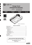
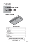
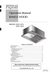
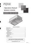
INSTALLATION MANUAL
WS06
www.fujioh.com
IMPORTANT
Top
Must use this wiring diagram for installation.
Do not use Thermador wiring diagram.
WARNING
Electrical wiring should be done by a qualified person(s)
in accordance with all applicable codes and standards,
including fire-rated construction. An unqualified person
doing the work could result in fire, electric shock or injury.
This switch uses 120 V AC, Max 16 Amp. Do not connect
to other voltage or over current rate since fire, electric
shock or damage could result.
GE Switch:
ASR-4173-500
(UL Recognized
Component)
Switch: Red
Low speed
LO
OFF
MED
Switch: Yellow
HI
Switch: Black
High speed
Switch: Blue
Medium speed
< CONNECTING POWER SUPPLY WIRES >
BLACK
/120V AC
1. A 2-1/2" deep Wall Box must be used to allow space for
wire connections between switch and 120 volt Power
Input Leads.
No Use
Blue
Red
Neutral
Ground
Black
Be sure to switch power OFF at service panel before
wiring.
WHITE
/NEUTRAL
2. Connect the electrical wires in accordance with
wiring diagram (figure 1).
Connect wires tightly and securely using wire
connectors (not supplied).
3. Attach the wall plate, and secure with 2 screws.
4. Turn on the electrical circuit to the power unit. Check
the ventilating functions at each speed control
positions. Make sure that the range hood has no
abnormal noises and/or vibration.
From
Blower Moter
FIG 1 < Connection Diagram >
Your installation is now complete.
If you should require service or replacement
parts on your ventilation system.
contact:
2-1/2" Deep Wall Box
(must be grounded)
Fuji Industrial USA,Inc.
16300 Christensen Rd, #212 Seattle, WA 98188
1-888-547-9880
Motor Green or
Bare Ground Wire
- Grounded to
Wall Box
Bowers #52 or Equivalent
FIG 2
READ AND SAVE THESE INSTRUCTIONS.
Keep this manual in a convenient place for future reference.
FUJI INDUSTRIAL CO.,LTD .
030984