1
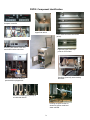
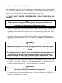
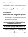
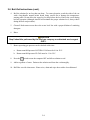
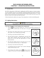
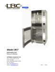
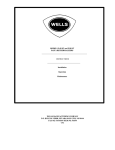
FGP55 Rethermalizer
Installation and Operation Manual
Non-CE &
Frymaster, a member of the Commercial Food Equipment Service Association, recommends
using CFESA Certified Technicians.
24-Hour Service Hotline 1800-551-8633
OCTOBER 2006
*8195845*
Please read all sections of this manual and retain for future reference.
NOTICE
This appliance is intended for professional use only and is to be operated by qualified
personnel only. A Frymaster Dean Factory Authorized Service Center (FASC) or other
qualified professional should perform installation, maintenance, and repairs. Installation,
maintenance, or repairs by unqualified personnel may void the manufacturer’s warranty.
NOTICE
This equipment must be installed in accordance with the appropriate national and local
codes of the country and/or region in which the appliance is installed.
NOTICE
This equipment is to be installed in compliance with the basic plumbing code of the Building
Officials and Code Administrators International, Inc. (BOCA) and the Food Service Sanitation
Manual of the U.S. Food and Drug Administration.
NOTICE
Drawings and photos used in this manual are intended to illustrate operational, cleaning and
technical procedures and may not conform to onsite management operational procedures.
DANGER
Improper installation, adjustment, maintenance or service, and unauthorized alterations or
modifications can cause property damage, injury, or death. Read the installation, operating
and service instructions thoroughly before installing or servicing this equipment. Only
qualified service personnel may convert this appliance to use a gas other than that for which
it was originally configured.
DANGER
Adequate means must be provided to limit the movement of this appliance without
depending upon the gas line connection. Single fryers equipped with legs must be
stabilized by installing anchor straps. All fryers equipped with casters must be stabilized by
installing restraining chains. If a flexible gas line is used, an additional restraining cable
must be connected at all times when the fryer is in use.
NOTICE
The Commonwealth of Massachusetts requires any and all gas products to be installed by a
licensed plumber or pipe fitter.
i
DANGER
The front ledge of the fryer is not a step. Do not stand on the fryer. Serious injury can result
from slips or contact with the hot oil.
CAUTION
Do not store or use gasoline or other flammable vapors and liquids in the vicinity of this or
any other appliance.
CAUTION
Instructions to be followed in the event the operator smells gas or otherwise detects a gas
leak must be posted in a prominent location. This information can be obtained from the
local gas company or gas supplier.
WARNING
No structural material on the fryer should be altered or removed to accommodate placement
of the rethermalizer under a hood. Questions? Call the Frymaster Dean Service Hotline at
1-800-551-8633.
WARNING
Do not bang fry baskets or other utensils on the fryer’s joiner strip. The strip is present to
seal the joint between the frypot. Banging fry baskets on the strip to dislodge shortening
will distort the strip, adversely affecting its fit. It is designed for a tight fit and should only
be removed for cleaning.
NOTICE TO OWNERS OF UNITS EQUIPPED WITH COMPUTERS
U.S.
This device complies with Part 15 of the FCC rules. Operation is subject to the following two
conditions: 1) This device may not cause harmful interference, and 2) This device must
accept any interference received, including interference that may cause undesired operation.
While this device is a verified Class A device, it has been shown to meet Class B limits.
CANADA
This digital apparatus does not exceed the Class A or B limits for radio noise emissions as
set out by the ICES-003 standard of the Canadian Department of Communications.
Cet appareil numerique n’emet pas de bruits radioelectriques depassany les limites de
classe A et B prescrites dans la norme NMB-003 edictee par le Ministre des Communications
du Canada.
ii
FGP55 SERIES RETHERMALIZER
INSTALLATION AND OPERATION MANUAL
TABLE OF CONTENTS
Page #
1.
2.
3.
INTRODUCTION
1-1
1.1
FGP55 Series Rethermalizer
1-1
1.2
Safety Information
1-1
1.3
Computer Information
1-2
1.4
Shipping Damage Claim Procedure
1-2
1.5
Maintenance/Repair Information
1-2
INSTALLATION INSTRUCTIONS
2-1
2.1
General
2-1
2.2
Service Personnel
2-2
2.3
Installation Instructions
2-2
2.4
Pre-Connection Preparations
2-4
2.5
Converting to Another Type of Gas
2-7
2.6
Boil-Out Instructions
2-7
OPERATING INSTRUCTIONS
3-1
3.1
Introduction
3-1
3.2
Lighting Instructions
3-1
3.3
Daily Checks and Services
3-2
3.4
Quarterly Checks and Services
3-3
3.5
Computer Operation
3-4
3.6
Programming the FGP55 CM-III.5 Computer
3-5
3.7
Operating the FGP55 Rethermalizer
3-7
3.8
Temperature Display Options
3-8
3.9
Computer Display Messages
3-8
3.10 Boil and Simmer Mode Options
3-9
3.11 Clock Speed Options
3-9
iii
FGP55 Component Identification
Computer controller
Upper float switch.
Cook vessel and lower float switch
(arrow).
Control box
Water by-pass switch, fuses and
reset button under control box.
High-limit (upper) and temp
probe in cook vessel.
FGP 55
Gas fitting (from left), water hookup
and drain.
Gas valve and drain handle on
spark-module equipped unit.
Position of standing pilot (arrow) on
unit with that feature.
Housing for spark module on
electronic ignition model and
water solenoid.
iv
FGP55 Rethermalizer Sequence of Operation
1. Ensure the unit is properly installed. Check the
following:
a. Rethermalizer is level under the vent
hood.
b. Gas supply is connected properly with the
proper gas type (natural or propane) with
the correct size lines. Have the installer
check for proper gas pressure and for gas
leaks.
c. Water connected properly to the coupling
at the rear of the unit.
d. Ensure drain plumbing is routed to the
disposal area.
e. Perform boil-out before first use and
periodically thereafter.
Refer to Chapter 2,
Installation, page 2-1 —
2.8.
2. Ensure the product basket is properly placed in the heating vessel.
3. Perform Lighting Instructions.
Refer to Lighting
Instructions, pages 3-1 — 3-2.
4. Ensure drain valve is closed. Turn the computer
on by pressing the
switch. Note: A decimal
between digits 1 and 2 in either LED display
indicates that the burners are lit.
Refer to Chapter 3,
Operating Instructions,
page 3-4 — 3.9 for specific
product settings and
desired temperatures.
5. Monitor operation of unit as the water reaches
temperature. The computer will display
as water temperature nears programmed setpoint.
6. When the water reaches the desired temperature, place product in the slotted
product basket.
7. Remove product from the basket after the specified time.
v
FGP55 SERIES RETHERMALIZERS
CHAPTER 1: INTRODUCTION
1.1 FGP55 Series Rethermalizer
The Frymaster FGP55 is a hot water bath unit designed to rethermalize or reconstitute both
refrigerated and frozen vacuum-bagged food products. The FGP55 is manufactured to operate on
the type gas specified by the user, i.e., natural or propane gas. The instructions contained in this
manual should be read thoroughly before attempting to operate this equipment.
1.2 Safety Information
Before attempting to operate your unit, read the instructions in this manual thoroughly.
Throughout this manual, you will find notations enclosed in double-bordered boxes similar to the
ones below.
CAUTION boxes contain information about actions or conditions that may cause or result in a
malfunction of your system.
CAUTION
Example of a CAUTION box.
WARNING boxes contain information about actions or conditions that may cause or result in
damage to your system, and which may cause your system to malfunction.
WARNING
Example of a WARNING box.
DANGER boxes contain information about actions or conditions that may cause or result in injury
to personnel, and which may cause damage to your system and/or cause your system to malfunction.
DANGER
Hot water causes severe burns. Never attempt to move a rethermalizer containing
hot water or to transfer hot water from one container to another.
Rethermalizers in this series are equipped with automatic safety features:
1. Two high-temperature detection features shut off power to the burners should the temperature
controls fail.
2. One low-water detection feature shuts off power to the burner should the water level drop below
a safe level.
1-1
1.3 Computer Information
This equipment has been tested and found to comply with the limits for a Class A digital device,
pursuant to Part 15 of the FCC rules. While this device is a verified Class A device, it has been
shown to meet the Class B limits. These limits are designed to provide reasonable protection against
harmful interference when the equipment is operated in a commercial environment. This equipment
generates, uses and can radiate radio frequency energy and, if not installed and used in accordance
with the instruction manual, may cause harmful interference to radio communications. Operation of
the equipment in a residential area is likely to cause harmful interference in which case the user will
be required to correct the interference at their own expense.
The user is cautioned that any changes or modifications not expressly approved by the party
responsible for compliance could void the user's authority to operate the equipment.
If necessary, the user should consult the dealer or an experienced radio and television technician for
additional suggestions.
The user may find the following booklet prepared by the Federal Communications Commission
helpful: "How to Identify and Resolve Radio-TV Interference Problems". This booklet is available
from the U.S. Government Printing Office, Washington, DC 20402, Stock No. 004-000-00345-4.
1.4 Shipping Damage Claim Procedure
What to do if your equipment arrives damaged:
Please note that this equipment was carefully inspected and packed by skilled personnel before
leaving the factory. The freight company assumes full responsibility for safe delivery upon
acceptance of the equipment.
1. File Claim for Damages Immediately—Regardless of extent of damage.
2. Visible Loss or Damage—Be sure this is noted on the freight bill or express receipt and is signed
by the person making the delivery.
3. Concealed Loss or Damage—If damage is unnoticed until equipment is unpacked, notify the
freight company or carrier immediately and file a concealed damage claim. This should be done
within 15 days of date of delivery. Be sure to retain container for inspection.
1.5 Maintenance/Repair Information
Place parts orders directly with your local Frymaster Parts Distributor. A list of parts distributors was
included with the rethermalizer when shipped from the factory. If you do not have access to this list,
please contact the Frymaster Service Department at 1-800-551-8633 or 1-318-865-1711.
1-2
1.5 Maintenance/Repair Information (cont.)
For non-routine maintenance or repairs, or for service information, contact your local Frymaster
Authorized Service Center (FASC). Service information may also be obtained by calling the
Frymaster Technical Services Department (1-800-551-8633). The following information will be
needed in order to assist you efficiently:
Model Number ______________________________
Serial Number ______________________________
Gas Type __________________________________
Nature of the Problem ________________________
__________________________________________
__________________________________________
RETAIN AND STORE THIS MANUAL IN A SAFE PLACE FOR FUTURE USE.
1-3
FGP55 SERIES RETHERMALIZERS
CHAPTER 2: INSTALLATION
2.1
General
Proper installation is essential for the safe, efficient, trouble-free operation of this appliance.
Any unauthorized alteration or improper installation of this equipment will void the
Frymaster warranty.
DANGER
The electrical power supply for this appliance MUST be the same as indicated on
the rating and serial number plate located on the inside of the fryer door.
DANGER
This appliance MUST be connected to the voltage and phase as specified on the
rating and serial number plate located on the inside of the fryer door.
DANGER
Do not store or use gasoline or other flammable vapors and liquids in the vicinity of
this or any other appliance.
All installation and service on Frymaster equipment must be performed by qualified, certified,
licensed, and/or authorized installation or service personnel.
Service may be obtained by contacting your local Factory Authorized Service Center.
In the event of a power failure, the rethermalizer will automatically shut down. Do not attempt to
start the rethermalizer until power is restored.
This appliance must be kept free and clear of combustible material, except that it may be installed on
combustible floors.
A clearance of 6 inches (15cm) must be provided at both sides and back adjacent to combustible
construction. A minimum of 24 inches (61cm) should be provided at the front of the equipment for
servicing and proper operation.
WARNING
Do not block the area around the base or under the rethermalizer.
2-1
2.2 Service Personnel
2.2.1 Definitions
A. Qualified and/or Authorized Operating Personnel
1. Qualified or authorized operating personnel are those who have carefully read the
information in this manual and have familiarized themselves with the equipment
functions, or have had previous experience with the operation of equipment covered in
this manual.
B. Qualified Installation Personnel
1. Qualified installation personnel are: individuals, firms, corporations and/or companies
which, either in person or through a representative, are engaged in and are responsible
for the installation of gas-fired appliances. Qualified installation personnel must be
experienced in such work, be familiar with all gas precautions required, and have
complied with all requirements of state and local codes.
C. Qualified Service Personnel
1. Qualified service personnel are those familiar with Frymaster equipment and have been
authorized by Frymaster Dean. All authorized service personnel are required to be
equipped with a complete set of service parts manuals and stock a minimum amount of
parts for Frymaster equipment.
2. A list of Factory Authorized Service Centers was included with the unit when shipped
from the factory. If you do not have access to this list, please contact Frymaster Dean
Customer Service using the number listed on the front of this manual. Failure to use
qualified service personnel will void the warranty.
2.3
Installation Instructions
2.3.1 General Installation Requirements
PROPER INSTALLATION IS ESSENTIAL FOR EFFICIENT, TROUBLE-FREE
OPERATION OF YOUR RETHERMALIZER. ANY UNAUTHORIZED ALTERATIONS
MADE TO THIS EQUIPMENT WILL VOID THE FRYMASTER WARRANTY.
Upon arrival, inspect the rethermalizer carefully for visible or concealed damage. (See Shipping
Damage Claim Procedure in Chapter 1.)
CLEARANCE AND VENTILATION
This equipment must be installed with a 6” (150mm) clearance at both sides and back when installed
adjacent to combustible construction. No clearance is required when installed adjacent to
noncombustible construction. A minimum of 24” (600mm) clearance should be provided at the
front of the unit.
2-2
2.3.1 General Installation Requirements (cont.)
One of the most important considerations of efficient operation is ventilation. Make sure the
equipment is installed so that products of combustion are removed efficiently, and that the kitchen
ventilation system does not produce drafts that interfere with proper burner operation.
The equipment flue opening must not be placed close to the intake of the exhaust fan, and the flue
must never be extended in a “chimney” fashion. An extended flue will change the combustion
characteristics of the equipment, causing longer recovery times. It also frequently causes delayed
ignition. To provide the airflow necessary for good combustion and burner operation, the areas
surrounding the front, sides, and rear of the unit must be kept clear and unobstructed.
This equipment must be installed in an area with an adequate air supply and adequate ventilation.
For U.S installations, information on construction and installation of ventilating hoods can be found
in NFPA Standard 96. This document can be ordered from the National Fire Protection Association,
Battery March Park, Quincy, MA 02269. For installations in countries other than the U.S., the
appropriate regulating authority should be contacted for information related to hood construction and
installation.
DANGER
Do not attach an apron drain to a single rethermalizer. The rethermalizer may
become unstable, tip over, and cause injury to personnel.
NATIONAL CODE REQUIREMENTS
This equipment is to be installed in compliance with the Basic Plumbing Code of the Building
Officials and Code Administrators International, Inc. (BOCA) and the Food Service Sanitation
Manual of the U.S. Food and Drug Administration.
This equipment is manufactured to use the type of gas specified on the rating plate attached to the
door. Connect equipment stamped “NAT” only to natural gas and that stamped “PRO” only to LP
(Propane) gas.
Installation shall be made with a gas connector that complies with national and local codes. Quick
disconnect devices, if used, shall likewise comply with national and local codes.
ELECTRICAL GROUNDING REQUIREMENTS
All electrically operated appliances must be grounded in accordance with all applicable national and
local codes. A wiring diagram is located on the inside of the door. In the United States and Canada,
the electrical supply must be 120VAC, 60 Hz. In other countries, refer to the rating plate on the
inside of the door for proper voltages.
2-3
2.3.1 General Installation Requirements (cont.)
FCC COMPLIANCE
The user is cautioned that any changes or modifications to Frymaster computers not expressly
approved by the party responsible for compliance could void the user’s authority to operate the
equipment. Frymaster computers have been tested and found to comply with the limits for a Class A
digital device, pursuant to Part 15 of the FCC rules. While these devices are verified as Class A
devices, they have been shown to meet the Class B limits. These limits are designed to provide
reasonable protection against harmful interference when the equipment is operated in a commercial
environment. This equipment generates, uses, and can radiate radio frequency energy and, if not
installed and used in accordance with the instruction manual, may cause harmful interference to
radio communications. Operation of the equipment in a residential area is likely to cause harmful
interference in which case the user will be required to correct the interference at his own expense. If
necessary, the user should consult the dealer or an experienced radio and television technician for
additional suggestions.
The user may find the booklet “How to Identify and Resolve Radio-TV Interference Problems”
helpful. It is prepared by the Federal Communications Commission and is available from the U.S.
Government Printing Office, Washington, DC 20402, Stock No. 004-000-00345-4.
2.3.2 Caster/Leg Installation
Depending upon the specific configuration ordered, your unit may have been shipped without
installed casters or legs. If casters or legs are installed, you may skip this section and proceed to
Section 2.4, Pre-Connection Preparations.
If your unit requires the installation of casters/legs, install them in accordance with the
instructions included in your accessory package.
2.4
Pre-Connection Preparations
DANGER
Do not connect this equipment to the gas supply before completing each step in this
section.
After the unit is positioned for use, ensure the following have been accomplished before connecting
the unit to the gas supply:
1.
Adequate means must be provided to limit the movement of this equipment without depending
upon the gas line connections. If a flexible gas hose is used, a restraining cable must be
connected at all times when the equipment is in use.
2.
The rethermalizer must be stabilized by installing restraining chains on units equipped with
casters or anchor straps on units equipped with legs. Follow the instructions shipped with the
casters/legs to properly install the chains or straps.
3.
Level rethermalizers equipped with legs by screwing out the legs approximately 1 inch then
adjusting them so that the rethermalizer is level.
2-4
2.4
4.
Pre-Connection Preparations (cont.)
For rethermalizers equipped with casters, there are no built-in leveling devices. The floor where
the rethermalizer is to be installed must be level.
WARNING
Inlet water pressure must not exceed 80 PSI. A regulator must be installed between
rethermalizer water inlet and water supply when pressure exceeds 80 PSI.
5.
Connect the water hose to the fitting at the rear of the unit. If inlet water pressure exceeds 80
PSI, a regulator must be installed to prevent damage to rethermalizer. Ensure that water
pressure to rethermalizer is less than 80 PSI.
NOTE 1: The unit may be equipped with an optional hose assembly with a quick-disconnect
coupling or hose provided by others. Whichever is used, it should be attached to a COLD
WATER SERVICE ONLY. Teflon thread-seal tape or Loctite PST56765 or equivalent
thread sealer must be used when installing the fittings.
4. Connect the desired drain plumbing to the 1¼" drain valve.
5. Test the equipment’s electrical system by plugging the power cord into a grounded 120VAC
outlet and pressing the computer’s ON/OFF button. °or
should appear in the
display.
6. Turn the computer off. Verify that the display is blank.
7. Verify that the minimum and maximum incoming gas pressures for the type of gas to be used are
in accordance with the accompanying table.
Incoming Gas Pressures
Gas
Natural
LP
Minimum
6" W.C.
1.49 kPa
14.93 mbar
Maximum
14" W.C.
3.48 kPa
34.84 mbar
11" W.C.
2.74 kPa
27.37 mbar
14" W.C.
3.48 kPa
34.84 mbar
2.4.1 Connecting to the Gas Supply
GAS CONNECTIONS AND PIPE SIZES
The size of the gas supply pipe is very important. If the pipe is too small, the gas pressure at the
burner manifold will be low. This will cause slow recovery and delayed ignition. The incoming gas
supply line should be a minimum of 1½ inches (38mm) ID.
2-5
2.4.1 Connecting to the Gas Supply (cont.)
When configured for natural gas, this equipment requires a standard gas pipe size of ¾ inch (22 mm)
ID for connections within 20 feet (6 m) of the supply line, provided no more than 4 fittings or
elbows are used in the run. For a pipe run over 20 feet (6 m), increase the pipe size to 1 inch (28
mm). For use with LP (Propane) gas, the next smaller pipe size may be used.
IF IN DOUBT ABOUT THE PIPE SIZE TO BE USED, CONSULT YOUR LOCAL GAS
COMPANY.
DANGER
Before connecting new pipe to this equipment, the pipe must be blown out
thoroughly to remove all foreign material. Foreign material in the burner and gas
controls may cause improper and dangerous operation.
1. Connect the equipment to the gas supply line. When making connections, apply a small amount
of Loctitite® PST 56765 or equivalent thread compound to the male threads only. DO NOT
apply the compound to the first two threads. This will prevent clogging of the burner orifices
and control valve.
2. Open the gas supply to the fryer and check all piping, fittings, and gas connections for leaks. A
soap-and-water solution should be used for this purpose. NEVER USE OPEN FLAME TO
CHECK FOR GAS LEAKS.
DANGER
Never use matches, candles, or any other ignition source to check for leaks.
If gas odors are detected, shut off the gas supply to the fryer at the main shut-off
valve and contact the local gas company or an authorized service agency for
service.
The rethermalizer and any shut-off valves installed between the rethermalizer and
the gas supply line must be disconnected from the gas supply line during any
pressure testing of the supply line at pressures equal to or greater than ½ PSIG
(3.45kPa, 14 inches W.C.).
3. Close the drain valve and fill the cookpot with water and boil-out solution to the overflow. Light
the burners as described in Chapter 3, “Operating Instructions”, and perform the boil-out
procedures as described in section 2.6, “Boil-Out Instructions” of this manual.
WARNING
"Dry-firing" this equipment will cause damage to the cookpot. Always ensure that
the cookpot is filled with water before firing your unit.
4. It is suggested that the burner manifold pressure be checked at this time by the local gas
company or an authorized service agent.
2-6
2.5 Converting to Another Gas Type
This equipment is configured at the factory for either natural gas or LP (propane) gas.
If you desire to switch from one type of gas to the other, a gas conversion kit must be installed by a
Factory Authorized Service Center technician.
DANGER
Switching to a different type of gas without installing the proper conversion kit may
result in fire or explosion! NEVER attach your fryer to a gas supply for which it is
not configured.
2.6 Boil-Out Instructions
CAUTION
Do not leave rethermalizer unattended. The boil-out solution may foam and overflow
if rethermalizer is left unattended. Press the
switch to turn computer OFF to
control this condition.
1.
Before turning the computer ON, close the drain valve and fill empty vessel with a mixture
of cold water to the overflow tube (use auto-fill by-pass switch as needed). Add a
commercial grade detergent formulated to effectively clean and sanitize food-contact
surfaces. Follow instructions on container when mixing.
CAUTION
Use a commercial grade cleaner formulated to effectively clean and sanitize foodcontact surfaces. Read directions for use and precautionary statements of cleaner.
Particular attention should be paid to the concentration of cleaner and the length of
time the cleaner rests on the food-contact surfaces.
WARNING
If gas odors are detected, the appliance gas supply MUST be shut off at the main
shut-off valve, and the local gas company or authorized service agency contacted
for service.
2.
switch to turn the
Follow LIGHTING INSTRUCTIONS in Section 3.2. Press the
computer on. An illuminated dot between digits 1 and 2 in either LED display indicates
that the burners are lit. (AutoFill will add water if the boil-out solution level is inadequate.)
3.
The Boil Mode is selected by pressing the
(L) button. The computer will display
and the temperature of the vessel will be raised to 212°F (100°C).
2-7
2.6 Boil-Out Instructions (cont.)
4.
Boil the solution for no less than one hour. To remove deposits, scrub the sides of the vat
with a long-handle, natural bristle brush, being careful not to damage the temperaturesensing probe. Do not allow the water level to drop below the level line in the vessel during
boil-out operation (although AutoFill will maintain the proper solution level, always check
during the boil-out procedure).
5.
Clean all food-contact areas above the water level line with a proper dilution of sanitizing
detergent.
6.
Rinse.
CAUTION
Step 8 should be performed by the local gas company or authorized service agent
ONLY.
7.
Burner operating gas pressure can be checked at this time.
a.
Burner manifold pressure NATURAL GAS must be 4.0 in. W.C.
b.
Burner manifold pressure LP GAS must be 11 in. W.C.
8.
Press the
switch to turn the computer OFF and allow solution to cool.
9.
Add two gallons of water. Drain out the solution and clean the vat thoroughly.
10. Refill the vat with clean water. Rinse twice, drain and wipe down with a clean dishtowel.
2-8
FGP55 SERIES RETHERMALIZERS
CHAPTER 3: OPERATING INSTRUCTIONS
3.1 Introduction
The FGP55 rethermalizer is offered with a standing pilot with Piezo ignitor or electronic ignition.
The unit is equipped with a low-level float switch, which allows ignition of the burners only after the
proper water level is reached. An auto-refill float switch maintains the normal water level. A water
by-pass switch, located below the control panel (see Page iv), can be used to raise the water level for
boil-out or in the case of a failure in the auto-refill mode.
Cold food should not be added to the cookpot, if the rethermalizer is in the hot-food holding mode.
3.2 Lighting Instructions
CAUTION
Vessel MUST be filled with water before lighting.
Follow these instructions for units equipped with a standing pilot:
1. Press the
switch to turn the computer ON. If the vessel is not filled to the proper level
with water, the AutoFill feature will add water to the proper
level.
6.
Turn the gas valve knob to the ON position.
7.
An illuminated dot between digits 1 and 2 in either LED display
indicates that the burners are lit.
OF
F
The pilot flame should remain lit. If the pilot goes out, wait at
least 5 minutes, then follow Step 4 to re-light the pilot.
P
5.
OT
Push and hold the knob in. Simultaneously, press the Piezo
ignitor button repeatedly until the pilot lights. Continue to
depress the gas valve pilot knob approximately 60 seconds.
Release the knob.
P I L OT
4.
If the burners fail to light, press the
switch to turn the
computer OFF and wait 60 seconds. Repeat the preceding steps.
3-1
OFF
8.
P
Turn the gas valve knob to the PILOT position.
ON
3.
OFF
IL
Turn the gas valve knob (open the door to gain access) to the
OFF position. Wait 5 minutes before proceeding.
ON
2.
IL
OT
ON
3.2 Lighting Instructions (cont.)
Follow these instructions to light a unit with electronic ignition:
1. Turn the gas valve knob to the ON position.
OFF
2. Press the
switch to turn the computer ON. If the vessel is not
filled to the proper level with water, the AutoFill feature will add
water to the proper level.
ON
3. An illuminated dot between digits 1 and 2 in either LED display
indicates that the burners are lit.
4. If the burners fail to light, press the
Repeat the preceding steps.
switch to turn the computer OFF and wait 60 seconds.
3.3 Daily Checks and Services
INSPECT RETHERMALIZER AND ACCESSORIES FOR DAMAGE
Look for loose or frayed wires and cords, leaks, foreign material in cookpot or inside cabinet, and
any other indications that the rethermalizer and accessories are not ready and safe for operation.
CLEAN CABINET INSIDE AND OUT
Clean inside the cabinet with a dry, clean cloth. Wipe all accessible metal surfaces and components
to remove accumulations of oil, dust, or cooking residue.
Clean the outside of the cabinet with a clean cloth dampened with dishwashing detergent, removing
oil, dust, or cooking residue.
DANGER
Never attempt to clean rethermalizer during the rethermalizing process or when the
cookpot is filled with hot water and/or food products.
Clean Float Levels, Temperature Probe, and Cookpot
Press the computer power switch to the OFF position.
Remove the shield that protects the upper float switch by
lifting up. Clean the exposed shaft with a solution of
detergent and water. A Scotchbrite™ or equivalent nylon
pad may be used to scrub away any accumulated mineral
deposits. Care must be taken not to bend or dislodge the
shaft or to impede the motion of the float. Use the same
cleaning procedure to clean the lower float switch.
3-2
Figure 1: The float switches (above and right)
should be cleaned periodically to eliminate
starch buildup, which can impede the motion of
the floats. Care must be taken, however, to
ensure the shafts are not dislocated or the
movement of the float hindered.
3.3
Daily Checks and Services (cont.)
Clean the temperature probe and high-limit, located on the burner tube in the cook vessel. Using a
Scotchbrite™ or similar mildly abrasive pad and a solution of detergent and water, clean the inside
of the cookpot.
Clean all food-contact surfaces with a proper dilution of a sanitizing detergent.
Rinse the cookpot thoroughly with clean water at least twice.
3.4
Quarterly Checks and Services
Check Computer Magic III.5 Setpoint Accuracy
1. Fill the cookpot with water. Press the computer power switch, and then press any of the product
buttons. Insert a good-grade thermometer or pyrometer probe into the cookpot, with the end
touching the temperature probe.
When the computer display shows a series of four dashes (
), press the
switch once to
display the temperature of the water as sensed by the temperature probe. Press the
switch twice
to display the setpoint. The displayed water temperature should be within ±10°F (5°C) of the
setpoint. The temperature shown on the thermometer or pyrometer should be within ± 5ºF (2ºC) of
the displayed water temperature. If either set of readings is outside its range, contact a Factory
Authorized Service Center for assistance.
3-3
3.5 Computer Operation
ITEM
1
DESCRIPTION
Lighted Displays— display of various functions and operations.
2
Power Switches— either switch turns power ON or OFF
3
Program Lock and Temperature Check Switch— locks program in
computer and/or displays vessel temperature when depressed.
4
Programming Switch— used when reprogramming the computer
memory.
5
Boil Mode Switch— overrides programmed setpoint and raises/
maintains temperature at 212°F (100°C)
6/7
Product and Coding Switches -- provides access to computer and
programming functions.
8
Simmer Mode Switch— maintains programmed setpoint temperature.
WARNING
Before turning on computer, ensure the rethermalizer is filled with water.
3–4
3.5 Computer Operation (cont.)
The FGP55 CM-III.5 computer has 10 programmable product buttons, a Simmer Mode switch, and a
Boil Mode switch. The computer also has two Power switches. Either switch may be pressed to
turn the unit ON or OFF.
The product buttons are multi-functional. In the programming mode, each button can be
programmed for a distinct rethermalizing time for a particular product. In the rethermalizing mode,
pressing a button initiates a timed countdown of the specific product associated with the button.
When the
switch is pressed, the programmed setpoint is overridden and the vessel temperature is
raised to and maintained at 212°F (100°C). When the unit is in boil mode,
appears in both
LED displays. The unit will remain in the boil mode until the Simmer Mode switch is pressed or the
unit is turned off.
The Simmer Mode is activated by pressing the
(R) switch. In Simmer Mode, the vessel
temperature is maintained at the programmed setpoint. When the switch is pressed, if the vessel
temperature is above the setpoint, °is displayed in both LED widows. If the vessel
temperature is below the setpoint, °is displayed. If the temperature is within 11°F (6°C) of the
setpoint,
(four dashes) is displayed.
3.6 Programming the FGP55 CM-III.5 Computer
CAUTION
It is recommended that the simmer setpoint and the heat/stir times for all 10
products be programmed before the unit is first used in a rethermalizing cycle.
When the unit is tested at the factory, the simmer setpoint and product rethermalizing times are
programmed. These test settings are not default settings. You must program the unit for your own
particular products. Program the setpoint and all product rethermalizing times as follows:
1. Turn the computer on by pressing the
switch.
2. Enter the programming mode by pressing the
switch.
appears in the left display. If
you enter the programming mode by mistake, press the switch again to exit the programming
mode
NOTE 1: If you try to enter the programming mode while the computer is rethermalizing, the
display will flash
.
3–5
3.6 Programming the FGP55 CM-III.5 Computer (cont.)
NOTE 2: The unit comes from the factory configured to display in degrees Fahrenheit. To
toggle back and forth between Fahrenheit and Celsius, press the
switch, then enter the code
1 6 5 8 by pressing the corresponding product buttons. Next, press the
switch to lock in
the new display option.
3. Enter the number 1 6 5 0 by pressing the corresponding product buttons. The computer
cannot be programmed unless this code is entered, thus preventing any unauthorized changes to
current program instructions.
4.
(Setpoint) will appear in the left LED display. Any previously programmed temperature
setpoint will appear in the right display. To change the setpoint, enter the desired setpoint
temperature using the corresponding product buttons. The setpoint can be programmed for any
value up to 212°F (100°C). Press the Program Mode
switch to lock in the new setpoint (or
the old setpoint, if it was not changed).
5.
(Select Product) will appear in the left display. Press the product button to be
programmed (or press
to return to the normal operating mode).
6.
(Rethermalizing Time) will now show in the left display. Any previously programmed
rethermalizing time will appear in the right display. Pressing
will accept the current
rethermalizing time. To change the rethermalizing time, enter the new time using the product
buttons. The rethermalizing time can be programmed up to 59:59. Press
to lock in the new
time.
NOTE: The computer can be programmed for either "standard" or "slow" clock. The standard
clock displays minutes and seconds, the slow clock displays hours and minutes. To toggle
switch, then enter the code 1 6 5 3 using the product buttons.
between times press the
switch to lock in the clock speed. To determine whether the clock speed is set to
Press the
standard or slow, initiate a rethermalizing cycle by pressing a product button. If the computer is
set to the standard clock, the time in the LED display will immediately begin to count down. If
countdown does not begin immediately, the computer is set to the slow clock.
7.
SH1 (Stir Time 1) appears in the left display. If your product requires stirring during the
rethermalizing process, set the number of seconds to heat before stirring using the product
buttons. If your product does not require stirring, enter "0". The number entered will appear in
the right display. The stir time can be programmed up to 59:59, but must not exceed the
product rethermalizing time. Press
to lock in the programmed time.
For example, entering "30" means the product needs to be stirred after it has been rethermalizing
for thirty seconds. At the end of thirty seconds, an alarm will sound and the product switch will
flash until cancelled by the operator pressing the product button.
3–6
3.6 Programming the FGP55 CM-III.5 Computer (cont.)
SH2 will appear. Program the length of the second stir time as above being sure that the time
entered is greater than that for stir time "1" or else is "0".
SH3 will appear. Program the length of the third stir time in the same manner as for stir times
"1" and "2", being sure that the time entered is greater than that for stir time "2" or else is "0".
CAUTION
Remember: Stir time "2" must be greater than stir time "1" (or else be "0"). Stir time
"3" must be greater than stir time "2" (or else be "0"). None of the stir times should
be greater than the rethermalizing time entered in Step 6. If a stir time exceeds the
rethermalizing time, the stir time will be ignored.
8.
(Select Product) will again appear in the left display. If more products are to be
programmed, return to Step 5 and follow all instructions to this point, repeating for each product.
9. When you complete your programming, lock in the whole program by pressing the
switch.
3.7 Operating the FGP55 Rethermalizer
Turn the computer on by pressing the
switch. Note: An illuminated dot between digits 1 and 2
in either LED display indicates that the burners are lit.
1.
One of the following will be displayed:
a. °b. °c.
: indicates the vessel temperature is 11ºF (6ºC) lower than the setpoint.
: indicates the vessel temperature is 11ºF (6ºC) higher than the setpoint.
(four dashes): indicates the vessel temperature is nearing setpoint.
d.
: indicates a heating problem.
e.
: indicates a problem with the computer temperature probe circuit.
2. Press a product button to initiate a rethermalizing cycle.
a. The previously programmed rethermalizing time will appear and the timer countdown will
begin.
b. If stir times are programmed, the operator will be notified of the need to stir the product “X”
seconds after the rethermalizing cycle has begun (X = amount of time programmed). An
alarm will sound, the display will read Stir, and the LED in the product button will blink.
3–7
3.7 Operating the FGP55 Rethermalizer (cont.)
If no stir times have been programmed, Stir will not appear during the rethermalizing
cycle. To cancel the alarm, press the indicated product button.
CAUTION
Pressing the product button twice while the alarm is active will cancel the
rethermalizing cycle as well as the alarm.
c. At the end of the rethermalizing cycle, an audible alarm will sound,
will be
displayed, and the associated product button will flash. To cancel the alarm, press the
flashing button.
3. To check the vessel temperature at any time, press the
press the switch twice.
switch once. To check the setpoint,
(four dashes) should
During idle periods when the rethermalizer is on, but not in use,
appear in both displays, indicating that the vessel is at setpoint. If not, check the actual temperature
and setpoint.
3.8 FGP55 Temperature Display Options
Note: To enter the programming mode, press the
1 6 5 0.
•
switch. When the display reads
, enter
To toggle constant temperature display on and off, enter 1 6 5 1, then press the
switch.
Note: When in constant temperature display mode, the countdown time will not be
displayed.
•
To toggle between Fahrenheit and Celsius temperature display, enter 1 6 5 8, then
switch.
press the
3.9 FGP55 Computer Display Messages
e
e
– Prompts you to select a product button for programming.
– Prompts you to enter a sequence of numbers to change certain functions of the
computer.
e °e °-
– Indicates that the water temperature is more than 11°F above setpoint.
– Indicates that the water temperature is more than 11°F below setpoint.
3–8
3.9 FGP55 Computer Display Messages (cont.)
e
(four dashes) – Indicates that the water temperature is within the proper
rethermalizing range (i.e., within ±11°F of setpoint).
e
– Indicates that there is a heating problem. Call your local Factory Authorized
Service Center or the 24-Hour Hotline (1-800-551-8633).
e
– Indicates that the rethermalizer has detected a problem in the temperature control
circuits. Call your local Factory Authorized Service Center or the 24-Hour Hotline (1-800551-8633).
3.10 FGP55 Boil or Simmer Mode Options
In the Simmer Mode, the vessel temperature is maintained at the setpoint programmed by the
operator. In the Boil Mode, the vessel temperature is raised to 212°F (100°C).
Select the Simmer Mode by pressing the
(R) button. If the temperature of the vessel is above the
setpoint, °will be displayed. If the temperature of the vessel is below the setpoint, °will
be displayed. If the temperature is within 11°F (6°C) of the setpoint,
(four dashes) will be
displayed.
The Boil Mode is selected by pressing the
(L) button. The computer will display
temperature of the vessel will be raised to 212°F (100°C).
and the
See Section 2.6 for detailed boil-out instructions.
3.11 FGP55 Clock Display Options
The computer can be programmed to display rethermalizing time in minutes and seconds, or in hours
and minutes, depending on the product being rethermalized.
To toggle between display options, press the
switch, enter 1 6 5 3, then press the
. To
determine which display is active, initiate a rethermalizing cycle by pressing a product button. If the
display is set to minutes and seconds, the time will immediately begin to count down. If it does not,
the display is set to hours and minutes.
3–9
THIS PAGE INTENTIONALLY LEFT BLANK
Frymaster, L.L.C., 8700 Line Avenue, PO Box 51000, Shreveport, Louisiana 71135-1000
Shipping Address: 8700 Line Avenue, Shreveport, Louisiana 71106
TEL 1-318-865-1711
PRINTED IN THE UNITED STATES
FAX (Parts) 1-318-219-7140
SERVICE HOTLINE
1-800-551-8633
FAX (Tech Support) 1-318-219-7135
819-5845
OCTOBER 2006