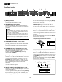
1
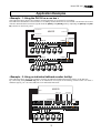
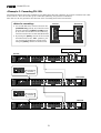
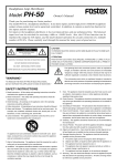
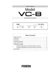
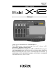
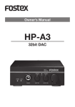
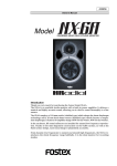
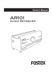
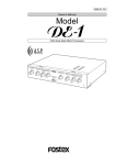
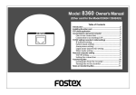
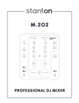
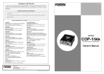
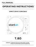
372228
Owner’s Manual
Model
PH-100
Headphone Amplifier / Distributor
5
1
2
3
5
4
5
5
5
6
5
7
5
8
5
9
5
10
5
5
5
AUX IN
PH-100
HEADPHONE AMP DISTRIBUTOR
0
10
0
10
0
10
0
10
0
10
0
10
0
10
0
10
0
10
0
0
10
PEAK
10
5
CAL
ST
PHONES
MONO
0
10
POWER
INPUT
Introduction
Thank you very much for purchasing the Fostex PH-100 headphone amplifier/distributor. The PH-100 can distribute the input signal accepted by any of three pairs of stereo
input connectors to 10 headphones whose level can be adjusted independently. It also
provides the 10-input, 10-output matrix box function which allows independent feed
for each headphone. The PH-100 is equipped with two stereo pairs of balanced inputs
(+4 dBu XLR-3-31 connectors and -10 dBV phone jacks), as well as a stereo pair of
unbalanced inputs ( -10 dBV RCA pin jacks). It also provides the AUX IN jacks which are
useful when using the PH-100 as a cue box.
In addition, you can cascade PH-100s, making more than 10 persons possible to monitor
the same stereo source.
Please read through this manual before using, and always keep it nearby.
<Contents>
Safety Instructions ....................................................................................................................2
Notes on Operation ...................................................................................................................3
Names and Functions
Front panel section ..............................................................................................................3
Rear panel section ............................................................................................................ ...4
Application Examples
Example - 1: Using the PH-100 as a cue box ...................................................................5
Example - 2: Using an individual talkback monitor facility .......................................5
Example - 3: Cascading PH-100 .......................................................................................6
Main Specification .....................................................................................................................7
Block diagram .......................................................................................................................7
Model PH-100
CAUTION:
CAUTION
TO PREVENT ELECTRIC SHOCK, MATCH WIDE BLADE OF
PLUG TO WIDE SLOT, FULLY INSERT.
RISK OF ELECTRIC SHOCK
DO NOT OPEN
ATTENTION:
POUR EVITER LES CHOCS ELECTRIQUES, INTRODUIRE
LA LAME LA PLUS LARGE DE LA FICHE DANS LA BORNE
CORRESPONDANTE DE LA PRISE ET POUSSER JUSQU'
AU FOND.
CAUTION: TO REDUCE THE RISK OF ELECTRIC SHOCK,
DO NOT REMOVE COVER (OR BACK).
NO USER - SERVICEABLE PARTS INSIDE.
REFER SERVICING TO QUALIFIED SERVICE PERSONNEL.
The lightning flash with arrowhead symbol, within an equilateral
triangle, is intended to alert the user to the presence of
uninsulated "dangerous voltage" within the product's enclosure
that may be of sufficient magnitude to constitute a risk of electric
shock to persons.
"WARNING"
The exclamation point within an equilateral triangle is intended
to alert the user to the presence of important operating and
maintenance (servicing) instructions in the literature
accompanying the appliance.
"TO REDUCE THE RISK OF FIRE OR ELECTRIC SHOCK,
DO NOT EXPOSE THIS APPLIANCE TO RAIN OR
MOISTURE."
SAFETY INSTRUCTIONS
10. Power Sources - The appliance should be connected to a power
supply only of the type described in the operating instructions or
as marked on the appliance.
11. Grounding or Polarization - The precautions that should be taken
so that the grounding or polarization means of an appliance is
not defeated.
12. Power Cord Protection - Power supply cords should be routed
so that they are not likely to be walked on or pinched by items
placed upon or against them, paying particular attention to cords
at plugs, convenience receptacles, and the point where they
exit from the appliance.
13. Cleaning - The appliance should be cleaned only as
recommended by the manufacturer.
14. Nonuse Periods - The power cord of the appliance should be
unplugged from the outlet when left unused for a long period of
time.
15. Object and Liquid Entry - Care should be taken so that objects
do not fall and liquids are not spilled into the enclosure through
openings.
16. Damage Requiring Service - The appliance should be serviced
by qualified service personnel when:
1. Read Instructions - All the safety and operating instructions
should be read before the appliance is operated.
2. Retain Instructions - The safety and operating instructions
should be retained for future reference.
3. Heed Warnings - All warnings on the appliance and in the
operating instructions should be adhered to.
4. Follow Instructions - All operating and use instructions should
be followed.
5. Water and Moisture - The appliance should not be used near
water - for example, near a bathtub, washbowl, kitchen sink,
laundry tub, in a wet basement, or near a swimming pool, and
the like.
6. Carts and Stands - The appliance should be used only with a
cart or stand that is recommended by the manufacturer.
An appliance and cart combination should be moved with care.
Quick stops, excessive force, and uneven surfaces may cause
the appliance and cart combination to overturn.
A.
B.
C.
D.
The power supply cord or the plug has been damaged; or
Objects have fallen, or liquid has been spilled into the appliance; or
The appliance has been exposed to rain; or
The appliance does not appear to operate normally or
exhibits a marked change in performance; or
E. The appliance has been dropped, or the enclosure damaged.
7. Wall or Ceiling Mounting - The appliance should be mounted to
a wall or ceiling only as recommended by the manufacturer.
8. Ventilation - The appliance should be situated so that its location
or position dose not interfere with its proper ventilation.
For example, the appliance should not be situated on a bed,
sofa, rug, or similar surface that may block the ventilation
openings; or, placed in a built-in installation, such as a bookcase
or cabinet that may impede the flow of air through the ventilation
openings.
9. Heat - The appliance should be situated away from heat sources
such as radiators, heat registers, stoves, or other appliances
(including amplifiers) that produce heat.
17. Servicing - The user should not attempt to service the appliance
beyond that described in the operating instructions.
All other servicing should be referred to qualified service
personnel.
18. The appliance should be situated away from drops of water or
spray of water.
19. Objects containing liquid such as vase must not be put on the
appliance.
20. The appliance is not completely isolated from the power supply
even if the power switch is at off position.
2
Model PH-100
Notes on Operation
• Retard the sound volume control when the headphone plug
is connected or disconnected from the jack.
• Do not use headphones for long hours at high sound levels.
If the headphones is used under such condition, it could
injure your hearing. Also, be careful not to rapidly raise
the output control when using the headphone. Please use
good sense to protect your hearing.
Always turn down the sound volume control before the
headphone is plugged or unplugged while the volume
control is set too high, it could create noise and have hurt
your ears.
• Switch off power when connecting external equipment to PH100.
• Turn down all sound volume controls before switch on power.
Always switch off power to the PH-100 when connecting
external equipment to it.
Be sure to fully turn off all sound volume controls when
switching on/off power to the PH-100.
Names and Functions
Front Panel section
5
1
2
1
3
5
4
5
5
5
2
6
5
7
5
8
5
9
5
10
5
3
5
5
AUX IN
PH-100
HEADPHONE AMP DISTRIBUTOR
0
10
0
10
0
10
0
10
0
10
0
10
0
10
0
10
0
10
0
0
10
PEAK
10
5
CAL
ST
MONO
PHONES
6
2. [PEAK] indicator
Represents overload of the input signal.
If the indicator frequently lights up, turn down the
[INPUT] and / or [AUX IN] level controls so that the
indicator does not light up.
3. [AUX IN] level control
Controls the input level of the [INPUT] jacks
(balanced or unbalanced) on the rear panel.
ST
MONO
<Note>
0
CAL
10
MONO
The input signal is fed to the [PHONES]
and [CASCADE OUT] jacks in mono (L+R).
Each headphone jack on the front panel take priority to the corresponding (same number's) headphone jack on the rear panel.
You cannot use both front and rear jacks with the
same number simultaneously. If you connect headphones to both front and rear jacks with the same
number, you can only use the headphones connected to the front jack.
5. [INPUT] level control
5
The input signal is fed to the [PHONES]
and [CASCADE OUT] jacks in stereo.
<Note>
The switch turns on or off the power. The indicator
lights up when the power is on.
When turn on or off the power, set the level
controls of the PH-100 and connected device(s) to
the minimum positions.
INPUT
ST
Connect headphones. There are also headphone
jacks on the rear panel so you can use whichever
you like.
4. [POWER] switch/indicator
10
4
7. [PHONES] jacks (1 through 10)
Adjusts the input level of a stereo signal from the
[AUX IN] jacks on the rear panel. The signal adjusted
by this control is mixed with the stereo signal from
the [INPUT] jacks which is level-controlled by the
[INPUT] level control, and fed to both the [PHONES]
and [CASCADE OUT] jacks.
0
5
Selects whether monitoring a signal from the
[INPUT] jacks (balanced or unbalanced) in stereo or
mono.
Each control adjusts the output level of the
corresponding [PHONES] jack (1 through 10) on the
front or rear panel.
PEAK
POWER
6. [INPUT (ST, MONO)] select switch
1. [PHONES] level controls [1 through 10]
5
10
INPUT
7
AUX IN
0
At the CAL position,
you can get the nominal input level (+4 dBu
or -10 dBV). CAL position shows the
nominal position."
3
Model PH-100
Rear Panel section
2
1
5
10
AC IN
4
9
3
8
4
3
2
7
1
6
PHONES (PRIORITY TO "FRONT PHONES" OUTPUT)
L
5
10
R
CASCADE
OUT (-10dBV)
4
9
3
8
5 6
2
1
L/MONO
7
L/MONO
+4dBu
+4dBu
-10dBV
7
6
R
AUX IN
(-10dBV)
CHANNEL IN (-10dBV)
XLR
2
3
1
HOT
COLD
GND
PHONE
T
R
S
-10dBV
R
INPUT
(-10dBV)
INPUT L
INPUT R
8
You can control the signal level using the [INPUT]
control on the front panel.
To cascade two PH-100s, connect between the
[CASCADE OUT] jacks of the first unit and the
unbalanced [INPUT] jacks of the second unit.
See page 6 for details about cascade connection.
1. [AC IN] connector
Connects the supplied power cord.
2. [PHONES] jacks (1 through 10)
Connect headphones. There are also headphone
jacks on the front panel so you can use whichever
you like.
7. [INPUT (+4dBu)] connector (L, R) (XLR-3-31 type: +4dBu)
<Note>
Connect to +4 dBu balanced output connectors of
an external device.
A stereo signal from these balanced connectors are
sent [PHONES] jacks (1 through 10) on front and
rear panel.
You can control the signal level using the [INPUT]
control on the front panel.
Each headphone jack on the front panel take priority to the corresponding (same number's) headphone jack on the rear panel.
You cannot use both front and rear jacks with the
same number simultaneously. If you connect headphones to both front and rear jacks with the same
number, you can only use the headphones connected
to the front jack.
The pin assignment of the XLR connector
3. [CASCADE OUT] jacks (L, R) (RCA: -10dBV)
To cascade two PH-100s, connect between the
cascade jacks of the first unit and the unbalanced
[INPUT] jacks of the second unit.
See page 6 for details about cascade connection.
1
2
1
2
3
GND
HOT
COLD
3
4. [CHANNEL IN] jacks (1 through 10) (RCA: -10dBV)
The signal from each input jack is directly sent to
the corresponding headphone output.
i.e. The signal from [CHANNEL IN 5] is directly
output from [PHONES 5].
8. [INPUT (-10dBV)] jacks (L, R) (PHONE: -10dBV)
Connect to -10 dBV balanced output connectors of
an external device.
A stereo signal from these balanced connectors are
sent [PHONES] jacks (1 through 10) on front and
rear panel.
You can control the signal levels using the [INPUT]
control on the front panel.
5. [AUX IN] jacks (L/MONO, R) (RCA: -10dBV)
Connect to -10 dBV unbalanced output connectors
of an external device.
A stereo signal from these input jacks is sent the
[PHONES] jacks (1 through 10) on front and rear
panel. If you connect a plug only to the L/MONO
jack, the same signal is sent to both L and R
channels.
You can control the signal level using the [AUX IN]
control on the front panel.
The pin assignment of the phone plug
Tip Ring
Sleeve
6. [INPUT (-10dBV)] jacks (L/MONO, R) (RCA: -10dBV)
Connect to -10 dBV unbalanced output connectors
of an external device.
A stereo signal from these jacks is sent the [PHONES]
jacks (1 through 10) on front and rear panel.
If you connect a plug only to the “L/MONO” jack,
the same signal is sent to both L and R channels.
Sleeve
Tip
Ring
4
GND
HOT
COLD
Model PH-100
Application Examples
<Example - 1: Using the PH-100 as a cue box >
The following figure shows the example of using PH-100s as cue boxes for recording.
Each PH-100 is installed in each booth of a recording studio. Musicians in each booth can monitor the sound
with the desired balance between signals from the [INPUT] and [AUX IN] jacks by adjusting the [INPUT] and [AUX
IN] controls on the front panel.
CUE OUT #1
MIXER
MON OUT
CUE OUT #2
INPUT
AUX IN
5
1
2
3
5
4
5
5
5
6
5
7
5
8
5
9
5
10
5
5
5
AUX IN
PH-100
HEADPHONE AMP DISTRIBUTOR
0
10
0
0
10
0
10
0
10
10
0
0
10
10
0
10
0
0
10
0
10
10
PEAK
5
CAL
ST
MONO
0
PHONES
10
INPUT
AUX IN
5
1
2
3
5
4
5
5
5
POWER
INPUT
6
5
7
5
8
5
9
5
10
5
5
5
AUX IN
PH-100
HEADPHONE AMP DISTRIBUTOR
0
10
0
0
10
0
10
0
10
10
0
0
10
10
0
10
0
0
10
0
10
10
PEAK
5
CAL
ST
MONO
PHONES
0
10
POWER
INPUT
<Example - 2: Using an individual talkback monitor facility>
The following figure shows the example of using an individual talkback monitor facility of the PH-100.
By connecting each [CHANNEL IN] jack to an individual cue output of the mixing console which can send a
talkback signal, you can send talkback to an individual musician.
MIXER
INPUT
MON OUT
CUE OUT
CHANNEL IN
AC IN
4
3
2
1
10
9
8
7
6
2
3
5
4
5
5
5
6
5
L
INPUT
5
4
10
R
9
CASCADE
OUT (-10dBV)
PHONES (PRIORITY TO "FRONT PHONES" OUTPUT)
5
1
5
7
5
3
2
1
L/MONO
8
7
6
R
AUX IN
(-10dBV)
8
9
5
10
5
HOT
COLD
GND
+4dBu
+4dBu
XLR
2
3
1
PHONE
T
R
S
-10dBV
-10dBV
CHANNEL IN (-10dBV)
5
L/MONO
R
INPUT
(-10dBV)
INPUT L
5
5
AUX IN
INPUT R
PH-100
HEADPHONE AMP DISTRIBUTOR
0
10
0
10
0
10
0
10
0
10
0
10
0
10
0
10
0
10
0
0
10
PEAK
10
5
CAL
ST
PHONES
5
MONO
0
10
INPUT
POWER
Model PH-100
<Example -3: Cascading PH-100>
The following figure shows the example of cascading three PH-100s, allowing 30 persons to monitor the same
stereo source. You can cascade up to 10 PH-100s (allowing 100 persons to monitor).
Note that we do not guarantee the function when cascading more than ten PH-100s.
<Notes for cascading>
First unit
• To cascade PH-100s, connect between the
[CASCADE OUT] jacks (L, R) of the first unit
and the unbalanced [INPUT (-10 dBV)] jacks
(L, R) of the second unit. In the same way,
connect between the second and third units.
• By setting the [INPUT] control of the second
and third units to the "CAL" position, you
can control all headphone output levels
using the [INPUT] control of the first unit.
Second unit
L
L/MONO
R
R
INPUT
(-10dBV)
CASCADE
OUT (-10dBV)
External device
First unit
5
10
AC IN
5
INPUT
ST
MONO
0
4
9
3
8
2
7
1
6
L
5
4
3
2
1
L/MONO
R
10
9
8
7
6
R
CASCADE
OUT (-10dBV)
PHONES (PRIORITY TO "FRONT PHONES" OUTPUT)
L/MONO
+4dBu
+4dBu
AUX IN
(-10dBV)
CHANNEL IN (-10dBV)
HOT
COLD
GND
XLR
2
3
1
PHONE
T
R
S
-10dBV
-10dBV
R
INPUT
(-10dBV)
INPUT L
INPUT R
CAL
Set the [INPUT]
control to the
"CAL" position.
10
Second unit
5
10
AC IN
5
INPUT
ST
MONO
0
4
9
3
8
2
7
1
6
L
R
5
10
4
9
CASCADE
OUT (-10dBV)
PHONES (PRIORITY TO "FRONT PHONES" OUTPUT)
3
2
1
L/MONO
8
7
6
R
L/MONO
+4dBu
+4dBu
AUX IN
(-10dBV)
CHANNEL IN (-10dBV)
HOT
COLD
GND
XLR
2
3
1
PHONE
T
R
S
-10dBV
-10dBV
R
INPUT
(-10dBV)
INPUT L
INPUT R
CAL
10
Set the [INPUT]
control to the
"CAL" position.
Third unit
5
10
AC IN
4
9
3
8
2
7
PHONES (PRIORITY TO "FRONT PHONES" OUTPUT)
1
6
L
R
5
4
3
2
1
L/MONO
10
9
8
7
6
R
CASCADE
OUT (-10dBV)
CHANNEL IN (-10dBV)
6
L/MONO
+4dBu
+4dBu
-10dBV
-10dBV
AUX IN
(-10dBV)
R
INPUT
(-10dBV)
INPUT L
HOT
COLD
GND
INPUT R
XLR
2
3
1
PHONE
T
R
S
Model PH-100
Main Specification
<OUTPUT>
<INPUT>
INPUT (L, R) (Balanced)
• Connector
• Standard input level
• Input Impedance
PHONES OUT (1~10)
Available on both the front and rear panels (the front
jacks take priority.)
: XLR-3-31 type (x 2)
: PHONE (x 2)
: +4dBu (XLR-3-31 type)
: -10dBV (PHONE)
: 10kΩ or more
INPUT (L/MONO, R) (Unbalanced)
• Connector
: RCA pin (x 2)
• Standard input level
: -10dBV
• Input Impedance
: 10kΩ or more
AUX IN (L/MONO, R) (Unbalanced)
• Connector
: RCA pin (x 2)
• Standard input level
: -10dBV
• Input Impedance
: 10kΩ or more
CHANNEL IN (1~10) (Unbalanced)
• Connector
: RCA pin (x 10)
• Standard input level
: -10dBV
• Input Impedance
: 10kΩ or more
• Connector
• Maximum Output level
• Load impedance
• Frequency Response
• Noise
• Distortion
: PHONE (x 20)
: 500mW
: 8 ~ 32Ω
: 30Hz ~ 20kHz +/-1dB
: -65dBV or less
: 0.3% or less
CASCADE OUT (L, R)
• Connector
• Output level
• Frequency Response
• Noise
• Distortion
: RCA pin (x 2)
: -10dBV
: 30Hz ~ 20kHz +/-1dB
: -80dBV or less
: 0.1% or less
<GENERAL>
• Dimensions
• Weight
• Power supply
: 482 (W) x 49 (H) x 267 (D)
: Approx. 4kg
: 120VAC 60Hz
: 230V ~ 50/60Hz
• Power consumption : Approx. 18W
* Specifications and appearance are subject to change without notice for product improvement.
Block diagram
PEAK
INPUT
OUTPUT LEVEL 1
FRONT
INPUT L
PHONES 1
ST/MONO
REAR
BALANCE IN
OUTPUT LEVEL 2
FRONT
PHONES 2
INPUT R
REAR
OUTPUT LEVEL 3
FRONT
L/MONO
UNBAL IN
R
PHONES 3
REAR
AUX IN
L/MONO
AUX IN
R
OUTPUT LEVEL 4
FRONT
PHONES 4
1
REAR
2
3
OUTPUT LEVEL 5
FRONT
PHONES 5
4
REAR
5
CHANNEL IN
6
OUTPUT LEVEL 6
7
FRONT
PHONES 6
8
REAR
9
10
OUTPUT LEVEL 7
FRONT
PHONES 7
REAR
OUTPUT LEVEL 8
FRONT
PHONES 8
REAR
OUTPUT LEVEL 9
FRONT
PHONES 9
REAR
OUTPUT LEVEL 10
FRONT
PHONES 10
REAR
L
CASCADE OUT
R
7
Declaration of EC Directive
This equipment is compatible with the EMC Directive (89/336/EEC) - Directive on approximation of member
nation's ordinance concerning the electromagnetic compatibility and with the Low Voltage Directive (73/23/EEC)
- Directive on approximation of member nation's ordinance concerning electric equipment designed to be used
within the specified voltage range.
The Affect of Immunity on This Equipment
The affect of the European Specification EN50082-1 (coexistence of electromagnetic waves - common
immunity specification) on this equipment are as shown below.
In the electrical fast transient/burst requirements, surge, conducted disturbances by radio-frequency fields, power
frequency magnetic field, radiate electromagnetic field requirements and static electricity discharging environment,
this could be affected by generation of noise in some cases.
FOSTEX DISTRIBUTORS LIST IN EUROPE
* Including non-EU countries (as of June, 2002)
<AUSTRIA>
<ITALY>
NAME: ATEC Audio-u. Videogeraete VertriebsgesmbH.
ADD: Im Winkel 5, A-2325 Velm, Austria
TEL: (+43) 2234-74004, FAX: (+43) 2234-74074
NAME: Proel S. p. A.
ADD: Zona Alla Ruenia, 37/43 64027 - Sant'Omero (Teramo),
Italy
TEL: (+39) 0861-81241, FAX: (+39) 0861-887862
<BELGIUM>
NAME: EML Sound Industries NV
ADD: Bijvennestraat 1A, B3500 Hasselt, Belgium
TEL: (+32) 11-232355, FAX: (+32) 11-232172
<DENMARK>
NAME: SC Sound ApS
ADD: Malervej 2, DK-2630 Taastrup, Denmark
TEL: (+45) 4399-8877, FAX: (+45) 4399-8077
<FINLAND>
NAME: Noretron Oy Audio
ADD: P. O. Box 22, FIN-02631 Espoo, Finland
TEL: (+358) 9-5259330, FAX: (+358) 9-52593352
<FRANCE>
NAME: Guillard Musiques
ADD: ZAC de Folliouses, B. P. 609, Les Echets, 01706 Miribel,
France
TEL: (+33) 472 26 27 00, FAX: (+33) 472 26 27 01
<GERMANY>
NAME: Studiosound & Music GmbH
ADD: Industriestrasse 20, D-35041 Marburg, F. R. Germany
TEL: (+49) 6421-92510, FAX: (+49) 6421-925119
<GREECE>
NAME: Bon Studio S. A.
ADD: 6 Zaimi Street, Exarchia, 106.83 Athens, Greece
TEL: (+30) 1-3809605-8, 3302059, FAX: (+30) 1-3845755
<ICELAND>
NAME: I. D. elrf. electronic Ltd.
ADD: ARMULA 38 108 REYKJAVIK, ICELAND
TEL: (+354) 588 5010, FAX: (+354) 588 5011
<THE NETHERLANDS>
NAME: IEMKE ROOS AUDIO B. V.
ADD: Kuiperbergweg 20, 1101 AG Amsterdam, The
Netherlands
TEL: (+31) 20-697-2121, FAX: (+31) 20-697-4201
<NORWAY>
NAME: Siv. Ing. Benum A/S
ADD: P. O. Box 145 Vinderen, 0319 Oslo 3, Norway
TEL: (+47) 22-139900, FAX: (+47) 22-148259
<PORTUGAL>
NAME: Caius - Tecnologias Audio e Musica, Lda.
ADD: Rua de Santa Catarina, 131 4000 Porto, Portugal
TEL: (+351) 2-2086009/2001394,
FAX: (+351) 2-2054760/2087488
<SPAIN>
NAME: Multitracker, S. A.
ADD: C/Garcilaso No.9, Madrid 28010, Spain
TEL: (+34) 91-4470700, 91-4470898, FAX: (+34) 91-5930716
<SWEDEN>
NAME: TTS Scandinavia AB
ADD: Kavallerivagen 24, 172 48 Sundbyberg, Sweden
TEL: (+46) 8-59798000, FAX: (+46) 8-59798001
<SWITZERLAND>
NAME: Audio Bauer Pro AG
ADD: Bernerstrasse-Nord 182, CH-8064 Zurich, Switzerland
TEL: (+41) 1-4323230, FAX: (+41) 1-4326558
<UK>
NAME: SCV London
ADD: 40 Chigwell Lane, Oakwood Hill Industrial Estate,
Loughton, Essex IG10 3NY U. K.
TEL: (+44) 020-8418-0778, FAX: (+44) 020-8418-0624