1
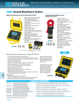
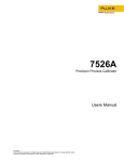
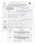
®
114, 115, 116, and 117
Digital Multimeters
Calibration Information
Introduction
XWWarning
To avoid electric shock or injury, do not perform the performance tests or
calibration adjustment procedures unless qualified to do so.
The information provided in this document is for the use of qualified personnel
only.
The 114, 115, 116, & 117 Calibration Information provides the information necessary to adjust and verify the
performance of the Fluke Models 114, 115, 115C, 116, 116C, 117, and 117C True RMS Multimeters (hereafter
known as the Meter). When specific models are noted in this manual, the “C” version is also included. For example,
when the listed model is 115, the instructions are applicable to the 115C as well.
The following information is included in this document:
•
•
•
•
•
•
•
•
•
Safety Information and International Electrical Symbols (page 2)
Specifications (page 3)
Testing the Fuse (page 5)
Replacing the Fuse and the Battery (page 6)
Cleaning (page 7)
Performance Tests (page 7)
Calibration Adjustment (page 12)
Replacement Parts and Accessories (page 17)
Complete Warranty (page 19)
See the 114, 115, 117 Users Manual or the 115C, 117C Users Manual or the 116 Users Manuals or the 116C Users
Manual for complete operating instructions.
Service Information
To contact Fluke, call one of the following telephone numbers:
USA: 1-888-99-FLUKE (1-888-993-5853)
Canada: 1-800-36-FLUKE (1-800-363-5853)
Europe: +31 402-675-200
Japan: +81-3-3434-0181
Singapore: +65-738-5655
Anywhere in the world: +1-425-446-5500
Or, visit Fluke's Web site at www.fluke.com.
To register your product, visit register.fluke.com
September 2006
©2006 Fluke Corporation. All rights reserved.
1
114, 115, 116, and 117
Calibration Information
Safety Information
"Warning" and "Caution" Statements
A “XW Warning" identifies hazardous conditions and actions that could cause bodily harm or death.
A "W Caution" identifies conditions and actions that could damage the Meter, the equipment under test, or cause
permanent loss of data.
XWWarnings and Precautions
To avoid possible electric shock or personal injury, follow these guidelines:
2
•
Use the Meter only as specified in this manual or the protection provided by
the Meter might be impaired.
•
Do not use the Meter or test leads if they appear damaged, or if the Meter is
not operating properly.
•
Always use proper terminals, switch position, and range for measurements.
•
Verify the Meter's operation by measuring a known voltage. If in doubt, have
the Meter serviced.
•
Do not apply more than the rated voltage, as marked on Meter, between
terminals or between any terminal and earth ground.
•
Use caution with voltages above 30 V ac rms, 42 V ac peak, or 60 V dc.
These voltages pose a shock hazard.
•
Disconnect circuit power and discharge all high-voltage capacitors before
testing resistance, continuity, diodes, or capacitance.
•
Do not use the Meter around explosive gas or vapor.
•
When using test leads or probes, keep your fingers behind the finger
guards.
•
Remove test leads from Meter before opening the battery door or Meter
case.
•
Comply with local and national safety requirements when working in
hazardous locations.
•
Use proper protective equipment, as required by local or national authorities
when working in hazardous areas.
•
Avoid working alone.
•
Use only the replacement fuse specified or the protection may be impaired.
•
Check the test leads for continuity before use. Do not use if the readings are
high or noisy.
•
Do not use the Auto-V LoZ function to measure voltages in circuits that
could be damaged by this function’s low input impedance (≈3 kΩ) (114, 116
and 117).
Digital Multimeters
International Electrical Symbols
International Electrical Symbols
Table 1 lists the international symbols that appear in this document and on the Meter.
Table 1. Electrical Symbols
Symbol
Description
Symbol
I
Description
B
AC (Alternating Current)
F
DC (Direct Current)
T
Double Insulated
X
Hazardous voltage
W
Important Information; Refer to manual
N
Battery (Low battery when shown on the
display.)
J
Earth ground
~
Do not dispose of this product as unsorted municipal waste. Contact Fluke or a qualified recycler for
disposal.
Fuse
Specifications
Accuracy is specified for 1 year after calibration at operating temperatures of 18 °C to 28 °C, with relative humidity at 0 % to 90 %. Extended
specifcifications are available at www.fluke.com.
General Specifications
Maximum voltage between any
terminal and earth ground ................................... 600 V
Surge Protection................................................... 6 kV peak per IEC 61010-1 600V CAT III,
Pollution Degree 2
W Fuse for A input (115 & 117 only):.................. 11 A, 1000 V FAST 17 kA Fuse (Fluke PN 803293)
Display ................................................................... Digital: 6,000 counts, updates 4/sec
Bar Graph: 33 segments, updates 32/sec
Temperature .......................................................... Operating: -10 °C to +50 °C
Storage: -40 °C to +60 °C
Temperature Coefficient ...................................... 0.1 x (specified accuracy)/°C (<18 °C or >28 °C)
Operating Altitude ................................................ 2,000 meters
Battery ................................................................... 9 Volt Alkaline, NEDA 1604A / IEC 6LR61
Battery Life ............................................................ Alkaline: 400 hours typical, without backlight
Safety Compliances.............................................. Complies with ANSI/ISA 82.02.01 (61010-1) 2004, CAN/CSA-C22.2 No 61010-1-04, UL 6101B
(2003) and IEC/EN 61010-1 2nd Edition for measurement Category III, 600 V, Pollution
Degree 2, EMC EN61326-1
Certifications ......................................................... UL, P, CSA, TÜV, ; (N10140), VDE
IP Rating (dust and water protection)................. IP42
3
114, 115, 116, and 117
Calibration Information
Accuracy Specifications
Function
Range
DC millivolts
DC Volts
[2]
Auto-V LoZ True-rms
[2]
AC millivolts True-rms
Resolution
600.0 mV
0.1 mV
6.000 V
0.001 V
60.00 V
600.0 V
0.01 V
0.1 V
600.0 V
0.1 V
600.0 mV
0.1 mV
Accuracy
± ([% of Reading] + [Counts])
Model
[1]
0.5 % + 2
114, 115, 116, 117
0.5 % + 2
114, 115, 116, 117
DC, 45 to 500 Hz
500 Hz to 1 kHz
2.0 % + 3
4.0 % + 3
45 to 500 Hz
500 Hz to 1 kHz
1.0 % + 3
2.0 % + 3
114, 115, 116, 117
1.0 % + 3
2.0 % + 3
114, 115, 116, 117
114, 116, 117
6.000 V
0.001 V
AC Volts True-rms
60.00 V
600.0 V
0.01 V
0.1 V
Continuity
600 Ω
1Ω
600.0 Ω
0.1 Ω
0.9 % + 2
6.000 kΩ
0.001 kΩ
0.9 % + 1
60.00 kΩ
0.01 kΩ
0.9 % + 1
600.0 kΩ
0.1 kΩ
0.9 % + 1
6.000 MΩ
40.00 MΩ
0.001 MΩ
0.01 MΩ
0.9 % + 1
1.5 % + 2
Diode test
2.000 V
0.001 V
0.9 % + 2
115, 116, 117
Capacitance
1000 nF
1 nF
1.9 % + 2
115, 116, 117
10.00 μF
0.01 μF
1.9 % + 2
100.0 μF
9999 μF
0.1 μF
1 μF
[2]
Ohms
Lo-Z Capacitance (Power-
1 nF to 500 μF
up option)
6.000 A
AC Amps True-rms
[2]
10.00 A
114, 115, 116, 117
114, 115, 116, 117
1.9 % + 2
100 μF - 1000 μF: 1.9 % + 2
>1000 μF: 5 % + 20
20% + 2
115, 116, 117
(10% +2 typical)
0.001 A
[4]
0.01 A
20 A overload for 30
(45 Hz to 500 Hz)
Beeper on <20 Ω, off >250 Ω; detects opens
or shorts of 500 μs or longer.
1.5 % + 3
115, 117
1.0 % + 3
115, 117
seconds maximum, 10
minutes rest minimum.
6.000 A
10.00 A
DC Amps
0.001 A
[4]
0.01 A
20 A overload for 30
seconds maximum, 10
minutes rest minimum.
Temperature (Type K
-40 °C to 400 °C
0.1 °C
1.0 % + 10
[5]
thermocouple)
-40 °F to 752 °F
0.2°F
1.0 % + 18
[5]
600.0 μA
0.1 μA
600.0 μA
0.1 μA
AC μAmps True-rms
(45 Hz to 1 kHz)
DC μAmps
4
[2]
116
1.5 % + 3 (2.5 % + 3 > 500 Hz)
116
1.0 % + 2
116
Digital Multimeters
Basic Maintenance
Accuracy Specifications (cont)
Function
Hz (V or A input)
[3]
Range
Resolution
99.99 Hz
0.01 Hz
999.9 Hz
0.1 Hz
9.999 kHz
50.00 kHz
0.001 kHz
0.01 kHz
Accuracy
± ([% of Reading] + [Counts])
Model
0.1 % + 2
[1]
115, 116, 117
Notes:
[1]
Models listed in this column also refer to the “C” version of the model. For example, those rows containing model 115 are applicable to the 115C
as well.
[2]
All ac ranges except Auto-V LoZ are specified from 1 % to 100% of range. Auto-V LoZ is specified from 0.0 V. Because inputs below 1 % of range
are not specified, it is normal for this and other true-rms meters to display non-zero readings when the test leads are disconnected from a circuit
or are shorted together. For volts, crest factor of ≤3 at 4000 counts, decreasing linearly to 1.5 at full scale. For amps, crest factor of ≤3. AC volts is
ac-coupled. Auto-V LoZ, AC mV, AC μamps, and AC amps are dc-coupled.
[3]
AC Volts Hz is ac-coupled and specified from 5 Hz to 50 kHz. AC Amps Hz is dc-coupled and specified from 45 Hz to 5 kHz.
[4]
>10 A unspecified.
[5]
Temperature uncertainty (accuracy) does not include the error of the thermocouple probe.
Input Characteristics
Input Impedance (Nominal)
Common Mode Rejection Ratio
(1 kΩ Unbalanced)
Volts AC
>5 MΩ <100 pF
>60 dB at dc, 50 or 60 Hz
Volts DC
>10 MΩ <100 pF
>100 dB at dc, 50 or 60 Hz
~3 kΩ <500 pF
>60 dB at dc, 50 or 60 Hz
Open Circuit Test Voltage
Full Scale Voltage
Function
Auto-V LoZ
Ohms
<2.7 V dc
Diode Test
<2.7 V dc
Normal Mode Rejection
>60 dB at 50 or 60 Hz
Short Circuit Current
To 6.0 MΩ
40 MΩ
<0.7 V dc
<0.9 V dc
2.000 V dc
<350 μA
<1.2 mA
Basic Maintenance
Testing the Fuse (115 & 117 only)
To test the fuse:
1. Set the rotary switch to Ω.
2. Plug a test lead into the v jack and touch the probe to the 10A jack, as shown in Figure 1.
If the display shows a resistance value in the range of that shown in Figure 1, the fuse is good.
If the display reads 0L, replace the fuse and test again.
If the display shows any other value, have the Meter serviced. See “Service Information” earlier in this document.
5
114, 115, 116, and 117
Calibration Information
VoltAle rt
LTIMETER
117 TRUE RMS MU
<.5
AUTO-V
LoZ
MIN MAX
OFF
OK
OK
Lo / H
HOLD
RANGE
Hz
V
V
mV
V olt
Alert
A
A
A Hz
V
COM
10 A
FUSED
erc010f.emf
Figure 1. Fuse Testing
Replacing the Battery and Fuse
XWWarning
To avoid shock, injury, or damage to the Meter:
•
Remove test leads from the Meter before opening the case or battery door.
•
Use ONLY a fuse with the amperage, interrupt voltage, and speed ratings
specified.
Battery
Fuse
erc011f.emf
Figure 2. Battery and Fuse Replacement
To remove the battery door for battery replacement, refer to Figure 2 while performing the following:
1. Remove the test leads from the Meter.
2. Remove the battery door screw.
3. Use the finger recess to lift the door slightly.
4. Lift the door straight up to separate it from the case.
5. The battery fits inside the battery door, which is then inserted into the case, bottom edge first, until it is
fully seated. Do not attempt to install the battery directly into the case.
6. Install and tighten battery door screw.
To open the case for fuse replacement, refer to Figure 2 while performing the following:
1. Remove the test leads from the Meter.
6
Digital Multimeters
Performance Tests
2. Remove the Meter from its holster.
3. Remove two screws from the case bottom.
4. Separate the case bottom from the case top.
5. Remove the fuse from its holder and replace with an 11 A, 1000 V, FAST fuse having a minimum
interrupt rating of 17,000 A. Use only Fluke PN 803293.
6. To re-assemble the Meter, attach the case bottom to the case top and secure with the two screws. Insert
the Meter into its holster.
Cleaning the Meter
Wipe the case with a damp cloth and mild detergent. Do not use abrasives or solvents. Dirt or moisture in the
terminals can affect readings.
Performance Tests
XWWarning
To avoid electric shock, do not perform the performance test procedures unless
the Meter is fully assembled.
The following performance tests verify the complete operation of the Meter and check the accuracy of each Meter
function against its specifications. The recommended calibration interval is 12 months. If the Meter fails any part of
the test, calibration adjustment and/or repair is indicated.
In the performance tests, the Meter is referred to as the unit under test (UUT).
Required Equipment
Table 2 lists the equipment required to conduct a performance test on the Meter.
Table 2. Required Equipment
Recommended Equipment
5500A Multi-product Calibrator (or
equivalent)
Measurement Function
Accuracy
DC Volts
10 mV to 600 V
±0.125 %
DC Current (115, 116, and 117)
600 μA to 10 A
±0.25 %
AC Volts
6 mV to 600 V
±0.25 % @ 45 Hz to 1 kHz
AC Current (115, 116, and 117)
600 μA to 10 A
±0.375 % @ 45 Hz to 1 kHz
Resistance
0 to 5 MΩ
±0.225 %
10 to 30 MΩ
±0.375 %
Capacitance (115, 116, and 117)
9 to 900 μF
±0.475 %
Temperature (116)
0 °C to 400 °C ±0.25 %
7
114, 115, 116, and 117
Calibration Information
Table 2. Required Equipment (cont)
Recommended Equipment
Measurement Function
5500A Multi-product Calibrator (or
equivalent)
Frequency (115, 116, and 117)
Fluke 80 AK
K-type Thermocouple Adapter Accessory
Temperature (116)
K-type Thermocouple, mini-plug on both
ends
Temperature (116)
Double Banana plug
VoltAlert (117)
Accuracy
2 V, 50 kHz
±0.025 %
Testing the Display
Push K and turn the rotary switch to the e position. Compare the display with the example in Figure 3.
Check all segments for clarity and contrast.
erc022f.emf
Figure 3. Display Segments
Backlight Test
To Test the Backlight, press the Q button and verify that the backlight comes on.
Keypad Test
To test the keypad, turn the Meter to ACV and push each button separately. Each button push should cause the
Meter to beep and activate a display annunciator.
Reset the Meter by turning it Off and then back to an On position.
Preparing for the Performance Tests
XWWarning
To avoid possible electric shock or personal injury:
•
Do not perform the following procedures unless qualified to do so. Some
procedures involve the use of high voltages.
•
Before handling the test connections and in between tests, make sure
the calibrator is in standby mode (STBY).
To prepare for the performance test:
1. Make sure that you have the required equipment (refer to Table 2).
8
Digital Multimeters
Performance Tests
2. Warm up the calibrator as required by its specifications.
3. Allow the temperature of the UUT to stabilize at room temperature (23 °C ± 5 °C [73 °F ± 9 °F] ).
4. Check the fuses and Battery, and replace them if necessary. Refer to “Testing the Fuses”, and
“Replacing the Battery and Fuse”.
To verify the accuracy of the DMM functions, do the following:
1. Connect the Calibrator to the VΩ and COM input terminals on the Meter.
2. Turn the rotary switch to the function listed in each step of Table 3.
3. Apply the input level for each step listed in Table 3.
4. Compare the reading on the Meter display with the Display Reading in Table 3.
5. If the display reading falls outside of the range shown in Table 3, the Meter requires calibration
adjustment or repair.
Testing Temperature (116 only)
Connect the K-type thermocouple to the temperature input of the Meter and temperature calibrator. To ensure an
accurate measurement, the Meter and the thermocouple connector must be at the same temperature. After connecting
the thermocouple to the Meter, allow the junctions to stabilize before recording the displayed reading. This can take
several minutes, depending on temperature gradients.
Table 3. DMM Performance Tests
Display Reading
Step
Function
Range
Applied
114[1]
115[1]
116[1]
600.0
0.0 Ω
0.0 to 0.2
600.0
500 Ω
495.3 to 504.7
3
6.000 k
5 kΩ
4.954 to 5.046
4
60.00 k
50 kΩ
49.54 to 50.46
5
600.0 k
500 kΩ
495.4 to 504.6
6
6.000 M
5 MΩ
4.954 to 5.046
7
40.00 M
10 MΩ
9.83 to 10.17
8
40.00 M
30 MΩ
29.53 to 30.47
R
Continuity
600 Ω
20 Ω
Beeper On
600 Ω
250 Ω
Beeper Off
K
6.000 V
5V, 45 Hz
4.947 to 5.053
6.000 V
5V, 1 kHz
4.897 to 5.103
13
60.00 V
50 V, 45 Hz
49.47 to 50.53
14
60.00 V
50V, 1 kHz
48.97 to 51.03
15
600.0 V
600V, 45 Hz
593.7 to 606.3
16
600.0 V
600V, 1kHz
587.7 to 612.3
6.000V
2 v, 45 kHz[1]
1
2
9
10
11
12
17
e
Ohms
AC Volts
e
AC Volts + Hz
NA
117[1]
49.93 to 50.07
9
114, 115, 116, and 117
Calibration Information
Table 3. DMM Performance Tests (cont)
Display Reading
Step
Function
Range
Applied
[1]
114
18
L
115[1]
116[1]
6.000V
0V
-0.002 to 0.002
6.000V
5V
4.973 to 5.027
20
60.00V
50V
49.73 to 50.27
21
600.0V
600V
596.8 to 603.2
22
600.0V
-600V
-596.8 to -603.2
600.0 mV
6 mV, 45 Hz
600.0 mV
600mV, 1 kHz
600.0 mV
10 mV
9.7 to 10.3
600.0 mV
600mV
596.8 to 603.2
19
23
24
25
26
DC Volts
m
AC Millivolts
•
DC Millivolts
117[1]
5.6 to 6.4
587.7 to 612.3
27
G Diode
2.000 V
1.9V
N/A
28
E
Capacitance
1000 nF
Open
N/A
0 to 2
0 to 2
0 to 2
9999 μF
900 μF
N/A
881 to 919
881 to 919
881 to 919
9 μF
N/A
29
30
LoZ
Capacitance
10.00 μF
1.881 to 1.919
7.18 to 10.82
Set calibrator to standby, reconfigure leads, and program for amps output
31
A
DC Amps
10.00 A
10A
N/A
9.87 to
10.13
N/A
9.87 to
10.13
32
?
AC Amps
6.000 A
5.0A, 45 Hz
N/A
4.922 to
5.078
N/A
4.922 to
5.078
600.0 μA
600 μADC
N/A
N/A
593.8 to
606.2
N/A
600.0 μA
600 μAAC, 45 Hz
N/A
N/A
590.7 to
609.3
N/A
Open input
N/A
N/A
0PEn
N/A
0.0 °C
N/A
N/A
-1.0 to 1.0
N/A
400 °C
N/A
N/A
395.0 to
405.0
N/A
N/A
0.2 to 0.8,
AC
Annunciator
On
0.2 to 0.8,
AC
Annunciator
On
0.2 to 0.8,
DC
Annunciator
On
N/A
0.2 to 0.8,
DC
Annunciator
On
0.2 to 0.8,
DC
Annunciator
On
489.7 to
510.3
N/A
489.7 to
510.3
489.7 to
510.3
33
$
DC μamps
34
$
AC μamps
35
36
y
Temperature
37
38
39
40
10
x
0.5 V, 45 Hz
0.5 V, 0 Hz
500 V[2],
500 Hz
0.2 to 0.8,
AC
Annunciator
On
Digital Multimeters
Performance Tests
Table 3. DMM Performance Tests (cont)
Display Reading
Step
Function
Range
Applied
[1]
114
41
VoltAlert
VoltAlert
116[1]
117[1]
N/A
Refer to
steps 1 – 5
in the
procedure
below
N/A
Refer to
steps 6 – 9
in the
procedure
below
Hi
N/A
42
115[1]
N/A
Lo
N/A
N/A
[1] If using a Fluke 9100 calibrator, the Calibrator Frequency mode must be used to obtain accurate frequency.
[2] To keep from tripping the calibrator to standby, ramp up the voltage in 50 V increments with a 5 second delay between
increments.
Testing the VoltAlert Function (117 only)
Use the following procedure to verify that VoltAlert functions properly.
•
Note
Ensure the instrument is REMOVED from the holster prior to performing the test.
•
Keep the meter away from electrical noise sources during the tests, i.e., florescent
lights, dimmable lights, motors, etc.. These sources can trigger VoltAlert and
invalidate the test.
•
It may be necessary in steps 4 and 8 below to slightly adjust the Meter’s position for
maximum signal strength, in order to get the Meter’s beeper to sound continuously.
Refer to Figure 4 while performing the following steps.
1. Select the VoltAlert function, and verify that “Hi” is on the display. Verify that the beeper is silent and
the red LED is off.
2. Connect a double banana plug to the output voltage terminals of the calibrator (Fluke 5500A or
equivalent).
3. Set the calibrator output to 10 V at 60 Hz.
4. Hold the Meter so that the Meter’s top is vertically and horizontally centered and contacting the banana
plug’s Hi terminal. Verify that the Meter’s beeper is on continuously, and the red LED, at the top of the
display, lights up.
5. Place the calibrator in standby mode and verify that the beeper is now silent and the red LED is off.
6. Press the q(display should indicate ‘Lo’ range).
7. Set the calibrator’s output to 30 V at 60 Hz.
11
114, 115, 116, and 117
Calibration Information
NORMAL
AUX
V RTD
A SENS
E A UX V
SCOPE
OUT
7
TRIG
8
4
5
VoltAlert
117 TRUE RMS MULTIMETER
S TB Y
.
2
+/0
.
Insert Double Banana
Center Meter top on Hi terminal.
Note that LED is RED
erc013f.emf
Figure 4. VoltAlert Testing
8. Hold the Meter so that the top is vertically and horizontal centered to the banana plug’s Hi terminal.
Verify that the Meter’s beeper is sounding continuously and the red LED at the top of the display lights.
9. Return the calibrator to standby mode and verify the Meter’s beeper is silent and the red LED is off.
Calibration Adjustment
The Meter features closed-case calibration adjustment using known reference sources. The Meter measures the
applied reference source, calculates correction factors, and stores the correction factors in nonvolatile memory.
The following sections present the features and Meter pushbutton functions available during the Calibration
Adjustment Procedure. Should the Meter fail any of the performance tests, perform the Calibration Adjustment
Procedure.
Use the following steps to view the Meter’s calibration counter.
1. While pressing K, turn the rotary switch from OFF to Ω function. The Meter should display
“ZCAL”.
2. Press g once to view the calibration counter. For example, “n001”
3. Turn the rotary switch to OFF.
Calibration Adjustment Password
To start the Calibration Adjustment Procedure, the correct 4-digit password must be entered. The default password is
“1234”. The password can be changed or reset to the default as described in following paragraphs.
Changing the Password
Use the following steps to change the Meter’s password:
1. While pressing K, turn the rotary switch from OFF to Ω function. The Meter should display
“ZCAL”.
12
Digital Multimeters
Calibration Adjustment
2. Press g once to see the calibration counter.
3. Press g again to start the password entry. The Meter displays “?>>>”
4. The Meter buttons indicated below represent the numbers 1 through 5 when entering or changing the
password:
K=1
M=2
q=3
g=4
Q=5
5. Press 4 buttons to enter the current password. If changing the password for the first time, enter
K (1), M (2), q (3), and g (4).
6. Press qto change the password. The Meter displays “////” if the entered password is correct. If the
password is not correct, the Meter emits a double beep, displays “?>>>”, and the password must be
entered again. Repeat step 5.
7. Press the 4 buttons of the new password.
8. Press g to store the new password.
Restoring the Default Password
If the calibration password is forgotten, the default password (1234) can be manually restored using the following
steps:
XW Warning
To avoid electric shock or personal injury, remove the test leads and any input
signal before removing the Meter’s back case.
1. Remove the Meter’s back case. Leave the pca in the top case.
2. Apply 9.0V across the battery contacts (XBT1) + and (XBT2) – on the back of the PCA. See Figure 5.
3. Turn the rotary switch from OFF to any on position.
4. Short across the S7 CAL keypad on the back of the PCA. See Figure 5. The Meter should beep. The
default password is now restored.
5. Remove the 9.0V supply and replace the Meter’s back case.
Short S7 to reset to Default password
XBT1
erc12f.emf
Figure 5. Calibration Password Reset
13
114, 115, 116, and 117
Calibration Information
Meter Buttons Used in the Calibration Steps
When performing the Calibration Adjustment Procedure, the Meter buttons behave as follows. This may be of help
determining why a calibration step is not accepted and for determining the input value without referring to Table 4.
Press and hold K to show the measured value. The measured value is not calibrated so it may not match the
input value. This is normal.
Press and hold M to display the required input value.
Press g to store the calibration value and advance to the next step. This button is also used to exit calibration
mode after the calibration adjustment sequence is complete.
Press Q to toggle the backlight on and off.
Calibration Adjustment Procedure
To adjust the Meter’s calibration, use the following steps. If the Meter is turned off before completion of the
adjustment procedure, the calibration constants are not changed.
1. While holding down K, turn the rotary switch from OFF to Ω function. The Meter should display
“ZCAL”.
2. Press g once to see the calibration counter.
3. Press g again to start the password entry. The Meter displays “?>>>”.
4. Press the 4 button password.
5. Press g to go to the first calibration step. The Meter displays “C/01” if the password is correct. If the
password is not correct, the Meter emits a double beep, displays “?>>>” and the password must be
entered again. Repeat step 4.
6. Apply the input value listed for each calibration adjustment step. For each step, select the rotary switch
position and apply the input to the terminals as indicated in the Table 4.
Note
Some adjustment steps require additional wait time after the calibrator settles, as noted in
Table 4.
7. After each input value is applied, press g to accept the value and proceed to the next step (C/02 and
so forth).
Notes
After pressing g, wait until the step number advances before changing the calibrator
source or turning the Meter’s rotary knob. Some adjustment steps can take up to several
seconds to execute before moving to the next step.
If the knob is not in the correct position for a given step, the meter will flash the unit
annunciators until the knob is put in a valid position. The keys that show the reading and
required input values are not allowed until the knob is correct.
Likewise, if the rotary switch is not in the correct position or the measured value is not within
the anticipated range of the input value, the Meter will emit a double beep and will not
continue to the next step when g is pressed.
8. After the final step, the display shows “End” to indicate that the calibration adjustment is complete.
Press g to return to meter mode.
14
Digital Multimeters
Calibration Adjustment
Notes
Set the calibrator to Standby prior to changing the function switch position and after
completing adjustment of each function.
If the calibration adjustment procedure is not properly completed, the Meter will not operate
correctly.
Table 4. Calibration Adjustment Steps
Rotary
Switch
Position
e
Calibration Steps
114
[1]
115
[1]
116
[1,2]
117
Input
Terminals
Calibrator
Source Value
N/A
C/01
C/01
C/01[2]
No leads
No leads
C/01
C/02
C/02
C/02
VΩ/+ and COM
0 V, 0 Hz
C/02
C/03
C/03
C/03
VΩ/+ and COM
300 mV, 0 Hz
C/03
C/04
C/04
C/04
VΩ/+ and COM
100 mV, 0 Hz
C/04
C/05
C/05
C/05
VΩ/+ and COM
-300 mV, 0 Hz
C/05
C/06
C/06
C/06
VΩ/+ and COM
60 mV, 0 Hz
C/06
C/07
C/07
C/07
VΩ/+ and COM
600 mV, 0 Hz
C/07
C/08
C/08
C/08
VΩ/+ and COM
600 mV, 60 Hz
C/08
C/09
C/09
C/09
VΩ/+ and COM
600 e, 2-wire comp
C/09
C/10
C/10
C/10
VΩ/+ and COM
6 ke
C/10
C/11
C/11
C/11
VΩ/+ and COM
60 ke
C/11
C/12
C/12
C/12
VΩ/+ and COM
600 ke
C/12
C/13
C/13
C/13
VΩ/+ and COM
6 Me[3]
C/13
C/14
C/14
C/14
VΩ/+ and COM
Short[3]
C/14
C/15
C/15
C/15
VΩ/+ and COM
40 Me[3]
C/15
C/16
C/16
C/16
VΩ/+ and COM
6 V, 60 Hz
C/16
C/17
C/17
C/17
VΩ/+ and COM
60 V, 60 Hz
C/17
C/18
C/18
C/18
VΩ/+ and COM
600 V, 60 Hz
C/18
C/19
C/19
C/19
VΩ/+ and COM
6 V, 0 Hz
C/19
C/20
C/20
C/20
VΩ/+ and COM
60 V, 0 Hz
C/20
C/21
C/21
C/21
VΩ/+ and COM
600 V, 0 Hz
Ohms
m
e
Ohms
K
Set calibrator to standby, reconfigure leads, and program for amps output.
?
N/A
C/22
N/A
C/22
A and COM
6 A, 60 Hz[3]
A
N/A
C/23
N/A
C/23
A and COM
6 A, 0 Hz
$
N/A
N/A
C/22
N/A
+ and COM
600 μA, 60 Hz
AC μamps
15
114, 115, 116, and 117
Calibration Information
Table 4. Calibration Adjustment Steps (cont)
Rotary
Switch
Position
$
Calibration Steps
114
N/A
[1]
115
N/A
[1]
116
C/23
[1,2]
117
N/A
Input
Terminals
+ and COM
Calibrator
Source Value
600 μA, 0 Hz
DC μamps
16
[1]
Models listed in this column also refer to the “C” version of the model. For example, model 115 steps are valid for the 115C.
[2]
Do not calibrate the 117 or 117C with a line-frequency power source nearby (e.g. fluorescent light, power strip, etc.). These devices
can produce errors in the VoltAlert calibration.
[3]
Wait an additional 5 seconds after calibrator has settled before pressing g.
Digital Multimeters
Replacement Parts
Replacement Parts
Table 5 lists the Meter’s replacable parts identified in Figure 6.
6
5
8
12
3
9
1
10
4
2
7
11
15 4 PL
23
13
16
17
2 PL
19
20
14
18
21
22
erc14.emf
Figure 6. Exploded View of Meter
17
114, 115, 116, and 117
Calibration Information
Table 5. Replacable Parts List
Item
Description
Part
Number
Qty.
1
LCD,FLUKE-11X,3.2V,TN,4-DIGIT,1/4-DUTY,1/3-BIAS,LEPTON
2509955
2
CONNECTOR,ELASTOMERIC,.010 IN CTR,.218 IN HIGH,.090 IN
THK,2.284 IN LONG,BULK
2534229
FLUKE-117-2006,BRACKET MASK, 117
2525608
1
FLUKE-117-2006-06,BRACKET MASK, 117 China
2631059
1
FLUKE-117-2006-01,BRACKET MASK, 114
2527431
1
FLUKE-117-2006-02,BRACKET MASK, 115
2527446
1
FLUKE-117-2006-04,BRACKET MASK, 115 China
2631032
1
FLUKE-117-2006-03,BRACKET MASK, 116
2527454
1
FLUKE-117-2006-05,BRACKET MASK, 116 China
2631044
1
4
FLUKE-117-8005,DIFFUSER, BACKLIGHT
2535203
1
5
FLUKE-117-2001,CASE TOP, 117
2525553
1
FLUKE-117-2001-01,CASE TOP, 114
2527405
1
FLUKE-117-2001-02,CASE TOP, 115
2527410
1
FLUKE-117-2001-03,CASE TOP, 116
2527422
1
6
FLUKE-117-2008,KNOB
2525624
1
7
FLUKE-117-7602,RSOB HOUSING ASSEMBLY
2787083
1
8
FLUKE-117-8001,KEYPAD
2526276
1
9
FLUKE-117-2009,SPRING DETENT
2525636
1
10
FLUKE-117-8009,SHIELD, TOP
2571277
1
11
FLUKE-117-8010,IC SHIELD
2571292
1
12
O-RING,NITRILE,SHORE A 70,15.6MM OD,12.0MM ID ,1.8MM W
2535215
1
13
FLUKE-117-2002,CASE BOTTOM
2525566
1
FLUKE-117-2002,CASE BOTTOM, 11X China
2631098
1
FLUKE-117-2003,BATTERY DOOR
2525575
1
FLUKE-117-2003,BATTERY DOOR, 11X China
2631067
1
SCREW,2-28,.250,PAN,PHILLIPS,STEEL,ZINCCHROMATE,PLASTITE 48 THREAD FORMING
2516493
3
14
15
16
17
18
18
SCREW,M3,4MM,PAN,PHILLIPS,STEEL,ZINC-CHROMATE
1
1
4
2032811
SCREW,5-14,.750,PAN,PHILLIPS,STEEL,BLACK
CHROMATE,THD FORMING
832246
SCREW,M3X0.5,6MM,PAN,PHILLIPS,STEEL,ZINC-BLACK
CHROMATE
2032792
2 (114, 116)
3 (115, 117)
2
1
Digital Multimeters
Warranty
Table 5. Replaceable Parts List
Item
Part
Number
Description
Qty.
BATTERY,PRIMARY,MNO2ZN,9V,505MAH,6LR61,ALKALINE, 17X26X48MM,BULK
614487
20
FLUKE 12-8004,SHOCK ABSORBER
878983
1
21
FLUKE-117-2005,TILT STAND
2525594
1
FLUKE-117-2005,TILT STAND, 11X China
2631071
1
FLUKE-117-2010,HOLSTER
2525649
1
FLUKE-117-2010,HOLSTER, 11X China
2631080
1
23
FUSE,11A,1000V,FAST.406INX1.5IN,BULK
803293
1 (115, 117)
Not shown
MANUAL,114/115/117 USERS MANUAL, EFSPAsia
2538674
1
Not shown
MANUAL,114/115/117 USERS MANUAL, EFG(Eur)
2572573
1
Not shown
MANUAL,115C/117C USERS MANUAL
2538695
1
Not shown
MANUAL,116 USERS MANUAL, EFSPAsia
2538688
1
Not shown
MANUAL,116 USERS MANUAL, EFG(Eur)
2572586
1
Not shown
MANUAL,116C USERS MANUAL
2538707
1
19
22
1
Warranty
This Fluke product will be free from defects in material and workmanship for three years from the date of purchase. This warranty
does not cover fuses, disposable batteries, or damage from accident, neglect, misuse, alteration, contamination, or abnormal
conditions of operation or handling. Resellers are not authorized to extend any other warranty on Fluke’s behalf. To obtain service
during the warranty period, contact your nearest Fluke authorized service center to obtain return authorization information, then
send the product to that Service Center with a description of the problem.
THIS WARRANTY IS YOUR ONLY REMEDY. NO OTHER WARRANTIES, SUCH AS FITNESS FOR A PARTICULAR
PURPOSE, ARE EXPRESSED OR IMPLIED. FLUKE IS NOT LIABLE FOR ANY SPECIAL, INDIRECT, INCIDENTAL OR
CONSEQUENTIAL DAMAGES OR LOSSES, ARISING FROM ANY CAUSE OR THEORY. Since some states or countries do
not allow the exclusion or limitation of an implied warranty or of incidental or consequential damages, this limitation of liability may
not apply to you.
Fluke Corporation
P.O. Box 9090
Everett, WA 98206-9090
U.S.A.
Fluke Europe B.V.
P.O. Box 1186
5602 BD Eindhoven
The Netherlands
11/99
19
114, 115, 116, and 117
Calibration Information
20