1
Maintenance and Modifications
The HSA surface mount enclosures can be modified in the
future to replace an AAP or to change the color or appearance of
the bezel plug-ins. The most probable corrective maintenance
procedures required are leveling the top surface and adjusting
its height and replacing the gas lift. Most of the maintenance
procedures require removing the surface mount enclosure from
the table.
4.
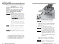
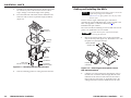
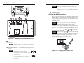
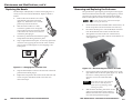
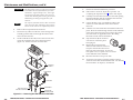
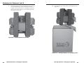
Remove the AAP(s) to be replaced from the front panel by
unscrewing the nuts on the rear of the panel that fasten the
plates to the faceplate (figure 3-2).
#4-40 Nut with Captive
Washer
12
5
50
/60
Hz
0.5
A
Front Panel
HS
A4
00
Replacing an AAP
Replace one or more AAPs as follows:
Ensure that AC power is disconnected before
servicing the HSA unit.
1.
On the underside of the clamshell and in the enclosure, cut
the tie wraps that route the AAP cables out of the way.
2.
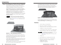
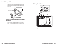
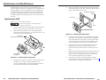
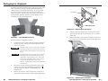
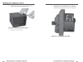
Remove the four hex head screws on the right and left
sides of the front panel (figure 3-1). Retain the screws. Lift
the panel away from the enclosure.
Remove two
Allen screws on each side.
125
-
50/6
0H
z 5A
Cable
IN
SE PUT
LE
CT
IN
SELEPUT
CT
RG
B
SI
AA
P
3.
3-2
Disconnect any cables from the rear of the AAPs that are to
be replaced. If a cable is no longer required in your
system, carefully pull the cable out through the bottom of
the surface mount enclosure and the clamshell.
HSA 400/402 Series • Maintenance and Modifications
AU
DIO
ER
5.
Cable the rear of the AAPs to be installed before attaching
the AAPs to the enclosure. Route the cables through the
hole in the underside of the surface mount enclosure and
connect them to the rear of the AAPs. If applicable, refer
to the cabling information in the AAP documentation.
6.
Insert each AAP’s screws through the holes in the AAP
opening of the front panel. Secure each AAP to the
enclosure with the provided captive washers and #4-40
nuts.
7.
Replace the front panel in the surface mount enclosure and
secure it in place with the hex head screws removed in
step 2. If you lose a front panel screw, two spare screws
are stored in the underside of the clamshell.
8.
To prevent wear and tear caused by cable movement,
secure the AAP cables underneath the table. See “Routing
the AAP Cables” in chapter 2, “Installation”.
Lift panel out
of enclosure.
Figure 3-1 — Removing the front panel
UT
Figure 3-2 — Mounting an AAP device
CO
AU
MPU
DIO
TER
580
xi
MP
RGB 580xi SI AAP
HSA
400
H. SH
IFT
CO
HSA 400/402 Series • Maintenance and Modifications
3-3