1
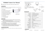
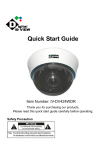
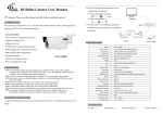
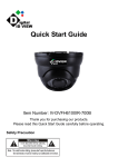
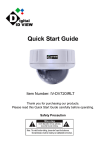
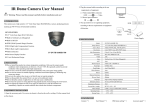
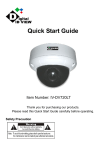
Low Profile VESA Mount Kit User Guide
Overview
Tongue
The Extron® Low Profile VESA® Mount Kit (LPVM-1) allows
monitors or Extron touch panels to be wall mounted to a two-gang
UL‑certified junction box, a two-gang mud ring, or directly onto
any solid surface, such as brick, wood, masonry, or drywall. The kit
supports both the B-type (20 x 50 mm) and D-type (75 x 75 mm)
VESA mounting patterns. The monitor attaches to the wall at a fixed
angle with no tilting.
Holes to Secure
Plate 1 to Wall
Bottom Tabs (2)
Holes to Secure
Plate 1 to Mud Ring
or Junction Box
CAUTION: The maximum loads for the LPVM-1 are:
VESA B — 4.4 pounds (2 kg)
VESA D — 30.8 pounds (14 kg) if the LPVM-1 is
mounted directly to the wall, not a mud ring.
Extron LPVM-1
Plate 1
The kit consists of two separate steel plates, held together by two
locking screws. Plate 1, which attaches to the wall, has a protruding
tongue at the top. The tongue fits into a groove at the top of plate
2, which attaches to the back of the display device (see the figure at
right).
Groove
B-Type VESA
Mount Holes
D-Type VESA
Mount Holes
Optional Tools and Equipment
Locking Screws
(#10-32 Phillips)
To mount the LPVM-1, you may need some or all of the following
items that are not provided by Extron:
Bottom Edge
•
Mud ring or UL-certified junction box
•
Tools for cutting a hole in drywall
•
Conduit or surface raceway
•
Power drill with a bit that is appropriate for the wall type
•
Screwdriver
•
Four screws or bolts, to attach the LPVM-1 to the wall (these must be appropriate for the type of wall).
Extron LPVM-1
Plate 2
Installation Instructions
To VESA mount a touch panel or monitor using the LPVM-1, follow these instructions:
3
Disassembling the LPVM-1
1. Use a Phillips screwdriver to loosen the two locking screws until the two plates of the
LPVM-1 can separate.
2. Swing the bottom tabs of plate 1 away from the bottom edge of plate 2.
3. Pull plate 1 down to remove the tongue from the groove in plate 2.
1
4. Select a suitable mounting site and decide whether the LPVM-1 will be mounted directly
to the wall (see below), or to a mud ring or UL-certified junction box (see the next page).
2
Mounting the LPVM-1 Directly to a Wall:
a. If the LPVM-1 is being mounted directly to drywall, you may cut a
hole in the drywall that is 2.5 x 2.5 inches (6.35 x 6.35 cm) to run
cables inside the wall cavity. If the LPVM-1 is attached to a solid wall
or you do not want to run cables through the drywall cavity, the
cables should be enclosed in conduit or raceway.
4b
4c
b. Use plate 1 to mark the position of the four holes in the wall and
drill four holes, using a drill bit that is appropriate for the wall type.
Plate 1 accommodates screws up to 1/4 inch in diameter.
c. Secure plate 1 to the wall with four screws or bolts that are
appropriate for the wall type. Ensure the tongue is facing up.
Screws (4)
Appropriate
to Wall Type
Low Profile VESA Mount Kit User Guide (Continued)
Mounting the LPVM-1 to a Mud Ring or UL-Certified Junction Box in Drywall:
NOTE: See the caution on previous page about
weight restrictions.
a. Follow the instructions provided by the manufacturer
to cut the hole and install the mud ring or junction
box.
b. Attach plate 1 to the mud ring or junction box, using
UL-certified
2-gang
Wall Box
the four #6‑32 screws provided. Ensure the tongue is
facing upwards.
c. Connect conduit to the junction box and run the
cables to the installation site.
#6-32 screws (4)
Extron
LPVM-1
Mounting the Display Device
Plate 1
5. If necessary, remove all cables from the display device.
NOTE: To VESA mount the TLP 700TV, it is necessary to remove
the base and the plastic enclosure from the back. For
full instructions, see the TLP 700MV and TLP 700TV User
Guide, which is available from www.extron.com.
Do not use the VM 700T for mounting with the LPVM‑1.
Use the four 12 mm M4 screws (provided) to attach plate 2 to the
back of the display device, using either the B-type (20 x 50 mm) or
D‑type (75 x 75 mm) VESA mounting pattern. The plate should be
attached securely but do not over-tighten the screws.
6. Attach the cables to the back of the display device. Feed any excess
cable back into the wall, conduit, or raceway. Follow all information
in the user manual provided with the display device to ensure the
cables and power are connected correctly.
Monitor w/ B-type
VESA Mount
12 mm M4
Screws (4)
Plate 2
7. Check the display device is working correctly (see the user manual for the
display device).
8
8. Hook plate 2 to plate 1 by holding the display at a slight angle so that the
Plate 1
groove of plate 2 is over the tongue in plate 1. Lower the display device so
that the tongue enters the groove as far as possible.
9. Allow the bottom of the display to move inwards so that the display is
parallel to the wall and the bottom tabs of plate 1 are seated over the
bottom edge of plate 2.
Plate 2
10.Lock the two plates together by tightening the two locking screws with a
9
screwdriver (do not over-tighten).
10
Extron USA - West
Extron USA - East
Extron Europe
Extron Asia
Extron Japan
Extron China
Extron Middle East
+800.633.9876
Inside USA/Canada Only
+800.633.9876
Inside USA/Canada Only
+800.3987.6673
Inside Europe Only
+800.7339.8766
Inside Asia Only
+81.3.3511.7655
+81.3.3511.7656 FAX
+400.833.1568
Inside China Only
+971.4.2991800
+971.4.2991880 FAX
+1.714.491.1500
+1.714.491.1517 FAX
+1.919.863.1794
+1.919.863.1797 FAX
+31.33.453.4040
+31.33.453.4050 FAX
+65.6383.4400
+65.6383.4664 FAX
Headquarters
© 2010 Extron Electronics. All Rights Reserved.
+86.21.3760.1568
+86.21.3760.1566 FAX
www.extron.com
68-1946-01
Rev A
06 10