1
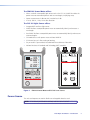
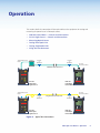
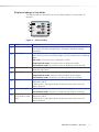
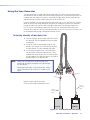
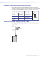
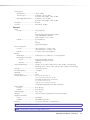
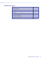
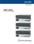
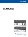
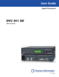
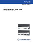
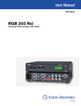
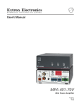
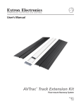
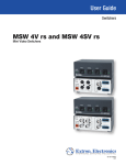
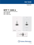
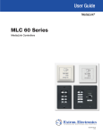
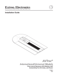
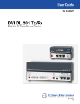
User Guide
Fiber Optic Connectors and Accessories
FPM 101 / FLS 101
Fiber Optic Test Set
68-2047-01 Rev. A
06 11
Safety Instructions • English
Warning
This symbol is intended to alert the user of important operating and maintenance (servicing) instructions in the literature provided with the equipment.
Power sources • This equipment should be operated only from the power source indicated on the product. This
equipment is intended to be used with a main power system with a grounded (neutral) conductor. The third
(grounding) pin is a safety feature, do not attempt to bypass or disable it.
This symbol is intended to alert the user of the presence of uninsulated
dangerous voltage within the product’s enclosure that may present a risk of
electric shock.
Power disconnection • To remove power from the equipment safely, remove all power cords from the rear of
the equipment, or the desktop power module (if detachable), or from the power source receptacle (wall plug).
Caution
Read Instructions • Read and understand all safety and operating instructions before using the equipment.
Retain Instructions • The safety instructions should be kept for future reference.
Follow Warnings • Follow all warnings and instructions marked on the equipment or in the user information.
Avoid Attachments • Do not use tools or attachments that are not recommended by the equipment
manufacturer because they may be hazardous.
Consignes de Sécurité • Français
Ce symbole sert à avertir l’utilisateur que la documentation fournie avec le
matériel contient des instructions importantes concernant l’exploitation et la
maintenance (réparation).
Ce symbole sert à avertir l’utilisateur de la présence dans le boîtier
de l’appareil de  tensions dangereuses non isolées posant des risques
d’électrocution.
Attention
Lire les instructions• Prendre connaissance de toutes les consignes de sécurité et d’exploitation avant
d’utiliser le matériel.
Conserver les instructions• Ranger les consignes de sécurité afin de pouvoir les consulter à l’avenir.
Respecter les avertissements • Observer tous les avertissements et consignes marqués sur le matériel ou
présentés dans la documentation utilisateur.
Eviter les pièces de fixation • Ne pas utiliser de pièces de fixation ni d’outils non recommandés par le
fabricant du matériel car cela risquerait de poser certains dangers.
Sicherheitsanleitungen • Deutsch
Power cord protection • Power cords should be routed so that they are not likely to be stepped on or pinched
by items placed upon or against them.
Servicing • Refer all servicing to qualified service personnel. There are no user-serviceable parts inside. To prevent
the risk of shock, do not attempt to service this equipment yourself because opening or removing covers may
expose you to dangerous voltage or other hazards.
Slots and openings • If the equipment has slots or holes in the enclosure, these are provided to prevent
overheating of sensitive components inside. These openings must never be blocked by other objects.
Lithium battery • There is a danger of explosion if battery is incorrectly replaced. Replace it only with the
same or equivalent type recommended by the manufacturer. Dispose of used batteries according to the
manufacturer’s instructions.
Avertissement
Alimentations • Ne faire fonctionner ce matériel qu’avec la source d’alimentation indiquée sur l’appareil. Ce
matériel doit être utilisé avec une alimentation principale comportant un fil de terre (neutre). Le troisième
contact (de mise à la terre) constitue un dispositif de sécurité : n’essayez pas de la contourner ni de la
désactiver.
Déconnexion de l’alimentation• Pour mettre le matériel hors tension sans danger, déconnectez tous les
cordons d’alimentation de l’arrière de l’appareil ou du module d’alimentation de bureau (s’il est amovible) ou
encore de la prise secteur.
Protection du cordon d’alimentation • Acheminer les cordons d’alimentation de manière à ce que personne
ne risque de marcher dessus et à ce qu’ils ne soient pas écrasés ou pincés par des objets.
Réparation-maintenance • Faire exécuter toutes les interventions de réparation-maintenance par un
technicien qualifié. Aucun des éléments internes ne peut être réparé par l’utilisateur. Afin d’éviter tout danger
d’électrocution, l’utilisateur ne doit pas essayer de procéder lui-même à ces opérations car l’ouverture ou le
retrait des couvercles risquent de l’exposer à de hautes tensions et autres dangers.
Fentes et orifices • Si le boîtier de l’appareil comporte des fentes ou des orifices, ceux-ci servent à empêcher les
composants internes sensibles de surchauffer. Ces ouvertures ne doivent jamais être bloquées par des objets.
Lithium Batterie • Il a danger d’explosion s’ll y a remplacment incorrect de la batterie. Remplacer uniquement
avec une batterie du meme type ou d’un ype equivalent recommande par le constructeur. Mettre au reut les
batteries usagees conformement aux instructions du fabricant.
Vorsicht
Dieses Symbol soll dem Benutzer in der im Lieferumfang enthaltenen
Dokumentation besonders wichtige Hinweise zur Bedienung und Wartung
(Instandhaltung) geben.
Stromquellen • Dieses Gerät sollte nur über die auf dem Produkt angegebene Stromquelle betrieben werden.
Dieses Gerät wurde für eine Verwendung mit einer Hauptstromleitung mit einem geerdeten (neutralen) Leiter
konzipiert. Der dritte Kontakt ist für einen Erdanschluß, und stellt eine Sicherheitsfunktion dar. Diese sollte nicht
umgangen oder außer Betrieb gesetzt werden.
Dieses Symbol soll den Benutzer darauf aufmerksam machen, daß im Inneren
des Gehäuses dieses Produktes gefährliche Spannungen, die nicht isoliert sind
und die einen elektrischen Schock verursachen können, herrschen.
Stromunterbrechung • Um das Gerät auf sichere Weise vom Netz zu trennen, sollten Sie alle Netzkabel aus der
Rückseite des Gerätes, aus der externen Stomversorgung (falls dies möglich ist) oder aus der Wandsteckdose
ziehen.
Achtung
Lesen der Anleitungen • Bevor Sie das Gerät zum ersten Mal verwenden, sollten Sie alle Sicherheits-und
Bedienungsanleitungen genau durchlesen und verstehen.
Aufbewahren der Anleitungen • Die Hinweise zur elektrischen Sicherheit des Produktes sollten Sie
aufbewahren, damit Sie im Bedarfsfall darauf zurückgreifen können.
Befolgen der Warnhinweise • Befolgen Sie alle Warnhinweise und Anleitungen auf dem Gerät oder in der
Benutzerdokumentation.
Keine Zusatzgeräte • Verwenden Sie keine Werkzeuge oder Zusatzgeräte, die nicht ausdrücklich vom
Hersteller empfohlen wurden, da diese eine Gefahrenquelle darstellen können.
Instrucciones de seguridad • Español
Este símbolo se utiliza para advertir al usuario sobre instrucciones importantes de operación y mantenimiento (o cambio de partes) que se desean
destacar en el contenido de la documentación suministrada con los equipos.
Este símbolo se utiliza para advertir al usuario sobre la presencia de elementos con voltaje peligroso sin protección aislante, que puedan encontrarse
dentro de la caja o alojamiento del producto, y que puedan representar
riesgo de electrocución.
Precaucion
Leer las instrucciones • Leer y analizar todas las instrucciones de operación y seguridad, antes de usar el
equipo.
Conservar las instrucciones • Conservar las instrucciones de seguridad para futura consulta.
Obedecer las advertencias • Todas las advertencias e instrucciones marcadas en el equipo o en la
documentación del usuario, deben ser obedecidas.
Evitar el uso de accesorios • No usar herramientas o accesorios que no sean especificamente
recomendados por el fabricante, ya que podrian implicar riesgos.
安全须知 • 中文
这个符号提示用户该设备用户手册中有重要的操作和维护说明。
这个符号警告用户该设备机壳内有暴露的危险电压,有触电危险。
注意
阅读说明书
保存说明书
遵守警告 •
避免追加 •
• 用户使用该设备前必须阅读并理解所有安全和使用说明。
• 用 户应保存安全说明书以备将来使用。
用户应遵守产品和用户指南上的所有安全和操作说明。
不要使用该产品厂商没有推荐的工具或追加设备,以避免危险。
Schutz des Netzkabels • Netzkabel sollten stets so verlegt werden, daß sie nicht im Weg liegen und niemand
darauf treten kann oder Objekte darauf- oder unmittelbar dagegengestellt werden können.
Wartung • Alle Wartungsmaßnahmen sollten nur von qualifiziertem Servicepersonal durchgeführt werden.
Die internen Komponenten des Gerätes sind wartungsfrei. Zur Vermeidung eines elektrischen Schocks
versuchen Sie in keinem Fall, dieses Gerät selbst öffnen, da beim Entfernen der Abdeckungen die Gefahr eines
elektrischen Schlags und/oder andere Gefahren bestehen.
Schlitze und Öffnungen • Wenn das Gerät Schlitze oder Löcher im Gehäuse aufweist, dienen diese zur
Vermeidung einer Überhitzung der empfindlichen Teile im Inneren. Diese Öffnungen dürfen niemals von
anderen Objekten blockiert werden.
Litium-Batterie • Explosionsgefahr, falls die Batterie nicht richtig ersetzt wird. Ersetzen Sie verbrauchte Batterien
nur durch den gleichen oder einen vergleichbaren Batterietyp, der auch vom Hersteller empfohlen wird.
Entsorgen Sie verbrauchte Batterien bitte gemäß den Herstelleranweisungen.
Advertencia
Alimentación eléctrica • Este equipo debe conectarse únicamente a la fuente/tipo de alimentación eléctrica
indicada en el mismo. La alimentación eléctrica de este equipo debe provenir de un sistema de distribución
general con conductor neutro a tierra. La tercera pata (puesta a tierra) es una medida de seguridad, no
puentearia ni eliminaria.
Desconexión de alimentación eléctrica • Para desconectar con seguridad la acometida de alimentación
eléctrica al equipo, desenchufar todos los cables de alimentación en el panel trasero del equipo, o desenchufar
el módulo de alimentación (si fuera independiente), o desenchufar el cable del receptáculo de la pared.
Protección del cables de alimentación • Los cables de alimentación eléctrica se deben instalar en lugares
donde no sean pisados ni apretados por objetos que se puedan apoyar sobre ellos.
Reparaciones/mantenimiento • Solicitar siempre los servicios técnicos de personal calificado. En el interior no
hay partes a las que el usuario deba acceder. Para evitar riesgo de electrocución, no intentar personalmente la
reparación/mantenimiento de este equipo, ya que al abrir o extraer las tapas puede quedar expuesto a voltajes
peligrosos u otros riesgos.
Ranuras y aberturas • Si el equipo posee ranuras o orificios en su caja/alojamiento, es para evitar el
sobrecalientamiento de componentes internos sensibles. Estas aberturas nunca se deben obstruir con otros
objetos.
Batería de litio • Existe riesgo de explosión si esta batería se coloca en la posición incorrecta. Cambiar esta
batería únicamente con el mismo tipo (o su equivalente) recomendado por el fabricante. Desachar las baterías
usadas siguiendo las instrucciones del fabricante.
警告
电源 • 该设备只能使用产品上标明的电源。 设备必须使用有地线的供电系统供电。 第三条线(
地线)是安全设施,不能不用或跳过 。
拔掉电源 • 为安全地从设备拔掉电源,请拔掉所有设备后或桌面电源的电源线,或任何接到市电
系统的电源线。
电源线保护 • 妥善布线, 避免被踩踏,或重物挤压。
维护 • 所有维修必须由认证的维修人员进行。 设备内部没有用户可以更换的零件。为避免出现触
电危险不要自己试图打开设备盖子维修该设备。
通风孔 • 有些设备机壳上有通风槽或孔,它们是用来防止机内敏感元件过热。 不要用任何东西
挡住通风孔。
锂电池 • 不正确的更换电池会有爆炸的危险。必须使用与厂家推荐的相同或相近型号的电池。按
照生产厂的建议处理废弃电池。
WARNING: Use of controls or adjustments other than those specified in this guide
may result in hazardous radiation exposure.
CLASS 1 LED
PRODUCT
The FLS 101 optical light source is a registered Class I LED and Laser Product.
WARNING: To avoid the danger of fire and electrical shock:
• Never use a voltage that is different from that for which the AC
adapter is rated.
• Do not plug the unit into a power outlet that is shared by other
devices.
• Never modify the power cord or excessively bend, twist, or pull
it.
• Do not allow the power cord to become damaged. Do not place
heavy objects on the power cord or expose it to heat.
• Never touch the AC adapter while your hands are wet.
• Should the power cord become seriously damaged (internal
wiring exposed or shorted),contact the manufacturer to request
servicing.
Use only the specified AC adapter. Use of another type of AC adapter
can damage the instrument and create the danger of fire and electrical
shock.
To avoid serious eye injury, never look directly into the optical outputs
of fiber optic network equipment, test equipment, patch cords, or test
reference cables. Always assume that optical outputs are on.
CAUTION: Proper care in handling should be taken when using any precision
optical test equipment. Scratched or contaminated optical connectors
can impact the performance of the instrument. It is important to keep
the dust caps in place when the unit is not being used.
NOTE: Extron power meters and light sources contain no user serviceable parts.
Except for changing batteries and cleaning optical ports, these units must be
returned to Extron or authorized agents for repair and calibration.
Conventions Used in this Guide
TIP: A tip provides a suggestion to make setting up or working with the device easier.
NOTE: A note draws attention to important information.
CAUTION: A caution indicates a potential hazard to equipment or data.
WARNING: A warning warns of things or actions that might cause injury, death, or
other severe consequences.
Copyright
© 2011 Extron Electronics. All rights reserved.
Trademarks
All trademarks mentioned in this guide are the properties of their respective owners.
Contents
Introduction............................................................ 1
Maintenance and Troubleshooting.................. 17
About this User Guide......................................... 1
About the FPM 101 and FLS 101......................... 1
Features............................................................... 1
Power Source....................................................... 2
Typical Applications.............................................. 3
Accessories.......................................................... 3
Cleaning Optical Ports....................................... 17
Cleaning FPM 101 Optical Ports..................... 17
Cleaning FLS 101 Optical Ports ...................... 18
Repair and Calibration....................................... 18
Battery Replacement.......................................... 18
Mandrels for Multimode Transmit Reference
Cables.............................................................. 19
Loops for Singlemode Transmit Reference
Cables.............................................................. 19
Operation................................................................. 4
FPM 101 Power Meter — Controls and
Connections....................................................... 5
Power Up the FPM 101.................................... 6
Wavelength/Backlight Button........................... 6
dB/dBm/μW Button.......................................... 6
Ref/Set Button................................................. 7
Splash and Auto-Off Screen............................. 7
Display Readings in Test Mode......................... 8
FLS 101 Light Source — Controls and
Connections....................................................... 9
FLS 101 Power................................................. 9
Output Ports and Indicators........................... 10
Output Wavelength Selection......................... 10
Measuring Optical Power................................... 11
To Measure Optical Power.............................. 11
Testing Fiber Optic Links .................................... 12
Test the Transmit Reference Cable:................. 12
Verify the Reference Cables:........................... 13
Insert the Link ............................................... 14
Using the Tone Generator.................................. 16
To Quickly Identify a Fiber Optic Link.............. 16
Reference Material.............................................. 20
Specifications..................................................... 20
Included Accessories.......................................... 22
Fiber Optic Test Meters • Contents
v
Fiber Optic Test Meters • Contents
vi
Introduction
This introduction covers the following topics: :
•
About this User Guide
•
About the FPM 101 and FLS 101
•
Features
•
Power Source
•
Typical Applications
•
Accessories
About this User Guide
This user guide covers the following products:
•
FPM 101 Power Meter
•
FLS 101 Light Source
In this guide the term “link” refers to a fiber optic cable under test. The term “power meter”
refers to the FPM 101 and the term “light source” refers to the FLS 101.
Check the Extron website at www.extron.com for additional application information.
About the FPM 101 and FLS 101
The Extron Fiber Optic Test Set includes all the equipment needed to measure optical power
and loss in multimode and singlemode fiber optic equipment and fiber optic cabling. The
light source includes both a multimode (MM) LED output that operates at 850 nm and
1300 nm, and a singlemode (SM) laser output that operates at 1310 nm and 1550 nm.
The power meter is compatible with both multimode and singlemode fiber optic cable and
features an easy-to-read LCD display for measuring optical power in dBm or watts and
insertion loss in dB. The test set also includes a durable padded carrying case to organize and
protect the test equipment with room for the power meter, light source, reference cables,
and adapters.
Features
The Fiber Optic Test Set offers:
•
A complete kit for testing power and loss in multimode and singlemode fiber optic
AV systems — Includes fiber optic power meter, light source, cables, adapters, and a
durable canvas tool bag.
•
The fiber optic light source includes both multimode and singlemode outputs — test
multimode fiber at 850 nm or 1300 nm and singlemode fiber at 1310 nm or 1550 nm.
•
The fiber optic power meter accepts multimode or singlemode fiber — measure power
or loss at 850 nm, 1300 nm, 1310 nm, and 1550 nm wavelengths.
•
Handheld, rugged, lightweight, and battery powered.
Fiber Optic Test Meters • Introduction
1
The FPM 101 Power Meter offers:
•
When used with a compatible light source such as the FLS 101, WAVE ID enables the
power meter to automatically detect and set wavelengths, simplifying setup.
•
Power measurements in dBm or μW; insertion loss in dB.
•
270 Hz, 330 Hz, 1 kHz, 2 kHz tone detection.
The FLS 101 Light Source offers:
•
Integrated LED and laser light source.
•
WAVE ID allows a compatible power meter to automatically identify and measure a
wavelength.
•
Dual WAVE ID allows a compatible power meter to automatically identify and measure
two wavelengths.
•
CW mode for use with power meters without WAVE ID.
•
2 kHz tone for use in fiber tracing or locating.
•
50 µm and 62.5 µm mandrels included for different diameter fiber cable.
•
National Institute of Standards and Technology (NIST) traceable.
9V
Optical Power Meter
0000
WAVE ID
µW
dB
dBm
0.00
0000
0.00
Hz
nm
850nm 1300nm
1310nm 1550nm
µW
FLS 101
dB
Hz
nm
FIBER LIGHT SOURCE
µW
dB
Set
Ref
λ
CW
CW
850nm
1300nm
1310nm
1550nm
FPM 101
Tone
FIBER POWER METER
Figure 1. FPM 101 Power Meter and FLS 101 Laser Source
Power Source
The units each operate on two AA alkaline or rechargeable batteries each.
NOTE: If the battery level becomes too low, each unit turns itself off.
Fiber Optic Test Meters • Introduction
2
Typical Applications
The fiber optic test kit offers these typical applications:
FPM 101 Power Meter:
•
High power model for CATV and Telco
•
Enterprise/LAN for singlemode and multimode measurements
•
Passive optical networks (PON) testing
•
LAN/WAN multimode or singlemode networks
FLS 101 Light Source:
•
Certify multimode and singlemode links per TIA/EIA standards
•
Certify multimode fiber links for Gigabit Ethernet (GBE)
•
Test Ethernet, Token Ring, and Fiber Distributed Data Interface (FDDI) networks
•
Fiber identification before splicing
Accessories
Fiber optic test reference cables are required to connect the instruments to the fiber optic
system, cable, or network under test. A test reference cable must have the same core and
cladding size as the fiber under test. The connector at one end of the test reference cable
must mate with the optical port on each instrument. The connector on the other end must
mate with the fiber optic system under test.
LC connector adapter caps are provided for the FPM 101 and FLS 101 optical ports. One pair
of singlemode and one pair of multimode reference cables with LC connectors on each end
are also provided.
NOTE: Optical ports and connector end faces must be kept free from dirt or other
contaminates to ensure accurate measurements and operation.
• For cleaning connector end faces on the FLS 101 light source, test reference
cables, and in fiber frames or adapters, use optical quality cleaning fluid.
• For cleaning the FPM/FLS 101 optical ports and adapter caps, use lint-free
optical cleaning wipes with optical quality cleaning fluid and a can of filtered
compressed air.
Fiber Optic Test Meters • Introduction
3
Operation
This section details the connection of fiber optic cables to the equipment for testing and
measuring the power loss of a fiber optic source.
•
FPM 101 Power Meter — Controls and Connections
•
FLS 101 Light Source — Controls and Connections
•
Measuring Optical Power
•
Testing Fiber Optic Links
•
Testing Singlemode Links
•
Using the Tone Generator
Transmit Reference
Cable
Mandrel
Coupler
or
Bulkhead
Coupler
or
Bulkhead
Receive
Reference Cable
Multimode Fiber under Test
9V
850nm 1300nm
Optical Power Meter
1310nm 1550nm
850
3.65
Extron
FLS 101
1300
WAVE ID
4.07
FIBER LIGHT SOURCE
FIBER OPTIC LIGHT SOURCE
CW
CW
850nm
1300nm
1310nm
1550nm
MM
nm
dB
nm
dB
Set
dB
dBm
SM
Ref
Extron
FPM 101
FIBER POWER METER
Tone
FLS 101
Fiber Optic
Light Source
POWER
FPM 101
Fiber Optic
Power Meter
POWER
Receive
Reference Cable
Transmit Reference
Cable
Coupler
or
Bulkhead
Singlemode Fiber under Test
Coupler
or
Bulkhead
9V
850nm 1300nm
Optical Power Meter
1310nm 1550nm
1310
1.45
Extron
FLS 101
1550
WAVE ID
ID
WAVE
FIBER LIGHT SOURCE
1.49
FIBER OPTIC LIGHT SOURCE
CW
CW
850nm
1300nm
1310nm
1550nm
MM
nm
nm
dB
dB
nm
nm
dB
dB
Set
dB
dBm
SM
Ref
Extron
FPM 101
Tone
POWER
FLS 101
Fiber Optic
Light Source
FPM 101
Fiber Optic
Power Meter
FIBER POWER METER
POWER
Figure 2. Typical Test Connections
Fiber Optic Test Meters • Operation
4
FPM 101 Power Meter — Controls and Connections
a
b
c
0000
WAVE ID
µW
dB
dBm
0.00
0000
0.00
Hz
nm
µW
dB
Hz
nm
d
µW
dB
Set
Ref
λ
e
FPM 101
FIBER POWER METER
f
Figure 3.
POWER
FPM 101 Power Meter
a Adapter Cap — Adapts the thread-on optical input to various fiber optic cable
connectors. The FPM 101 includes an LC adapter cap which matches most Extron
applications.
b Optical input — Accepts the thread-on adapter cap allowing you to quickly change the
fiber optic connector.
c Power adapter port (located on the top panel) — Mini-USB Type B connector for
external power supply connection
d LCD Display — Displays the various values of the selected mode including power in
dBm or uW, insertion loss in dB, calibrated wavelength, tone signal in Hz, WAVE ID,
references, and battery strength.
e Dual Function Buttons — Three buttons, each with primary and secondary functions,
to select power measurement type, (λ), set the reference level, (Ref), and manually select
the measurement wavelength, (dB/dBm). A press and release activates the function
designated by the button label. Press and hold the button to activate the secondary
function indicated by the text above the button.
f Power Button — When the meter is off, press and hold for a short time to toggle it on.
When the meter is on, press to turn off, or press and hold to toggle the auto-off feature
on or off (see “Power Up the FPM 101” on page 6).
Fiber Optic Test Meters • Operation
5
Power Up the FPM 101
The power button provides two functions:
•
Press and hold the power button,
, for a short time until the display lights up to turn
the meter on. When the meter is on, press and release the button to turn the FPM 101
off.
•
Press and hold the button when the meter is on to disable/enable the auto-off feature.
Auto-off powers down the unit after five minutes of inactivity.
If the auto-off feature is enabled, (default), press and hold the power button until
•
HELD pON appears on the display.
If the auto-off feature is disabled, press and hold the power button until HELD AOFF
appears on the display.
•
Wavelength/Backlight Button
The wavelength/backlight button,
λ
provides two functions:
•
Press and hold to toggle the backlight on or off.
•
To manually select a wavelength, press and release to cycle through the wavelengths as
shown.
850 nm >1300 nm >1310 nm >1490 nm >1550 nm >850 nm ...
NOTE: When using the FLS 101 set to a WAVE ID output, the FPM 101
automatically switches to the WAVE ID wavelength. The WAVE ID indicator
appears on the display and the wavelength is displayed in the calibrated
wavelength indicator field.
nm
µW
REF
µW
REF
dB dBm
WAVE ID
Hz
nm
µW
Calibrated
Wavelength
Indicator
nm
WAVE ID
Indicator
dB dBm
nm
WAVE ID
µW
dB dBm
Calibrated
Wavelength
Indicator
dB dBm
Single WAVE mode, or
Tri WAVE mode - second page
Single or Dual WAVE ID Mode
dB/dBm/μW Button
The dB/dBm/uW button,
dB
dBm
, provides two functions:
•
Press and release to toggle display readings between insertion loss (dB) or power (dBm).
•
Press and hold to view power in microwatts (μW).
nm
Power (µW)
µW
REF
WAVE ID
dB dBm
nm
Power (dBm) or
Insertion Loss (dB)
µW
dB dBm
Single and Dual WAVE ID mode
Fiber Optic Test Meters • Operation
6
Ref/Set Button
The Ref/Set button,
Ref
, provides two functions:
•
Press and hold to store the power level values for a set of reference cables, (Set),
•
Press and release to display previously stored references, (Ref).
Test Mode: To Set a Reference
1. Refer to the sections describing connection of reference cables (see “Testing Fiber
Optic Links” on page 12).
2. Set the FPM 101 to the desired measurement mode (dBm or uW) (see “dB/dBm/μW
Button” in the previous section).
3. To store the currently measured level or multiple levels (in dual WAVE ID mode) as the
new reference level, press and hold the Ref/Set button until HELD SET is displayed.
4. Once the new reference is set, the FPM 101 switches to insertion loss (dB) mode.
NOTE: When setting references from dual WAVE ID sources, additional time is
required for the power meter to identify and measure both wavelengths. Allow
several seconds before pressing the Ref/Set button in step 3.
Test Mode: To View the Reference
1. Press the Ref/Set button to display the stored reference wavelength and power level
for the currently selected wavelength or detected WAVE ID wavelengths. The reference
indicator (a, below) lights, and the reference values are displayed briefly (several
seconds) as follows:
nm
nm
µW
REF
dB dBm
dBm
WAVE ID
Hz
nm
D
nm
nm
C
µW
REF
WAVE ID
nm
nm
µW
µW
dB dBm
dBm
dB dBm
Single WAVE mode, or
Tri WAVE mode - second page
D
dBm
dB dBm
E
Single and Dual WAVE ID mode
Continuous Wave (CW) mode — The reference wavelength and power level are
displayed at b
Single WAVE ID mode — The reference wavelength and power level are displayed
at b
Dual WAVE ID mode — The first reference wavelength and power level are displayed
at b,and the second at c .
Splash and Auto-Off Screen
Splash (Version) Screen — During power up, the FPM 101
software version is shown on the top line, (d). The FPM 101
type and detector type are shown on the next line (e). The
splash screen is replaced by the normal display after about
two seconds.
Auto-off Screen — When the unit is about to power down
due to inactivity, the display shows OFF for a brief time on
line e, then counts down the number of seconds until power
is shut off.
nm
µW
REF
WAVE ID
dB dBm
F
G
Hz
nm
µW
dB dBm
Fiber Optic Test Meters • Operation
7
Display Readings in Test Mode
The following table lists descriptions for the LCD display readouts in various modes of
operation.
nm
µW
REF
dB dBm
Hz
nm
WAVE ID
C
D
E
F
G
H
µW
nm
µW
REF
WAVE ID
dB dBm
Hz
nm
µW
dB dBm
dB dBm
Single WAVE mode, or
Tri WAVE mode - second page
F
G
H
I
Single or Dual WAVE ID mode
Figure 4. FPM 101 Display
Item
Field
Description
a
Battery status indicator
Displays the approximate remaining battery life. Three bars indicate the charge
level. When the battery indicator flashes, the batteries should be changed
immediately.
b
REF indicator
Press the Ref/Set button to toggle through stored reference values. The reference
values for the currently selected wavelengths are briefly displayed in the following
order:
CW mode: The reference value is displayed in field e.
Single WAVE ID mode: The reference value is displayed in field e.
Dual WAVE ID mode: The reference values are displayed in fields e and g.
c
WAVE ID indicator
Lights when a wavelength has been identified using the WAVE ID feature with a
compatible light source.
d
Wavelength
CW mode: Displays the currently selected wavelength.
Single WAVE ID mode: Displays the detected WAVE ID wavelength.
Dual WAVE ID mode: Displays the first detected WAVE ID wavelength.
e
Power
Displays measured power (dBm or μW), or insertion loss (dB) at the wavelength
displayed in field d.
If power or loss is too high or too low for accurate measurement, this field
displays HI or LO.
f
Tone / Wavelength
CW mode: Displays detected tone modulation frequency.
g
Power
(Dual WAVE ID mode
only)
Dual WAVE ID mode: Displays the second detected WAVE ID wavelength.
Displays measured power (dBm or μW), or insertion loss (dB) at the wavelength
displayed in field f.
If power or loss is too high or too low for accurate measurement, this field
displays HI or LO.
Fiber Optic Test Meters • Operation
8
FLS 101 Light Source — Controls and Connections
The FLS 101 light source can test fiber optic links by generating the proper wavelength light
for the link under test. The light source can generate multimode 850 nm and 1300 nm
wavelengths, or singlemode 1310 nm and 1550 nm wavelengths. For each mode, (SM or
MM), the two wavelengths can be generated one at a time or alternating between the two.
NOTE: The light source can only emit light from one output port at a time.
In WAVE ID mode, the light source emits a signal with the light allowing the FPM 101 fiber
power meter to automatically determine the wavelength.
e
b
f
g
g
c
FLS 101
FIBER LIGHT SOURCE
i
h
MM
SM
a
j
d
Figure 5. FLS 101 Light Source
FLS 101 Power
a Power button — Press and hold until all indicators light up to turn the FLS 101 on.
The FLS 101 initially turns on in its default condition: 850/1300 nm, dual mode sending
Wavelength ID (WAVE ID). After that, all settings made before the light source is turned
off are retained. Press and hold again to turn the FLS 101 off.
b Power port (located on the top panel) — Connector for the AC power adapter.
c External power indicator — Lights when the correct AC power adapter is connected.
NOTE: Whether the FLS 101 is on or not, the indicator LED stays lit as long as
the adapter is connected and powered.
d Low battery indicator — Lights when a low battery condition exists requiring battery
replacement.
Fiber Optic Test Meters • Operation
9
Output Ports and Indicators
The optical output ports require adapter caps for connection to fiber optic links and reference
cables. The FLS 101 includes two LC adapter caps.
e MM output port — LED source multimode optical output.
f SM output port — Laser source singlemode optical output.
g Active output indicators (lit when the corresponding output port is On) — The active
output indicators light as follows:
Test Mode
Active Output Indicator Status
WAVE ID, dual wave
Corresponding wavelength indicator is lit,
alternating between the two active wavelengths
WAVE ID, single wave
Selected wavelength indicator is lit
CW or tone
Selected wavelength indicator is blinking
Output Wavelength Selection
h 850/1300/CW button — Multimode wavelength select button provides functions as follows:
WAVE ID Mode
Press and release the button to cycle through output wavelengths in the following order:
Dual 850/1300 nm > 850 nm > 1300 nm > Dual 850/1300 nm > ...
The corresponding MM active output port indicators light.
CW Mode
• Press and hold the button to switch to the CW mode. Press and hold the button again to
select a single wavelength in the following order:
850 nm > 1300 nm > 850 nm > ... Release the button when the desired wavelength port
indicator turns on. The selected MM active output port indicator blinks.
•
Press and release the button to return to the WAVE ID mode.
i 1310/1550/CW button — Singlemode wavelength select button provides functions as follows:
WAVE ID Mode
Press and release the button to cycle through output wavelengths in the following order:
Dual 1310/1550 nm > 1310 nm > 1550 nm > Dual 1310/1550 nm > ...
CW Mode
• Press and hold the button to switch to the CW mode at the current wavelength. Press and
hold the button again to select a single wavelength in the following order:
1310 nm > 1550 nm > 1310 nm > ... Release the button when the desired wavelength
port indicator turns on. The selected SM active output port indicator blinks.
•
Press and release the button to return to the WAVE ID mode.
j Tone button and Indicator —
Tone button (1550 nm, SM only) — Press the tone button to toggle the 2 kHz tone function
on/off. When the tone mode is disabled, the unit returns to the WAVE ID mode at the currently
selected wavelength.
NOTE: When the tone feature is active, WAVE ID is disabled and the output level is
reduced by 3 dB.
Tone indicator — The Tone indicator is lit when the FLS 101 is transmitting in tone mode.
Fiber Optic Test Meters • Operation
10
Measuring Optical Power
CAUTION: It is important to keep all optical connections and surfaces free from dirt, oils, or
other contaminants to ensure proper operation. Always clean all test reference cables
before conducting the test procedures outlined in this guide. See “Cleaning Optical
Ports” on page 17 for details.
To Measure Optical Power
1. Turn on the FPM 101 power meter by pressing the power button (a).
2. Select the appropriate fiber optic reference cable. The fiber type of this cable must
be the same as the fiber type normally connected to the equipment output being
measured.
NOTE: Always verify that reference cable loss is not excessive (< 0.5 dB), before
measuring the power output of fiber optic equipment
(see “Testing Fiber Optic Links” on page 12).
3. Select the adapter cap matching the reference cable connector and type.
4. Connect one end of the reference cable to the adapter cap and the other end to the
optical output to be measured.
5. Press the wavelength button (e) to select the calibrated wavelength matching the
nominal wavelength of the source under measurement.
6. If the power meter is presently measuring insertion loss in dB, press the dB/dBm
button (f) to display power in dBm, or press and hold it to display power in μW.
Fiber Optic Equipment
d
c
Adapter Cap
0000
WAVE ID
0.00
0000
0.00
µW
f
Hz
nm
µW
dB
Hz
nm
d
e
f
Reference Cable
b
µW
dB
Set
dB
Ref
dBm
λ
e
FPM 101
FIBER POWER METER
a
Figure 6.
POWER
Power Measurement Connections
Fiber Optic Test Meters • Operation
11
Testing Fiber Optic Links
Multimode or singlemode links are easily measured using the FPM 101 power meter and
FLS 101 light source. Two reference cables, transmit and receive, are required. Before an
unknown fiber link can be measured, the insertion loss of the two reference cables must first
be verified to be less than 0.75 dB.
Test the Transmit Reference Cable:
1. Turn on the FPM 101 power meter and FLS 101 light source. Allow the light source to
stabilize for a minimum of two minutes prior to taking measurements.
2. Set the desired measurement wavelength on the FLS 101 light source, (see “Output
Wavelength Selection” on page 10).
a. When using the WAVE ID feature, the FPM 101 power meter reads the wavelength
automatically.
b. If not using WAVE ID, set the FPM 101 to the same wavelength as the FLS 101, (see
“Wavelength/Backlight Button” on page 6).
3. Select and prepare the transmit reference cable. The fiber type of the reference cable
must match the fiber type of the link to be tested.
a. MM: Wrap and secure the reference cable five times around the included mandrel.
b. SM (TIA testing only): Form and secure a 1.2 inch (30 mm) diameter loop in the
reference cable.
NOTE: Clean both ends of the transmit reference cable before proceeding.
4. Connect the transmit reference cable to the FLS 101 output port (MM or SM).
5. Mount an adapter cap on the power meter. The adapter cap must match the free
connector on the transmit reference cable.
6. Connect the free end of the reference cable to the FPM 101. If necessary, press the
dB/dBm button to display optical power in dBm, (see “dB/dBm/μW Button” on
page 6).
c
MM: Mandrel Wrap
(shown), or
SM: 1.2" (30 mm)
Dia Loop
Transmit Reference Cable
f
d
e
-20 dB
FLS 101
Figure 7.
FPM 101
Transmit Reference Cable Connection
Fiber Optic Test Meters • Operation
12
7. The normal range is -20 dBm for multimode cables, 0 dBm for singlemode, (± 1dB).
NOTE: Output power for multimode cables is approximately 3 dB less when a
50 μm mandrel wrapped reference cable is used, or if the tone feature is
activated.
If the measured output power is outside the normal range, or the display reads HI or LO:
•
Clean all fiber connections and repeat step 6, or
•
If cleaning fails, replace the transmit reference cable, then repeat steps 3 through 7.
8. To store the FPM 101 reference level with the current wavelength, press and hold the
Ref/Set button until HELD SET is displayed. See “Ref/Set Button” on page 7. The
current levels are now the new reference levels. Once the new reference is stored, the
FPM 101 automatically switches to the insertion loss measurement mode and the display
reads 0 dB, ± 0.05 dB.
MM: Mandrel Wrap
(shown), or
SM: 1.2 inch (30 mm)
Dia Loop
Transmit Reference Cable
0 dB
FLS 101
Figure 8.
FPM 101
Transmit Reference Cable Connection After Reference Set
NOTE: To display the stored reference power levels for each wavelength, press
the Ref/Set button.
When setting a reference level from multiple WAVE ID sources, allow a
few seconds for the wavelengths to be identified and measured before
storing the references.
Verify the Reference Cables:
9. Disconnect the transmit reference cable from the FPM 101.
Do not disturb the transmit reference cable connection on the FLS 101.
10.If necessary, change the FPM 101 adapter cap to match the connector of the receive
reference cable that will be connected to the power meter.
Clean both ends of the receive reference cable.
Fiber Optic Test Meters • Operation
13
11.Connect the receive reference cable to the FPM 101.
12.Connect the free ends of the transmit and receive reference cables together using an
appropriate coupler, or use a nearby bulkhead connector.
Transmit Reference
Cable
MM: Mandrel Wrap or
SM: 1.2 inch (30 mm)
Dia Loop (Shown)
N
Receive Reference
Cable
Coupler
or
Bulkhead
N
M
Do Not Remove
This Connection
Adapter Cap
0.4 dB
FLS 101
Figure 9.
FPM 101
Connect the Receive Reference Cable
13.Verify the insertion loss of the reference cable pair is less than 0.75 dB, the maximum
allowed by the TIA (Extron recommends 0.4 – 0.5 dB).
If the insertion loss (dB) is not within these values:
•
Disconnect the transmit and receive cables at the coupler (or bulkhead). Clean the
free ends of both cables and both sides of the coupler (bulkhead), then repeat
step 11 through 13.
•
If the insertion loss is still not acceptable, replace both test reference cables and
begin again with step 1 on page 12.
Insert the Link
1. When the insertion loss is acceptable, (< 0.75 dB), disconnect both the transmit and
receive reference cables from the coupler or bulkhead.
NOTE: Do not disturb the reference cable connections at the light source or the
power meter.
Fiber Optic Test Meters • Operation
14
2. Insert the link to be tested by connecting it to the free ends of the transmit and receive
reference cables using appropriate couplings, or connect the reference cables to the
bulkhead connections of the link as shown in figure 10 below.
NOTE: Clean reference cable and link ends prior to each test.
3. Observe the displayed values. The link cable insertion loss is displayed in dB.
NOTE: If either the light source or power meter has shut off, turn it back on
and allow to stabilize for a minimum of two minutes.
The two examples in figure 10 below show a multimode and singlemode fiber link being
tested using dual WAVE ID. The insertion loss is displayed in dB.
In the multimode example, the FLS 101 is transmitting both 850 nm and 1300 nm
wavelengths. The FPM 101 has automatically detected the wavelengths using WAVE ID
and is reading a 3.65 dB loss for the 850 nm and 4.07 dB for 1300 nm.
The singlemode example, also using dual WAVE ID, is reading a 1.45 dB loss for the
1310 nm wavelength and 1.49 dB for 1550 nm.
Transmit Reference
Cable
Mandrel
Coupler
or
Bulkhead
Coupler
or
Bulkhead
Receive
Reference Cable
Multimode Fiber under Test
9V
850nm 1300nm
Optical Power Meter
1310nm 1550nm
850
3.65
Extron
FLS 101
1300
WAVE ID
4.07
FIBER LIGHT SOURCE
FIBER OPTIC LIGHT SOURCE
CW
CW
850nm
1300nm
1310nm
1550nm
MM
nm
dB
nm
dB
Set
dB
dBm
SM
Ref
Extron
FPM 101
FIBER POWER METER
Tone
FLS 101
Fiber Optic
Light Source
POWER
FPM 101
Fiber Optic
Power Meter
POWER
Receive
Reference Cable
Transmit Reference
Cable
Coupler
or
Bulkhead
Singlemode Fiber under Test
Coupler
or
Bulkhead
9V
850nm 1300nm
Optical Power Meter
1310nm 1550nm
1310
1.45
Extron
FLS 101
1550
WAVE ID
ID
WAVE
FIBER LIGHT SOURCE
1.49
FIBER OPTIC LIGHT SOURCE
CW
CW
850nm
1300nm
1310nm
1550nm
MM
nm
nm
dB
dB
nm
nm
dB
dB
Set
dB
dBm
SM
Ref
Extron
FPM 101
Tone
POWER
FLS 101
Fiber Optic
Light Source
FPM 101
Fiber Optic
Power Meter
FIBER POWER METER
POWER
Figure 10. Connections to Measure Link Insertion Loss
Fiber Optic Test Meters • Operation
15
Using the Tone Generator
The tone generator is used for fiber identification when an installer is faced with multiple
unmarked links and the cable ends are not readily accessible by a single technician or are far
removed from one another. The tone is inserted by the light source at one end of the link
and identified at the other using the tone feature of the FPM 101.
In new installations, the link ends can be identified with the FLS 101 and FPM 101 using the
WAVE ID feature and simply looking for the active link among the inactive links. However,
in larger bundles that may have links carrying live data traffic, the tone generator in the
FLS 101 can be used to identify spare links. The FPM 101 can differentiate between live
traffic on fibers and the 2 kHz test tone generated by the FLS 101 to ensure a live fiber is not
cut or disconnected causing a disruption of critical services.
To Quickly Identify a Fiber Optic Link
1. Connect the light source to one end of the link to
be identified. Use the appropriate reference cable
and coupler.
2. Select the 1550 nm wavelength using the SM
button, then turn on the 2 kHz tone by pressing
the tone button. The tone indicator LED lights.
3. On the other end of the link, if the bulkhead is
not accessible, unplug the cables one at a time
and connect them into the receive reference cable
using a coupler. The cable that causes the 2000 Hz
display to light is the desired cable.
NOTE: Cables with live data traffic are identified by their
wavelength and signal strength but they do not light
the tone display.
Identifying wavelengths is not instantaneous. Always
wait a few moments for the FPM 101 to identify the
signal.
Coupler
Coupler
Mark the cable ends for reference.
Clean the connectors and couplers often.
Receive
Reference
Cable
Transmit
Reference
Cable
1550 nm
19.46 dBm
2000 Hz
FLS 101
FPM 101
Figure 14. Tone Identification Connections
Fiber Optic Test Meters • Operation
16
Maintenance and
Troubleshooting
This section provides preventative maintenance and troubleshooting suggestions.
•
Cleaning Optical Ports
•
Repair and Calibration
•
Battery Replacement
•
Mandrels for Multimode Transmit Reference Cables
•
Loops for Singlemode Single Reference Cables
Cleaning Optical Ports
CAUTION: Before conducting the following procedures be certain the instruments are turned
Off. Disconnect the external supply from the FLS 101.
Optical ports must be kept free from dirt or other contaminants to ensure accurate
measurements and operation. Always clean reference cables before conducting the
test procedures outlined in this guide. It is important to keep dust caps in place when
instruments are not being used.
For cleaning connector end faces on the FLS 101 light sources, test reference cables, and in
fiber frames or adapters, use optical quality cleaning fluid and molded cleaning tips.
For cleaning the FPM 101 optical ports and adapter caps, use lint-free optical cleaning wipes
and optical quality cleaning fluid such as IPA -Reagent Grade Isopropyl Alcohol 99% or
better) and a can of filtered compressed air.
Cleaning FPM 101 Optical Ports
1. Unscrew the adapter cap from the adapter cap mount.
2. Use lint-free optical cleaning wipes and optical quality cleaning fluid and dampen a
portion of the wipe with the cleaning fluid.
NOTE: If using isopropyl alcohol (IPA), be sure to use 99% pure IPA that has not
been contaminated.
3. Gently wipe the exposed FPM 101 port starting with the wet section of the wipe and
pulling it to the dry section.
NOTE: Starting with wet cleaning and finishing with dry improves cleaning action,
reduces static buildup, and leaves the end-face dry.
4. Using a can of filtered compressed air (held vertically), blow out any contaminants from
the adapter cap.
5. Once the cleaning is complete, replace the adapter cap.
Fiber Optic Test Meters • Maintenance
17
Cleaning FLS 101 Optical Ports
1. Rotate the adapter base counterclockwise approximately four times.
2. Pull the adapter directly out and away from the adapter mount.
3. Dampen an optical wipe with alcohol and gently wipe the exposed ferrule.
NOTE: Be certain to use 99% IPA that has not been contaminated.
4. Dry the ferrule using a new optical wipe.
5. Using a can of filtered compressed air (held vertically), blow out any remaining
contaminants from the adapter.
6. Replace the adapter making sure the alignment pin on the adapter aligns with the
mating hole on the base.
Repair and Calibration
Repair of the test equipment in the field is not recommended.
Calibration of the test equipment is recommended every 12 months.
Contact your Extron representative for calibration or repair of the test equipment.
Battery Replacement
1. Remove the protective rubber boot from the instrument.
2. Remove the battery compartment cover located on the back of the instrument.
3. Remove the discharged batteries.
4. Observe the proper polarity and place new batteries in the compartment.
5. Replace the battery compartment cover and rubber boot.
Fiber Optic Test Meters • Maintenance
18
Mandrels for Multimode Transmit Reference Cables
When testing multimode links using an overfilled LED source, always wrap the transmit
reference cable five (5) times around the proper diameter mandrel. This is specified by
TIA/EIA-568-B and improves insertion loss measurement repeatability and accuracy. Do NOT
use mandrels on multimode receive reference cables or singlemode reference cables.
Available mandrels for test
reference cables with 3 mm jackets
Diameter (D)
for other jacket
diameters (in mm)
Fiber Type
Part Number
62.5 μm
Contact Extron
D = 20 mm minus
jacket diameter
50 μm
Contact Extron
D = 25 mm minus
jacket diameter
Kit with both
mandrels
Contact Extron
Multimode Transmit
Jumper
D
(5) Wraps
Mandrel
Loops for Singlemode Transmit Reference Cables
For TIA testing of singlemode links, the transmit reference cable must have a 1.2 inch
(30 mm) loop secured by tape, hook and loop fasteners, or other means. Do not pull the
fastener too tight.
Transmit
Reference Cable
1.2 inch (30 mm)
Diameter Loop
Secure
Loop Here
FLS 101
Fiber Optic Test Meters • Maintenance
19
Reference
Material
This section provides technical specifications, included and replacement part numbers, and
optional accessories.
•
Specifications
•
Included Accessories
Specifications
NOTE: These devices are class 1 laser products. They meet the safety regulations of IEC-60825,
FDA 21 CFR 1040.10, and FDA 21 CFR 1040.11.
Optical specifications — FLS 101 fiber optic output
Number/type
Singlemode����������������������������� 1 laser emitter
Multimode������������������������������� 1 LED emitter
Connectors������������������������������������ 2 connectors with LC, SC FC, and ST adapters
Wavelengths
Singlemode����������������������������� 1310 nm ±20 nm, 1550 nm ±20 nm
Multimode������������������������������� 850 nm ±30 nm, 1310 nm -10/+50 nm
Spectral width
Singlemode����������������������������� 5 nm (max.) at 1310 nm and at 1550 nm
Multimode������������������������������� 40 nm (typical) at 850 nm
120 nm (typical) at 1310 nm
Transmission power
Singlemode����������������������������� 0 dBm, 9 µm
Multimode������������������������������� -20 dBm, 62.5 µm
NOTE: Power will be 3 dB lower if a 50 µm mandrel-wrapped jumper is used instead of a 62.5 µm mandrelwrapped jumper.
Stability
Singlemode����������������������������� ±0.05 dB over 1 hour after 15 minute warmup
±0.1 dB over 8 hours after 15 minute warmup
Multimode������������������������������� ±0.1 dB over 8 hours after 5 minute warmup
Optical specifications— FPM 101
Wavelengths���������������������������������� 850 nm, 1300 nm, 1310 nm, 1490 nm, 1550 nm; calibrated
Detector type��������������������������������� Germanium (Ge)
Units of measurement�������������������� dB, dBm, µW
Fiber Optic Test Meters • Reference
20
Testing ranges
Measurement�������������������������� -60 to +6 dBm
Tone detection������������������������� At 850 nm: -45 to +6 dBm
At all other wavelengths: -50 to +6 dBm
Wavelength identification�������� At 850 nm: -45 to +6 dBm
At all other wavelengths: -50 to +6 dBm
Resolution�������������������������������������� 0.01 dB
Accuracy���������������������������������������� ±0.25 dB at -10 dBm
General
Power
FLS 101����������������������������������� Internal batteries
or
External, supplied by optional AC adapter
Input: 100-240 VAC, 50-60 Hz
Output: 9 VDC, 1.5 A, 13 watts
FPM 101���������������������������������� Internal batteries
or
External
Supplied via USB port
Power consumption
FLS 101����������������������������������� LED transmission: 1.8 watts, 3 VDC
Laser transmission: 1.5 watts, 3 VDC
FPM 101���������������������������������� 2.7 watts, 3 VDC with backlight on
Batteries
Number/type��������������������������� 2 AA batteries (1.5 V alkaline or 1.2 V rechargeable)
Operating time (nominal)
FLS 101������������������������������ Multimode operation: 20 hours
Singlemode operation: 72 hours
FPM 101���������������������������� 300 hours
Temperature/humidity�������������������� Storage: -22 to +140 °F (-30 to +60 °C) / 10% to 90%, noncondensing
Operating: +14 to +122 °F (-10 to +50 °C) / 10% to 90%, noncondensing
Cooling������������������������������������������ Convection, no vents
Thermal dissipation������������������������ 1.1 BTU/hr
Mounting��������������������������������������� No
Enclosure type�������������������������������� Plastic
Enclosure dimensions��������������������� 4.5" H x 2.6" W x 1.0" D
(11.5 cm H x 6.7 cm W x 2.5 cm D)
(Excluding the rubber boot, connectors.)
5.5" H x 3.6" W x 1.5" D
(14.0 cm H x 9.1 cm W x 3.8 cm D)
(Including including rubber boot and connnectors.)
Product weight
FLS 101����������������������������������� 0.7 lb (0.3 kg)
FPM 101���������������������������������� 0.6 lb (0.3 kg)
Shipping weight����������������������������� 2 lbs (1 kg)
Vibration���������������������������������������� ISTA 1A in carton (International Safe Transit Association)
Regulatory compliance
Safety�������������������������������������� EN 61010-1
EMI/EMC��������������������������������� EN 61000-4, EN 61326-1
Warranty���������������������������������������� 3 years parts and labor, excluding batteries
NOTE: All nominal levels are at ±10%.
NOTE: Specifications are subject to change without notice.
Fiber Optic Test Meters • Reference
21
Included Accessories
Description
Part Number
FPM 101 power meter
FLS 101 light source
Batteries (4 AA)
Soft Pouch
LC singlemode reference cable (x2)
LC multimode reference cable (x2)
Light Source LC Adapter (x2)
Power Meter LC Adapter Cap
FPM/FLS 101 Setup Guide
Fiber Optic Test Meters • Reference
22
Extron® Warranty
Extron Electronics warrants this product against defects in materials and workmanship for a period of three years
from the date of purchase. In the event of malfunction during the warranty period attributable directly to faulty
workmanship and/or materials, Extron Electronics will, at its option, repair or replace said products or components,
to whatever extent it shall deem necessary to restore said product to proper operating condition, provided that it is
returned within the warranty period, with proof of purchase and description of malfunction to:
USA, Canada, South America,
and Central America:
Extron Electronics
1001 East Ball Road
Anaheim, CA 92805
U.S.A.
Japan:
Extron Electronics, Japan
Kyodo Building, 16 Ichibancho
Chiyoda-ku, Tokyo 102-0082
Japan
Europe, Africa, and the Middle
East:
Extron Europe
Hanzeboulevard 10
3825 PH Amersfoort
The Netherlands
China:
Extron China
686 Ronghua Road
Songjiang District
Shanghai 201611
China
Asia:
Extron Asia
135 Joo Seng Road, #04-01
PM Industrial Bldg.
Singapore 368363
Singapore
Middle East:
Extron Middle East
Dubai Airport Free Zone
F12, PO Box 293666
United Arab Emirates, Dubai
This Limited Warranty does not apply if the fault has been caused by misuse, improper handling care, electrical
or mechanical abuse, abnormal operating conditions, or modifications were made to the product that were not
authorized by Extron.
NOTE: If a product is defective, please call Extron and ask for an Application Engineer to receive an RA (Return
Authorization) number. This will begin the repair process.
USA: (714) 491-1500
Asia:65.6383.4400
Europe:31.33.453.4040
Japan:81.3.3511.7655
Units must be returned insured, with shipping charges prepaid. If not insured, you assume the risk of loss or damage
during shipment. Returned units must include the serial number and a description of the problem, as well as the
name of the person to contact in case there are any questions.
Extron Electronics makes no further warranties either expressed or implied with respect to the product and its quality,
performance, merchantability, or fitness for any particular use. In no event will Extron Electronics be liable for direct,
indirect, or consequential damages resulting from any defect in this product even if Extron Electronics has been
advised of such damage.
Please note that laws vary from state to state and country to country, and that some provisions of this warranty may
not apply to you.
Extron USA - West
Headquarters
Extron USA - East
Extron Europe
Extron Asia
Extron Japan
Extron China
Extron Middle East
+800.633.9876
+800.633.9876
+800.3987.6673
+800.7339.8766
Inside Asia Only
+81.3.3511.7655
+81.3.3511.7656 FAX
+400.883.1568
Inside Europe Only
+971.4.2991800
+971.4.2991880 FAX
+1.919.863.1794
+1.919.863.1797 FAX
+31.33.453.4040
+31.33.453.4050 FAX
+65.6383.4400
+65.6383.4664 FAX
Inside USA/Canada Only
+1.714.491.1500
+1.714.491.1517 FAX
Inside USA/Canada Only
© 2011 Extron Electronics All rights reserved. www.extron.com
Inside China Only
+86.21.3760.1568
+86.21.3760.1566 FAX