1
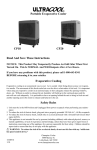
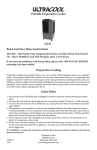
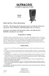
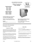
SPECIFICATIONS & SUBMITTAL DATA
FEATURES:
• Thermostat, pumps & motor included
• Automatic dump system
• Heavy gauge galvanized steel cabinet
• Electrostatically applied polyester powder coating finish
• Thermoplastic water reservoir and plastic media shield
prevent water from contacting metal cabinet
• Stainless steel pump shaft with moisture barrier
• Long life efficient media
• Removable wet section for easier installation
• Perforated prefilter screen provides greater airflow for
better cooling
• Low maintenance and trouble free
• Made in the U.S.A.
MODELS
Project
AD1C51
AS1C51
AD1C51-12
AS1C51-12
AD1C71
AS1C71
AD1C71-12
AS1C71-12
AU1C71-12
Location
Architect
Engineer
Contractor
Submitted By
Ref.
No.
1
Cooler
Model No.
Date
Qty.
CFM
Static
Pressure Motor
HP
Speed
Volts
Phase
AD2C51
AS2C51
AD2C51-12
AS2C51-12
AD2C71
AS2C71
AD2C71-12
AS2C71-12
AU2C71-12
Optional Accesories
2
3
4
5
6
7
8
9
Notes
CHAMPION COOLER
5800 Murray, Little Rock, AR 72209
1-800-643-8341
[email protected]
3-08
C
E
A
E
N
R
C
J
E
S
B
A
H
F
G
W
Y
K
E
X
D
FRONT VIEW
B
SIDE VIEW
L
TOP VIEW
CABINET DIMENSIONS*
General
Dimensions
Model No.
Opening
Water Electrical
Drain
Service
Service
Location
Location Location Location
Module
Length
Top Pan
Length
A
C
X
R
Duct
B
E
F
G
S
J
K
AD1C51
AD2C51
28
42 45 17 3/4 17 3/4 1 1/2 12 1/8
13
5 3/4 20 3/8 3 9/16 17 14 1/16 18 1/4 26 3/4 25 7/8 19 1/16
53
16
16 3/4
1
258
209
AS1C51
AS2C51
28
42 45 17 3/4 17 3/4 1 1/2 12 1/8
13
5 3/4 20 3/8 3 9/16 17 14 1/16 18 1/4 26 3/4 25 7/8 19 1/16
57
16
16 3/4
1
258
209
AD1C51-12
AD2C51-12
28
42 49 17 3/4 17 3/4 1 1/2 12 1/8
17
5 3/4 24 3/8 3 9/16 17 18 1/16 22 1/4 26 3/4 25 7/8 23 1/16
53
16
16 3/4
1
278
219
AS1C51-12
AS2C51-12
28
42 49 17 3/4 17 3/4 1 1/2 12 1/8
17
5 3/4 24 3/8 3 9/16 17 18 1/16 22 1/4 26 3/4 25 7/8 23 1/16
57
16
16 3/4
1
278
219
AD1C71
AD2C71
34 5/8 42 48 19 3/4 19 3/4 1 1/2 11 1/8
13
5 3/4 20 3/8 3 9/16 17 14 1/16 18 1/4 29 3/4 28 7/8 19 1/16
64
20
16 3/4
1
300
251
AS1C71
AS2C71
34 5/8 42 48 19 3/4 19 3/4 1 1/2 11 1/8
13
5 3/4 20 3/8 3 9/16 17 14 1/16 18 1/4 29 3/4 28 7/8 19 1/16
67
20
16 3/4
1
300
251
AD1C71-12
34 5/8 42 52 19 3/4 19 3/4 1 1/2 11 1/8
AD2C71-12
17
5 3/4 24 3/8 3 9/16 17 18 1/16 22 1/4 29 3/4 28 7/8 23 1/16
64
20
16 3/4
1
327
267
AS1C71-12
34 5/8 42 52 19 3/4 19 3/4 1 1/2 11 1/8
AS2C71-12
17
5 3/4 24 3/8 3 9/16 17 18 1/16 22 1/4 29 3/4 28 7/8 23 1/16
67
20
16 3/4
1
327
267
AU1C71-12
34 5/8 42 52 19 3/4 19 3/4 1 1/2 11 1/8
AU2C71-12
17
5 3/4 24 3/8 3 9/16 17 18 1/16 22 1/4 29 3/4 35 3/16 16 3/4
67
20
16 3/4
1
327
267
AD1C51
AS1C51
AD2C51
AS2C51
AD1C51-12
AS1C51-12
AD2C51-12
AS2C51-12
AD1C71
AS1C71
AD2C71
AS2C71
AD1C71-12
AS1C71-12
AU1C71-12
AD2C71-12
AS2C71-12
AU2C71-12
*
**
***
Speeds
Phase
Volts
Amps**
3/4
2
1
115
14.9
3/4
2
1
230
7.5
3/4
2
1
115
14.9
3/4
2
1
230
7.5
1
2
1
115
17.1
1
2
1
230
8.6
1
2
1
115
17.1
2
1
230
Dia. Width Shaft Oper. Ship.
CFM*** INCHES STATIC PRESSURE
HP
1
N
Weight
(lbs.)
W D
Models
Y
Blower Wheel
H
ELECTRICAL SPECIFICATIONS
L
Belt
Length
0"
0.1"
0.2"
0.3"
0.4"
0.5"
0.6"
3788
3630
3450
3260
3020
2806
2570
3606
3472
3317
3135
2918
2661
2379
5024
4820
4630
4450
4280
4100
3900
4941
4747
4572
4394
4208
3996
3749
8.6
All Dimensions in inches.
Blower motor (high speed) and pumps. Amp rating is Full-Load Amperage per National Electric Code.
Cubic feet per minute.